Over 50,000 hot-selling automation module components.

Fix IC695CPU310 Backplane Memory Errors | RX3i Troubleshooting

Troubleshooting IC695CPU310 Backplane Memory Read/Write Errors in PACSystems RX3i Systems

Engineers often encounter the Backplane Memory Read/Write Error in Emerson GE Fanuc PACSystems RX3i controllers. However, this diagnostic alarm does not automatically indicate a permanent hardware failure in the IC695CPU310 CPU module. Instead, it signals an error during data exchange between the central processor and the backplane. Powergear X Automation provides this technical analysis to help field engineers isolate CPU faults, rack issues, and power instability efficiently.

Understanding Backplane Communication Integrity in Factory Automation

The IC695CPU310 processor relies on the RX3i Universal Backplane to communicate with local I/O modules and power supplies. When the CPU logs a backplane memory error, it detects a failure in data transmission across the backplane bus interface. Damaged connector pins, electrical noise, or bus controller faults can cause this error. Therefore, engineers must evaluate the entire rack infrastructure before declaring the CPU defective.

Firmware and Hardware Revision Compatibility in Control Systems

Compatibility mismatches between CPU firmware and backplane hardware revisions frequently trigger false memory read/write errors. Emerson technical documentation specifies that newer IC695CHS backplanes require CPU firmware version R10.85 or higher. Swapping modules without verifying firmware compatibility leads to intermittent bus communication failures. Consequently, technicians must check part numbers and revision levels during hardware replacements.

Impact of Power Supply Stability on PLC Data Bus Performance

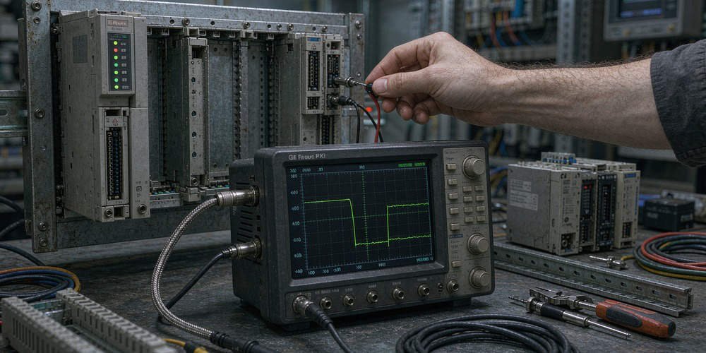
Power supply voltage fluctuations directly affect backplane bus stability in high-density automation panels. Measuring a steady 24VDC at the power supply terminals does not guarantee clean power delivery to the backplane. Transient voltage drops caused by heavy inductive motor loads can disrupt CPU bus cycles. As a result, engineers should inspect power supply fault logs and monitor millisecond-level voltage dips with oscilloscopes.

Step-by-Step Diagnostic Sequence for Fault Isolation

  1. Log Error Frequency: Record whether the fault appears constantly or occurs intermittently during machine vibration.
  2. Reseat the CPU Module: Power down the rack and inspect the multi-pin backplane connector for dust, oxidation, or bent pins.
  3. Simplify Module Configuration: Remove non-essential expansion I/O modules to isolate potential bus-loading issues.
  4. Perform Cross-Testing: Install a known-working CPU in the original rack to verify if the fault persists.

Field Installation Practices and Maintenance Guidelines

Proper physical installation prevents bus errors and extends the lifespan of industrial control hardware. Engineers must avoid hot-swapping the CPU module unless the specific RX3i system configuration permits it. Moreover, control cabinets must maintain effective equipotential bonding to reduce electromagnetic interference. According to industry reliability statistics, over 30 percent of intermittent PLC faults originate from inadequate panel grounding.

B2B Procurement Considerations for RX3i Replacement Parts

Procurement managers must verify hardware revision numbers before purchasing replacement IC695CPU310 modules. Buying refurbished components without firmware documentation increases the risk of system incompatibility. In addition, sourcing backup racks and power supplies alongside the CPU reduces downtime during emergency repairs. Working with certified automation suppliers guarantees component reliability and compatibility.

Application Scenario: Chemical Plant Compressor Control Failure

A petrochemical facility experienced intermittent IC695CPU310 backplane memory errors, causing sudden gas compressor shutdowns. The maintenance team initially suspected a failing CPU module and replaced it immediately. However, the new processor threw the exact same error within two hours of operation.

Engineers from Powergear X Automation conducted a physical inspection and discovered loose mounting screws on the RX3i backplane rack, which amplified vibration from the adjacent compressor. The mechanical movement created micro-separations at the CPU connector interface. Securing the backplane mounting rail and cleaning the gold contacts completely eliminated the communication errors without requiring further CPU replacements.

To source genuine Emerson RX3i processors, backplanes, and power supplies for your industrial facility, visit Powergear X Automation for expert technical support and hardware availability.

Frequently Asked Questions (FAQ)

Q1: Does a backplane memory read/write error mean my CPU program is corrupted?
No, this error indicates a hardware-level bus communication failure rather than logic corruption. However, severe bus errors may cause the CPU to enter Stop/Fault mode to protect process safety.

Q2: Can a faulty I/O module cause a CPU backplane memory error?
Yes, a malfunctioning I/O module can corrupt data signals on the shared backplane bus. Removing modules one by one helps identify if a specific card causes the error.

Q3: What should I do if the error disappears after cycling power?
Intermittent errors usually indicate early power supply degradation, connector oxidation, or loose rack mounting. Inspect physical connections and monitor power quality to prevent unexpected downtime.

Fix IC695CPE310 PLC & iFIX SCADA Disconnections

Troubleshooting IC695CPE310 PLC Ethernet and iFIX SCADA Disconnections

Understanding the Core Value of IC695CPE310 Controllers

The GE Fanuc PACSystems RX3i IC695CPE310 operates as a robust CPU. It features embedded Ethernet for industrial automation. Engineers rely on it for PLC logic control. It also handles PAC Machine Edition (PME) programming and SCADA data acquisition. However, field technicians often face a specific networking challenge. PME remains online, but iFIX SCADA software stops reading data. Therefore, engineers must analyze Ethernet sessions and SRTP resources. You should never replace the CPU immediately. Powergear X Automation experts recommend evaluating the iFIX driver status first.

Differentiating PME Programmer and HMI Server Connections

Many factory automation technicians misunderstand communication resource allocation. The embedded Ethernet uses the Service Request Transport Protocol (SRTP). Technical documents show the Ethernet interface supports PME via programmer connections. However, iFIX data acquisition uses separate SRTP server connections. Therefore, a working PME connection only proves the physical path exists. It does not guarantee available HMI data channels. Engineers must specifically inspect the TCP/IP link connecting the iFIX driver. Consequently, diagnosing the SCADA side prevents unnecessary hardware replacements.

Managing CPU Communication Resource Allocations

Some technicians attempt to allocate resource percentages between PME and iFIX. This configuration parameter does not actually exist. The CPE310 manages communication capability through discrete server connections. For example, LAN1 supports up to 32 SRTP server connections. It also handles Modbus/TCP server channels and Ethernet Global Data (EGD). Therefore, adding devices consumes specific protocol connections. Engineers must confirm the exact protocol iFIX utilizes. In addition, you must verify total active connections across the DCS network.

Evaluating Firmware Versions and Architecture Variations

Hardware revisions directly impact control systems capabilities. Newer CPE310-Bxxx hardware features a different processing architecture. This upgrade improves overall Ethernet communication performance. Therefore, field engineers must record exact CPU part numbers. You must also document the primary firmware version. Furthermore, verify compatibility with your PAC Machine Edition version. Do not assume all CPE310 modules share identical capabilities. Proper version matching ensures stable factory automation networks.

Executing Read-Only Diagnostics Before Parameter Changes

We advise against modifying CPU Ethernet parameters immediately. If PME connects successfully, basic Ethernet hardware works correctly. Therefore, changing IP addresses or subnet masks can disrupt programming access. You should perform read-only diagnostics instead. Check the CPU status and controller fault tables first. Evaluate Ethernet communication diagnostics for error flags. Moreover, identify the exact iFIX server IP address. Finally, verify the active TCP connection status from the Windows command line.

Clearing Ghost TCP Sessions in Industrial Networks

Factory SCADA systems often deploy multiple servers and historian nodes. Power outages or switch reboots can create ghost connections. Consequently, old TCP sessions might not release immediately. A timeout mechanism exists for PME programmer connections. However, this does not apply to SRTP application channels. Therefore, multiple inactive sessions can exhaust the 32 available server connections. Engineers should use network diagnostic tools to locate abandoned sessions. Releasing these sessions often restores iFIX communication instantly.

Optimizing SCADA Polling Configurations for Reliability

Excessive data requests easily overwhelm PLC communication buffers. Many facilities configure iFIX to poll large tag volumes rapidly. Consequently, aggressive scan times generate massive Ethernet traffic. We recommend optimizing data block sizes to reduce overhead. Engineers should eliminate duplicate tag read requests across multiple nodes. Therefore, improving polling efficiency resolves most resource exhaustion problems. Do not arbitrarily increase communication timeout parameters. Proper configuration ensures long-term stability in control systems.

Application Scenario: Restoring Process Control Communications

A chemical plant lost iFIX SCADA visibility recently. However, their engineering station maintained PME programming access perfectly. The maintenance team planned an emergency CPU replacement. Powergear X Automation intervened and analyzed the network traffic. We discovered a redundant alarm server holding 25 inactive SRTP sessions. We executed the following technical steps:

  • Step 1: Verified CPU hardware status via PME.
  • ⚙️ Step 2: Checked the active TCP sessions using Windows command line.
  • 🔧 Step 3: Restarted the polling service to clear ghost connections.

As a result, data acquisition resumed without replacing any hardware. To explore reliable hardware solutions and technical support, visit Powergear X Automation to enhance your industrial infrastructure today.

Frequently Asked Questions (FAQ)

Q1: Can the IC695CPE310 connect to PME and iFIX simultaneously?
Yes, it supports simultaneous connections. However, you must monitor total active SRTP server connections. The CPU limits these connections based on firmware versions.

Q2: Should I change the Advanced User Parameters (AUP) if iFIX drops?
No, you should avoid modifying AUP initially. Verify active TCP sessions and optimize SCADA polling rates first. Unnecessary AUP changes cause further network instability.

Q3: Why does PME stay online while iFIX loses connection?
PME uses dedicated programmer connections. Meanwhile, iFIX consumes separate server connection resources. Ghost TCP sessions easily exhaust server connections while leaving programmer connections available.

Fix PACSystems RX3i IC695CRU320 Dual CPU Failover & Sync Issues

Troubleshooting PACSystems RX3i IC695CRU320 Dual Redundancy CPU Failover Issues

In high-availability industrial automation environments, continuous runtime remains non-negotiable. Dual-redundant Programmable Logic Controller (PLC) configurations protect continuous process facilities from unplanned downtime. The Emerson GE Fanuc PACSystems RX3i IC695CRU320 CPU delivers high-speed CPU redundancy across critical process applications. However, plant engineers sometimes report that a secondary CPU fails to take control when the primary CPU faults, even with dual optical fiber links intact. Powergear X Automation provides this troubleshooting guide to resolve failover delays and synchronization errors in IC695CRU320 systems.

Physical Fiber Integrity Does Not Equal CPU Synchronization

A common misconception in factory automation involves confusing physical link status with application synchronization. The IC695CRU320 CPU relies on IC695RMX128 or IC695RMX228 Redundancy Memory Xchange modules to mirror controller memory. Dual fiber optic lines provide link redundancy, but healthy fiber optical LEDs only confirm physical layer continuity. If the backup CPU encounters hardware mismatches or fatal faults, it refuses to enter the Synchronized Backup state. Consequently, the primary CPU failure triggers an unrecoverable system shutdown instead of a seamless failover.

Understanding the Fail Wait Time Parameter in Redundant Systems

PACSystems RX3i hot standby architectures utilize discrete synchronization points within each scan cycle. The default Fail Wait Time setting operates at 60 milliseconds, adjustable from 40 to 400 milliseconds. If the active CPU fails to reach a synchronization checkpoint within this window, the secondary unit initiates takeover protocols. However, the backup CPU must maintain full synchronization prior to the event. According to industrial automation reliability reports, over 70% of redundant failover errors stem from pre-existing synchronization loss rather than physical link disruption.

Hardware Revision and Firmware Compatibility Requirements

Deploying a high-availability DCS or PLC architecture requires identical CPU and hardware revisions. Primary and secondary RX3i racks must run identical firmware versions and match memory configurations. For example, mixing an older IC695CRU320 CPU revision with a newer hardware module causes parameter rejection during runtime synchronization. Furthermore, engineers must verify that both controllers reside on compatible RX3i Universal Backplanes (IC695CHS012 or IC695CHS016) rather than legacy Series 90-30 expansion racks.

Step-by-Step Diagnostic Sequence for Secondary CPU Failover

  1. Inspect the Redundancy Fault Table: Connect via Proficy Machine Edition (PME) and examine Controller Fault Group 138 to identify specific synchronization errors.
  2. Verify RMX Module Diagnostics: Check the OK, OWN, DATA, and SIGNAL DETECT LEDs on both IC695RMX128 modules to confirm internal memory transfers.
  3. Validate Synchronized Status: Confirm that the PME software status bar explicitly reports “Synchronized Backup” for the secondary controller.
  4. Audit PME Project Hardware Configuration: Verify that the Transfer List, Redundancy Mode, and Primary/Secondary settings match across both CPU projects.

Proactive Maintenance Practices for Industrial Control Systems

Preventive maintenance minimizes unexpected failover disruptions in continuous process plants. Maintenance teams should routinely archive CPU diagnostic logs and back up active PME projects. When replacing a damaged IC695CRU320 module, engineers should verify firmware parity before inserting the card into a live backplane. Additionally, system integrators must schedule periodic failover tests during planned maintenance windows to validate seamless takeover under load.

B2B Sourcing and Legacy Replacement Strategies

Procuring replacement parts for legacy GE Fanuc or modern Emerson PACSystems RX3i platforms requires thorough verification. B2B buyers should avoid sourcing replacement CPUs based solely on the core part number. Requesting firmware documentation, hardware revision levels, and battery test records ensures immediate drop-in compatibility. Purchasing verified hardware prevents configuration mismatches and protects critical automation infrastructure from extended downtime.

Application Scenario: Petrochemical Distillation Unit Recovery

A continuous chemical refinery experienced an unprogrammed plant shutdown when the primary IC695CRU320 CPU suffered a power supply trip. Although dual fiber cables connected the RMX228 modules, the backup CPU failed to assume control. The engineering team connected PME software and discovered Fault Group 138 error codes indicating an unsynchronized memory transfer list. A previous maintenance update modified the primary CPU variable transfer list without updating the secondary project file.

The team re-aligned the PME project configurations, re-downloaded the matching hardware settings, and re-established the “Synchronized Backup” state across both racks. During a subsequent planned simulation, disconnecting the primary CPU power triggered an immediate, bumpless transfer to the backup unit within 30 milliseconds, maintaining uninterrupted valve control across the refinery process.

To optimize your control system uptime with genuine PLC components and expert technical support, visit Powergear X Automation to explore our inventory of PACSystems RX3i solutions.

Frequently Asked Questions (FAQ)

Q1: Why does the secondary IC695CRU320 CPU show RUN mode but fail to take over during an active CPU fault?
RUN mode only indicates that the CPU is executing logic. The secondary unit must explicitly reach the “Synchronized Backup” state to take control; otherwise, it lacks the real-time process data necessary to manage outputs safely.

Q2: Can I pair an IC695CRU320 CPU with a different RX3i CPU model like the CPE330?
No. Hot standby redundancy requires identical or strictly qualified compatible CPU architectures. Mixing different CPU families prevents memory synchronization and breaks redundancy logic.

Q3: What indicates that an IC695RMX128 redundancy module requires replacement?
If the RMX module OK LED remains unlit or indicates an internal hardware failure after a rack power cycle, the module cannot exchange memory data and must be replaced to restore redundancy.

RX3i IC695CPU320 Expansion Rack Latency Explained

Why PACSystems RX3i IC695CPU320 Shows Higher I/O Latency on Expansion Racks

Engineers managing modern industrial automation systems often notice delayed I/O response on expansion racks. The GE Fanuc PACSystems RX3i IC695CPU320 delivers high processing speed in factory automation. However, placing modules in expansion chassis introduces measurable network transport delays. Powergear X Automation presents this analysis to explain why expansion racks experience higher scan latency and how to optimize chassis layouts.

The Architectural Value of RX3i Expansion Racks

The IC695CPU320 central processor manages system execution, memory allocation, and backplane control systems scanning. System designers utilize expansion racks to lower field wiring costs across distributed industrial plants. In water treatment facilities or oil refineries, expansion cabinets sit near remote process equipment. While expansion chassis simplify physical installation, data must travel through additional interface modules. Therefore, system integrators must account for communication overhead when placing time-critical control loops.

Extended Data Paths Increase Backplane Scan Delays

The main rack processor accesses local input and output channels directly through the primary RX3i backplane bus. Conversely, expansion racks require multiple data conversion hops across expansion transmitter and receiver modules. Data must flow across the CPU, local backplane, expansion interface, interconnecting cable, and remote backplane. As a result, input signals require several extra milliseconds to register within the PLC scan cycle. High-speed interlocks and motion control triggers must remain on the primary chassis.

Impact of Rack Quantities on Total Scan Cycles

Expanding the physical I/O count increases the workload on the PACSystems CPU communication tasks. According to industrial Ethernet reports, bus cycle times rise linearly as node counts increase. Adding multiple expansion racks with heavy analog density lengthens overall logic execution times. Engineers frequently mistake communication latency for insufficient CPU processing power. Moreover, overloading expansion buses causes variable jitter in closed-loop PID control routines.

Comparative Response Characteristics Across I/O Types

Different module architectures show varying levels of sensitivity to expansion rack latency during real-time operation:

  • Digital Input Modules: Digital points process rapidly, yet fast proximity switches experience delayed edge detection on remote buses.
  • Analog Input Modules: Analog hardware requires onboard A/D conversion and digital filtering before transmitting data. Placing analog units on expansion racks adds network latency to the conversion time.
  • High-Speed Counters: Pulse counting modules lose precise timestamp synchronization when separated from the primary CPU backplane bus.

Optimizing Chassis Layouts for Factory Automation

Automation engineers must structure control cabinets based on signal response priorities to maintain deterministic control performance:

  • Primary Main Rack Placement: Assign emergency shut-off inputs, high-speed counters, servo triggers, and safety interlocks to the local chassis.
  • Expansion Chassis Placement: Position ambient temperature monitoring, slow tank level sensors, and general status indicators on remote expansion racks.
  • Network Cable Isolation: Route expansion bus cables away from high-voltage motor wires to prevent packet retransmissions and dropped frames.

Step-by-Step Optimization Sequence for System Integrators

  1. Audit CPU Scan Timing: Utilize Proficy Machine Edition software tools to analyze actual logic scan times and backplane sweep durations.
  2. Reassign Critical Channels: Move fast safety loops and precision positioning modules from expansion racks to the primary chassis.
  3. Verify Cable Shielding: Ensure expansion bus cables maintain solid single-point grounding to eliminate electromagnetic noise interference.
  4. Benchmark Control Performance: Measure the total loop response time before and after adjusting module locations to confirm performance gains.

Field Installation Standards and EMC Guidelines

Proper physical wiring provides essential protection against data corruptions on extended expansion bus lines. Installation teams must follow international electrical standards including IEC 61000 and IEC 60204-1 safety guidelines. Expansion cables running near large variable frequency drives suffer from high common-mode noise. Engineers must run communication lines inside grounded metallic conduits and maintain strict perpendicular crossings against power cables.

B2B Procurement and CPU Compatibility Considerations

Procurement teams sourcing replacement CPU modules or expansion chassis must verify hardware revision compatibility carefully. Replacing an older GE Fanuc IC695CPU320 with a modern Emerson equivalent requires checking backplane firmware levels and PME project versions. Deploying mismatching hardware catalogs can cause backplane communication faults or channel configuration errors. System integrators should test hardware configurations offline before scheduling plant shutdowns.

Application Scenario: Petrochemical Pumping Facility

A petrochemical processing plant experienced erratic pressure trips on a main feed pump. Engineers originally installed the high-speed pressure transmitter module on a third expansion chassis located 50 meters away. Communication bus latency caused a 15-millisecond delay during pressure spike events, triggering false emergency shutdowns.

The site team resolved the issue by relocating the pressure input module to the primary CPU rack. In addition, they assigned general temperature monitoring channels to the expansion rack. This structural change reduced the pressure loop latency to under two milliseconds, eliminating false trips while maintaining remote monitoring capability across the plant.

For high-quality hardware components and expert technical assistance with PACSystems RX3i architectures, visit Powergear X Automation to upgrade your industrial infrastructure today.

Frequently Asked Questions (FAQ)

Q1: Will upgrading to a faster CPU eliminate expansion rack I/O latency?
No. Upgrading the CPU speeds up logic execution, but network transport delays across the expansion bus remain unchanged. Reorganizing module positions yields better latency reduction.

Q2: Can I use expansion racks for emergency shutdown (ESD) signals?
Industry best practices recommend placing critical safety interlocks on the primary rack to ensure minimum delay and deterministic response during trip events.

Q3: How do I identify expansion bus communication errors in Proficy Machine Edition?
Open the PME Controller Diagnostic Window and examine the fault table for loss of module errors or backplane parity warnings.

Fix IC695CNM001 ControlNet NUT Error | Network Troubleshooting

Resolving Network Update Time (NUT) Errors on PACSystems RX3i IC695CNM001 Modules

In GE Fanuc PACSystems RX3i architectures, the IC695CNM001 ControlNet module acts as a critical communication bridge between central processors and distributed I/O nodes. When systems trigger a Network Update Time (NUT) error, engineers often suspect internal hardware failure. However, real-world field experience indicates that network scheduling conflicts, bandwidth saturation, or cabling defects cause most NUT faults. Powergear X Automation presents this diagnostic guide to help control system engineers identify root causes and systematically restore ControlNet communication stability.

Understanding the Role of Network Update Time in ControlNet Systems

ControlNet relies on a deterministic communication model to ensure precise real-time control. Network Update Time (NUT) defines the exact cycle duration required for all nodes to transfer scheduled data. Modern industrial automation platforms mandate predictable data updates for critical loops. According to ARC Advisory Group research, deterministic industrial communication prevents costly unscheduled downtime in continuous process operations. The IC695CNM001 module executes scheduled data transfers within this fixed NUT window, ensuring reliable timing across discrete and process automation environments.

Root Causes of Scheduled Bandwidth Saturation and NUT Failures

Adding new remote I/O drops or field transmitters without recalculating network parameters frequently causes NUT errors. New nodes consume additional scheduled bandwidth within the ControlNet network schedule. As a result, the total transmission time exceeds the configured NUT limit. Moreover, electromagnetic interference from nearby variable frequency drives can corrupt data frames, forcing retransmissions that disrupt deterministic timing. Engineers must review scheduled bandwidth utilization in the ControlNet configuration tool and expand the NUT parameter when expanding network nodes.

Addressing ControlNet Protocol Compatibility and Keeper Node Errors

System upgrades and spare part replacements introduce hidden configuration risks. Physical hardware replacement alone does not guarantee automatic network recovery. ControlNet networks rely on dedicated Keeper nodes to store and distribute active network schedules. Replacing an IC695CNM001 module without verifying its firmware compatibility against the Proficy Machine Edition (PME) project can lock out communication. Furthermore, mismatched MAC ID addresses or missing Keeper configuration files prevent new modules from synchronizing with active nodes on the bus.

Evaluating Physical Layer Integrity and Signal Attenuation Factors

Physical cable degradation remains a major cause of intermittent ControlNet network collapse. ControlNet uses high-frequency RG-6 75-ohm coaxial cabling with specialized BNC taps. Loose connections caused by machinery vibration gradually increase signal attenuation. Furthermore, poor control cabinet grounding creates ground loops that introduce high-frequency noise onto the signal line. Field technicians must regularly inspect end-of-line terminating resistors, loose BNC fittings, and cable bend radiuses to maintain strict physical layer standards.

Step-by-Step Diagnostic Sequence for Network Recovery

  1. Check Physical Connections: Inspect all BNC connectors, T-taps, and terminating resistors across the ControlNet segment for mechanical damage or oxidation.
  2. Verify MAC ID and Keeper Status: Confirm that the replacement module matches the target node address and holds valid Keeper schedule information.
  3. Analyze Bandwidth in PME: Open Proficy Machine Edition and run the ControlNet configuration utility to evaluate total scheduled bandwidth usage.
  4. Adjust NUT Parameters: Incrementally increase the Network Update Time constant or optimize I/O mapping if scheduled bandwidth exceeds recommended limits.

Best Practices for Module Replacement and Procurement

When procuring replacement IC695CNM001 modules for legacy GE Fanuc or current Emerson RX3i systems, procurement managers must check revision histories. Verify the hardware catalog number, firmware revision, and CPU compatibility prior to installation. Always upload and backup active ControlNet schedule files before removing old hardware. Storing offline configuration backups significantly reduces system recovery time during unexpected field breakdowns.

Application Scenario: Petrochemical Distillation Column Upgrade

During a system expansion at a chemical processing facility, field engineers added three remote I/O racks to an active ControlNet trunk. Shortly after commissioning, the primary IC695CNM001 module reported persistent NUT errors, causing remote I/O drops to go offline and tripping the column pressure control loop.

The engineering team initially suspected module failure and swapped the hardware, but the error persisted. Upon reviewing the network properties in the ControlNet Configuration Tool, they discovered that scheduled bandwidth utilization had reached 98%. The added I/O modules pushed data cycle times beyond the original 5ms NUT setting.

To resolve the fault, the team adjusted the NUT parameter from 5ms to 10ms and optimized the RPI (Requested Packet Interval) settings on non-critical temperature channels. This reduced scheduled bandwidth utilization to 68%, restoring network stability and preventing control loop lockups without requiring physical network rewiring.

For high-quality industrial components and professional replacement modules, visit Powergear X Automation to explore reliable solutions for your automation systems.

Frequently Asked Questions (FAQ)

Q1: Does a NUT Error mean the IC695CNM001 module hardware is defective?
No. A NUT error indicates that the network cannot complete its scheduled data cycle within the configured time. Unintended bandwidth overload, incorrect node addresses, or cable damage usually cause this issue rather than hardware failure.

Q2: Can I swap an IC695CNM001 module without downloading new configuration files?
No. ControlNet modules require correct node MAC ID assignments and network schedule files from the Keeper node. Replacing a module requires downloading the saved ControlNet network configuration via Proficy Machine Edition.

Q3: What is the recommended maximum scheduled bandwidth for ControlNet networks?
Engineers should keep scheduled bandwidth utilization below 80%. Running networks near 100% capacity leaves no headroom for transient noise recovery, leading to frequent NUT timing faults.

Fix 50Hz Noise on PACSystems RX3i IC695ALG508 Analog Modules

Why PACSystems RX3i IC695ALG508 Suffers from 50Hz Interference and How to Optimize Digital Filtering

In modern industrial automation, precision data acquisition forms the backbone of reliable distributed control systems (DCS) and programmable logic controllers (PLC). However, field engineers frequently encounter periodic fluctuations in analog channels, particularly when operating near variable frequency drives (VFDs) or high-power motors. The Emerson PACSystems RX3i IC695ALG508 isolated analog input module is highly capable, yet it remains susceptible to 50Hz power line electromagnetic interference (EMI). Powergear X Automation presents this technical analysis to explain the root causes of this sensitivity and provide actionable steps to configure digital filtering parameters effectively.

The Architecture of Isolated Inputs in Factory Automation

The IC695ALG508 module utilizes a channel-to-channel isolated input structure to mitigate electrical noise. Traditional non-isolated modules share a common ground, which frequently introduces ground loops when field devices sit hundreds of meters away from the control cabinet. Signal cables running through crowded cable trays encounter transient electromagnetic fields from adjacent power lines. While the isolated architecture of this module prevents ground potential differences from disrupting adjacent channels, it cannot completely eliminate localized differential noise. B2B engineers must recognize that hardware isolation serves as a defense mechanism, not a substitute for proper cable segregation.

Balancing Analog Conversion Speed and Signal Stability

Optimizing factory automation systems requires balancing raw analog-to-digital (A/D) conversion speed against digital filter lag. Industrial processes present conflicting requirements for response times. For instance, boiler pressure control loops can tolerate higher filtering coefficients because pressure changes occur relatively slowly. Conversely, fast flow control loops or safety interlock systems require low latency. Implementing excessive filtering delays critical alarm triggers and destabilizes proportional-integral-derivative (PID) loop calculations. Therefore, system integrators must align the module hardware configuration with the specific dynamic characteristics of the process.

Root Causes of Module Sensitivity to 50Hz Noise

Three primary factors contribute to 50Hz power frequency interference sensitivity in precision analog modules:

  • Low-Amplitude Signal Profiles: Standard 4-20mA loops operate with a narrow 16mA active span. Micro-ampere level induced currents from surrounding machinery introduce noticeable measurement errors.
  • Inductive Antennas via Long Cable Runs: Parallel routing of signal lines alongside heavy-duty motor cables creates electromagnetic coupling, which manifests as a distinct 50Hz oscillation on the PLC registers.
  • Common-Mode Noise from Ground Loops: Large-scale manufacturing plants often exhibit minor voltage variations between separate structural ground points, which injects unwanted voltage offsets into the reading.

Configuring Digital Filtering Parameters in PME Software

Engineers configure the digital filtering coefficients for the IC695ALG508 within the Proficy Machine Edition (PME) hardware configuration interface. Increasing the filter value dampens periodic noise but increases the signal settling time. The following guidelines assist in choosing the correct filter values based on typical process dynamics:

  • Temperature and Level Monitoring: Apply high filtering coefficients. These processes change slowly and benefit most from smooth data trends.
  • Standard Pressure and Flow Loops: Apply medium filtering coefficients to balance noise rejection with control loop responsiveness.
  • High-Speed Closed-Loop Control: Minimize filtering to maintain real-time tracking, relying instead on physical shielding to block EMI.
  • VFD-Adjacent Inlets: Target specific power frequency rejection settings (such as selecting the 50Hz notch filter option in the hardware configuration) to suppress cyclic drive noise.

Step-by-Step Commissioning Sequence for Noise Suppression

  1. Analyze the Noise Profile: Utilize an oscilloscope or the PME trend monitoring tool to verify if the signal fluctuation matches the 50Hz grid frequency or syncs with motor start cycles.
  2. Adjust the Notch Filter: Select the hardware-based 50Hz line filter frequency option inside the module configuration properties to activate the internal digital notch filter.
  3. Incrementally Adjust Digital Filtering: Raise the software input filter time constant step-by-step while observing the process variable smoothness.
  4. Validate PID Stability: Verify that the added filter delay does not cause the control loop output to oscillate or overshoot its setpoint.

Field Installation Practices and Compliance Standards

Robust physical installation provides the foundation for digital filtering success. Industrial wiring designs must adhere to international EMC standards such as IEC 61000 and electrical safety regulations under IEC 60204-1. Signal cables must run in dedicated grounded metallic conduits, crossing high-voltage power lines strictly at 90-degree angles to minimize inductive coupling. Furthermore, engineers must connect shielded twisted-pair cable shields to ground at the control cabinet side only. Dual-ended grounding introduces circulating ground loop currents, which increases the noise the digital filter must handle.

B2B Procurement and Compatibility Assessment

When procuring or replacing IC695ALG508 modules for legacy GE Fanuc or modern Emerson RX3i installations, system compatibility requires careful review. The integration team must verify the existing RX3i CPU firmware version and the PME software edition. While modern Emerson modules maintain physical backward compatibility with older IC695 backplanes, deploying them without updating the PLC configuration files can cause channel parameter mismatches or missing diagnostic alarms. Procurement managers should perform offline configuration validation before scheduling maintenance downtime.

Application Scenario: VFD-Driven Pumping Station

In a recent municipal water distribution project, a flow transmitter located near a 110kW variable frequency drive experienced severe value fluctuations, varying by up to 8% of the total scale. The engineering team initially maximized the software digital filter, which stabilized the reading but caused the PID control valve to hunt continuously due to a two-second signal lag.

To resolve the issue, the team implemented a dual-layer approach. First, they rerouted the 4-20mA signal cable into a separate conduit away from the VFD output lines. Second, they adjusted the IC695ALG508 module configuration by setting the line filter frequency specifically to 50Hz and reducing the software filter time constant to a moderate value. This combination restored signal stability within 0.5% of the scale while maintaining a rapid 100-millisecond response time, ensuring stable pressure regulation without valve hunting.

For reliable hardware sourcing and expert technical support on PACSystems RX3i components, visit Powergear X Automation to find high-performance modules for your industrial infrastructure.

Frequently Asked Questions (FAQ)

Q1: Can I use software filtering to fix bad analog cable shielding?
No. Software filtering dampens minor periodic fluctuations but cannot correct severe signal distortion, clipping, or intermittent spikes caused by poor shielding. Rectifying physical EMC issues must always precede software parameter adjustments.

Q2: What is the difference between the module’s line filter frequency and the digital filter time constant?
The line filter frequency sets an internal hardware notch filter (typically at 50Hz or 60Hz) designed to block grid-induced power frequency noise. The digital filter time constant applies a running average or low-pass calculation to smooth out general process variations over time.

Q3: Why does my PLC configuration reject the IC695ALG508 module during download?
This issue usually stems from a mismatch between the hardware catalog version selected in your PME project and the physical firmware version of the module. Ensure your PME software device catalog is updated to match the exact hardware revision.

Maximizing Uptime: Why GE RX3i Excels in Continuous Production

RX7i to RX3i Migration Guide | Optimize Industrial Control

Maximizing Industrial Efficiency: Migrating from RX7i to PACSystems RX3i

The Strategic Value of System Modernization

Modernizing your control infrastructure from the legacy RX7i to the PACSystems RX3i platform represents a significant leap in operational capability. In my experience at Powergear X Automation, we see that this transition isn’t just about replacing hardware. It is about unlocking higher communication bandwidth and superior flexibility. Industries such as petrochemicals and pharmaceuticals require precise control. Consequently, the RX3i provides the necessary backbone for complex logic and high-speed data acquisition.

Maximizing Uptime: Why GE RX3i Excels in Continuous Production

Technical Deep Dive: Processing Power and Memory

The heart of the RX3i upgrade lies in its advanced CPU modules, such as the IC698CPE020, CPE030, and CPE040. These processors utilize Pentium M technology to deliver significantly faster clock speeds compared to their predecessors.

  • Reduced Cycle Times: Higher clock speeds shorten logic scan cycles.
  • Precision Control: Faster response improves temperature regulation in chemical reactors.
  • Waste Reduction: High-speed packaging lines benefit from decreased reject rates.

Moreover, the expanded cache memory ensures that the system handles large-scale automation tasks without latency.

Ensuring Continuity through Advanced Redundancy

For mission-critical environments, the IC698CRE020 redundancy module is indispensable. This hardware facilitates instantaneous synchronized switching between primary and backup controllers.

  • Zero Downtime: Automated failover prevents costly unplanned shutdowns.
  • Safety Compliance: The architecture aligns with rigorous IEC 61508 standards.
  • Risk Mitigation: Redundancy eliminates single points of failure in energy grids.

Our team often notes that high-reliability systems pay for themselves by avoiding just one hour of production stoppage.

Optimizing Connectivity and Protocol Integration

The IC698ETM001 Ethernet module serves as the bridge for modern industrial internet of things (IIoT) applications. It supports 100 Mbps throughput and integrates seamlessly with Modbus/TCP and GE Ethernet/IP protocols. Therefore, users experience significantly lower latency in SCADA systems. This improved connectivity allows for smoother remote diagnostics. As a result, engineers spend less time on-site during commissioning and troubleshooting phases.

Best Practices for Installation and Maintenance

To ensure long-term stability, technical teams must follow strict physical installation protocols. High-vibration environments demand specific mechanical reinforcements.

  • Use anti-vibration bolts to secure CPU modules.
  • Apply vibration-resistant ferrules on all wiring ports.
  • Install external surge protectors for Ethernet interfaces.
  • Maintain cabinet temperatures between 0°C and 60°C.
  • Clean air ducts and cooling fans quarterly.

Proper thermal management prevents premature component aging. Furthermore, shielding the CPU from power surges protects your capital investment from grid fluctuations.

Powergear X Automation Commentary

At Powergear X Automation, we believe the industry is shifting toward “Software-Defined Automation.” While the RX3i is robust hardware, its true strength lies in how it handles data-intensive workloads. We recommend that users do not just “swap” modules. Instead, use this migration to audit your network topology. Upgrading to RX3i offers a rare window to optimize your entire control loop for the next decade of production.

Practical Application Scenarios

  • Petrochemical Refining: Managing thousands of I/O points with high-speed redundancy for safety-instrumented functions.
  • Pharmaceutical Batching: Utilizing precise CPU scanning to meet strict FDA regulatory tracking and dosage accuracy.
  • Automotive Assembly: Integrating multiple third-party sensors via Ethernet/IP for real-time quality monitoring.

Frequently Asked Questions (FAQ)

1. When is the right time to move from RX7i to RX3i?
You should consider an upgrade if your current RX7i system experiences “logic lag” or if you cannot find spare parts easily. Additionally, if your facility requires better integration with modern SCADA or Cloud platforms, the RX3i is the logical successor.

2. Can I reuse my existing RX7i I/O racks with a new RX3i CPU?
The RX3i is designed for high backward compatibility. Most RX7i I/O modules work perfectly; however, very early ETM modules or specialized high-power units may require firmware updates. We suggest a full compatibility audit before purchasing.

3. What is the most common mistake during RX3i commissioning?
The most frequent error is neglecting the grounding and surge protection of the Ethernet ports. Unlike older serial connections, high-speed Ethernet is sensitive to electromagnetic interference. Always use industrial-grade shielded cables to ensure data integrity.

Looking for genuine GE PACSystems components or expert migration support? Visit the experts at Powergear X Automation to find the latest CPU modules and customized control solutions for your facility.

PACSystems RX3i IO

PACSystems RX3i I/O: A Comprehensive Guide

Discover the power of PACSystems™ RX3i I/O modules. Learn about their key features, functionalities, and applications in industrial automation. This comprehensive guide explores how RX3i I/O modules can enhance efficiency, reliability, and flexibility in your control systems.

Back to Top
Product has been added to your cart