Over 50,000 hot-selling automation module components.

Fix 50Hz Noise on PACSystems RX3i IC695ALG508 Analog Modules

Why PACSystems RX3i IC695ALG508 Suffers from 50Hz Interference and How to Optimize Digital Filtering

In modern industrial automation, precision data acquisition forms the backbone of reliable distributed control systems (DCS) and programmable logic controllers (PLC). However, field engineers frequently encounter periodic fluctuations in analog channels, particularly when operating near variable frequency drives (VFDs) or high-power motors. The Emerson PACSystems RX3i IC695ALG508 isolated analog input module is highly capable, yet it remains susceptible to 50Hz power line electromagnetic interference (EMI). Powergear X Automation presents this technical analysis to explain the root causes of this sensitivity and provide actionable steps to configure digital filtering parameters effectively.

The Architecture of Isolated Inputs in Factory Automation

The IC695ALG508 module utilizes a channel-to-channel isolated input structure to mitigate electrical noise. Traditional non-isolated modules share a common ground, which frequently introduces ground loops when field devices sit hundreds of meters away from the control cabinet. Signal cables running through crowded cable trays encounter transient electromagnetic fields from adjacent power lines. While the isolated architecture of this module prevents ground potential differences from disrupting adjacent channels, it cannot completely eliminate localized differential noise. B2B engineers must recognize that hardware isolation serves as a defense mechanism, not a substitute for proper cable segregation.

Balancing Analog Conversion Speed and Signal Stability

Optimizing factory automation systems requires balancing raw analog-to-digital (A/D) conversion speed against digital filter lag. Industrial processes present conflicting requirements for response times. For instance, boiler pressure control loops can tolerate higher filtering coefficients because pressure changes occur relatively slowly. Conversely, fast flow control loops or safety interlock systems require low latency. Implementing excessive filtering delays critical alarm triggers and destabilizes proportional-integral-derivative (PID) loop calculations. Therefore, system integrators must align the module hardware configuration with the specific dynamic characteristics of the process.

Root Causes of Module Sensitivity to 50Hz Noise

Three primary factors contribute to 50Hz power frequency interference sensitivity in precision analog modules:

  • Low-Amplitude Signal Profiles: Standard 4-20mA loops operate with a narrow 16mA active span. Micro-ampere level induced currents from surrounding machinery introduce noticeable measurement errors.
  • Inductive Antennas via Long Cable Runs: Parallel routing of signal lines alongside heavy-duty motor cables creates electromagnetic coupling, which manifests as a distinct 50Hz oscillation on the PLC registers.
  • Common-Mode Noise from Ground Loops: Large-scale manufacturing plants often exhibit minor voltage variations between separate structural ground points, which injects unwanted voltage offsets into the reading.

Configuring Digital Filtering Parameters in PME Software

Engineers configure the digital filtering coefficients for the IC695ALG508 within the Proficy Machine Edition (PME) hardware configuration interface. Increasing the filter value dampens periodic noise but increases the signal settling time. The following guidelines assist in choosing the correct filter values based on typical process dynamics:

  • Temperature and Level Monitoring: Apply high filtering coefficients. These processes change slowly and benefit most from smooth data trends.
  • Standard Pressure and Flow Loops: Apply medium filtering coefficients to balance noise rejection with control loop responsiveness.
  • High-Speed Closed-Loop Control: Minimize filtering to maintain real-time tracking, relying instead on physical shielding to block EMI.
  • VFD-Adjacent Inlets: Target specific power frequency rejection settings (such as selecting the 50Hz notch filter option in the hardware configuration) to suppress cyclic drive noise.

Step-by-Step Commissioning Sequence for Noise Suppression

  1. Analyze the Noise Profile: Utilize an oscilloscope or the PME trend monitoring tool to verify if the signal fluctuation matches the 50Hz grid frequency or syncs with motor start cycles.
  2. Adjust the Notch Filter: Select the hardware-based 50Hz line filter frequency option inside the module configuration properties to activate the internal digital notch filter.
  3. Incrementally Adjust Digital Filtering: Raise the software input filter time constant step-by-step while observing the process variable smoothness.
  4. Validate PID Stability: Verify that the added filter delay does not cause the control loop output to oscillate or overshoot its setpoint.

Field Installation Practices and Compliance Standards

Robust physical installation provides the foundation for digital filtering success. Industrial wiring designs must adhere to international EMC standards such as IEC 61000 and electrical safety regulations under IEC 60204-1. Signal cables must run in dedicated grounded metallic conduits, crossing high-voltage power lines strictly at 90-degree angles to minimize inductive coupling. Furthermore, engineers must connect shielded twisted-pair cable shields to ground at the control cabinet side only. Dual-ended grounding introduces circulating ground loop currents, which increases the noise the digital filter must handle.

B2B Procurement and Compatibility Assessment

When procuring or replacing IC695ALG508 modules for legacy GE Fanuc or modern Emerson RX3i installations, system compatibility requires careful review. The integration team must verify the existing RX3i CPU firmware version and the PME software edition. While modern Emerson modules maintain physical backward compatibility with older IC695 backplanes, deploying them without updating the PLC configuration files can cause channel parameter mismatches or missing diagnostic alarms. Procurement managers should perform offline configuration validation before scheduling maintenance downtime.

Application Scenario: VFD-Driven Pumping Station

In a recent municipal water distribution project, a flow transmitter located near a 110kW variable frequency drive experienced severe value fluctuations, varying by up to 8% of the total scale. The engineering team initially maximized the software digital filter, which stabilized the reading but caused the PID control valve to hunt continuously due to a two-second signal lag.

To resolve the issue, the team implemented a dual-layer approach. First, they rerouted the 4-20mA signal cable into a separate conduit away from the VFD output lines. Second, they adjusted the IC695ALG508 module configuration by setting the line filter frequency specifically to 50Hz and reducing the software filter time constant to a moderate value. This combination restored signal stability within 0.5% of the scale while maintaining a rapid 100-millisecond response time, ensuring stable pressure regulation without valve hunting.

For reliable hardware sourcing and expert technical support on PACSystems RX3i components, visit Powergear X Automation to find high-performance modules for your industrial infrastructure.

Frequently Asked Questions (FAQ)

Q1: Can I use software filtering to fix bad analog cable shielding?
No. Software filtering dampens minor periodic fluctuations but cannot correct severe signal distortion, clipping, or intermittent spikes caused by poor shielding. Rectifying physical EMC issues must always precede software parameter adjustments.

Q2: What is the difference between the module’s line filter frequency and the digital filter time constant?
The line filter frequency sets an internal hardware notch filter (typically at 50Hz or 60Hz) designed to block grid-induced power frequency noise. The digital filter time constant applies a running average or low-pass calculation to smooth out general process variations over time.

Q3: Why does my PLC configuration reject the IC695ALG508 module during download?
This issue usually stems from a mismatch between the hardware catalog version selected in your PME project and the physical firmware version of the module. Ensure your PME software device catalog is updated to match the exact hardware revision.

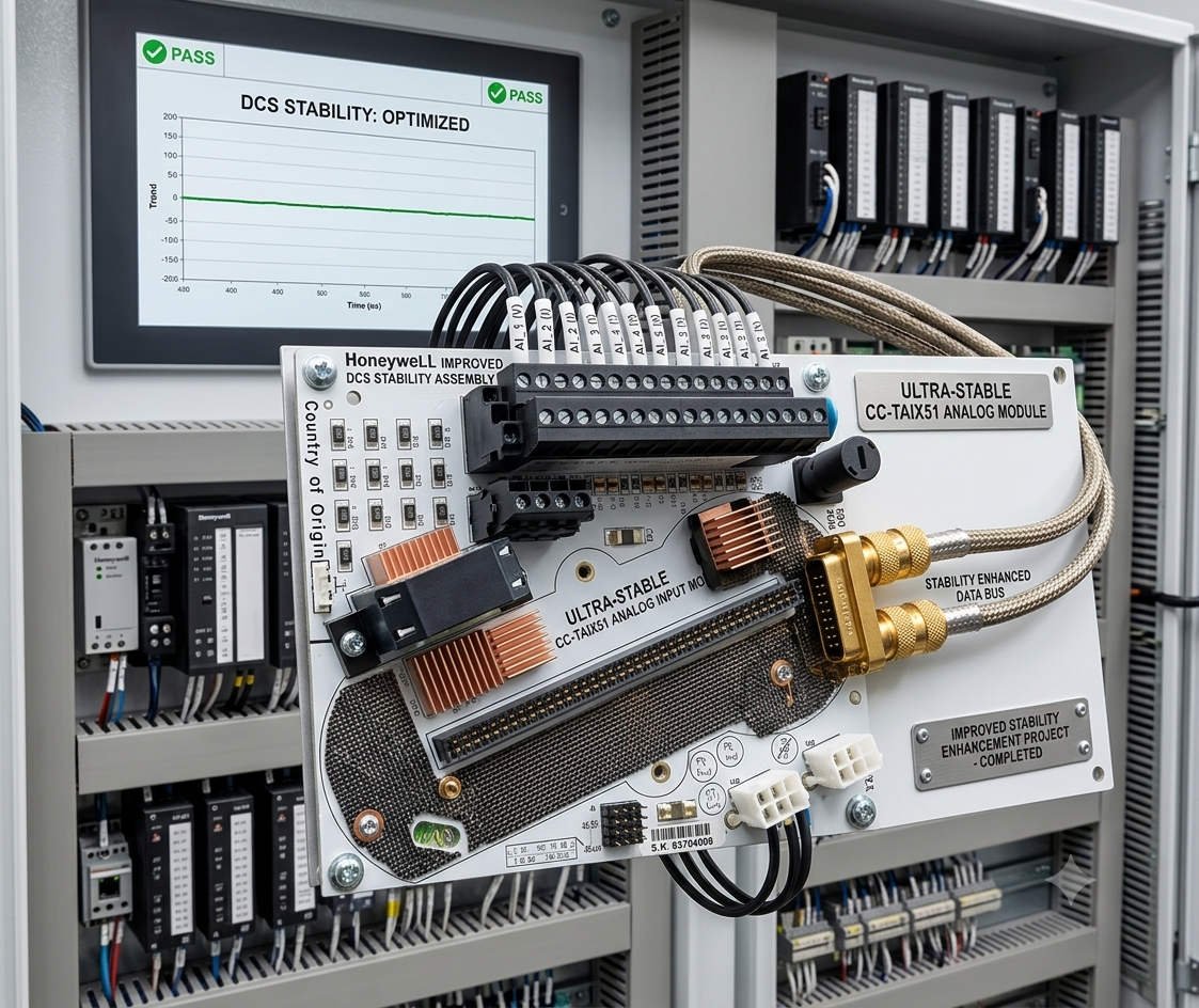
Honeywell CC-TAIX51 Guide: Solving Humidity-Induced Packet Loss

Reducing Packet Loss in Honeywell CC-TAIX51 Analog Input Modules

The Importance of Precision in Critical Process Industries

The Honeywell CC-TAIX51 analog input module provides high-precision signal acquisition for complex Distributed Control Systems (DCS). It serves vital sectors like oil & gas, pharmaceuticals, and chemical processing. However, high-humidity environments often trigger unexpected communication packet loss. This issue undermines system reliability and causes delayed control responses. Understanding these environmental triggers helps engineers prevent intermittent faults and maintain continuous production cycles.

How Micro-Condensation Disrupts Factory Automation Hardware

Standard industrial ratings often cover humidity levels up to 95% non-condensing. Nevertheless, rapid temperature shifts inside control cabinets create micro-condensation on PCB surfaces. Moisture forms conductive paths between sensitive communication traces. Consequently, this leads to signal distortion or transient short circuits. In fast PID control loops, even minor data acquisition delays can destabilize the entire process.

Maintaining Signal Integrity and Isolation Barriers

The CC-TAIX51 relies on high-impedance circuits to ensure accurate analog data. Humid conditions increase leakage current across these critical isolation barriers. As a result, insulation resistance drops and the signal-to-noise ratio (SNR) weakens. While analog values might only fluctuate slightly, the internal I/O link often suffers. This manifests as checksum failures and data retransmissions at the controller level.

Protecting High-Speed Backplane Communication Stability

These modules communicate with the DCS controller via high-speed backplane interfaces. Humidity and airborne contaminants quickly oxidize these metal connectors. Increased contact resistance introduces timing jitter or bit errors during data transfer. Therefore, communication drops occur more frequently under high system loads. Regular hardware inspection remains the best defense against these physical layer failures.

Optimizing Control Cabinet Climate Management

Field experience shows that climate control is more effective than simple sealing. We recommend installing anti-condensation heaters inside every critical cabinet. Technicians should maintain the internal temperature at least 5°C above the ambient dew point. Sealed IP-rated enclosures without thermal regulation often trap moisture inside. Proper airflow management ensures long-term reliability for all factory automation components.

Implementing Conformal Coating and Connector Care

For offshore or coastal installations, factory-applied conformal coating provides essential protection. Ensure all coatings comply with the IEC 61086 standard for industrial electronics. During maintenance shutdowns, use non-residue contact cleaners on backplane connectors. Re-seating modules restores proper contact pressure and clears oxidation. Powergear X Automation observers suggest that many “failed” modules only require professional cleaning to resume service.

Expert Analysis from Powergear X Automation

At Powergear X Automation, we believe environmental management defines hardware lifespan. The CC-TAIX51 is a robust component, but it cannot overcome poor cabinet design. Engineers should prioritize proactive thermal monitoring over reactive module replacement. Combining high-quality Honeywell hardware with rigorous maintenance standards significantly reduces total cost of ownership. Visit our website for more technical solutions and high-reliability automation hardware.

Technical Maintenance Checklist

  • 🔧 Install internal heaters to prevent micro-condensation.
  • 🔧 Maintain temperature 5°C above the local dew point.
  • 🔧 Use gold-plated or sealed connectors in high-corrosion zones.
  • 🔧 Verify firmware compatibility before swapping legacy modules.
  • 🔧 Schedule annual connector cleaning with non-residue agents.

Solution Scenario: Coastal Refinery Deployment

  • The Challenge: Intermittent “I/O Link Failure” alarms during morning temperature shifts.
  • The Discovery: Micro-condensation on the backplane due to high ambient salt-mist humidity.
  • The Fix: Installed regulated heaters and switched to conformal-coated CC-TAIX51 units.
  • The Result: Communication packet loss dropped to zero within the first 30 days.

Frequently Asked Questions

Q1: Why does my DCS report packet loss when the module seems powered on?
Communication requires much higher signal purity than simple power delivery. Humidity increases contact resistance, causing “bit-flip” errors that the DCS rejects as invalid packets. Powergear X recommends checking the backplane pins for discoloration first.

Q2: Is it better to replace an old module or improve cabinet cooling?
If the environment exceeds 95% humidity, a new module will eventually fail too. Improve the cabinet climate control first. However, if the old module shows visible corrosion on the gold fingers, replacement is necessary to prevent damaging the backplane.

Q3: How do I verify if my CC-TAIX51 is compatible with a legacy rack?
Always check the Honeywell hardware compatibility matrix for your specific firmware revision. Older racks may lack the modern shielding required for high-speed digital communication. In humid plants, consider upgrading the I/O base along with the module.

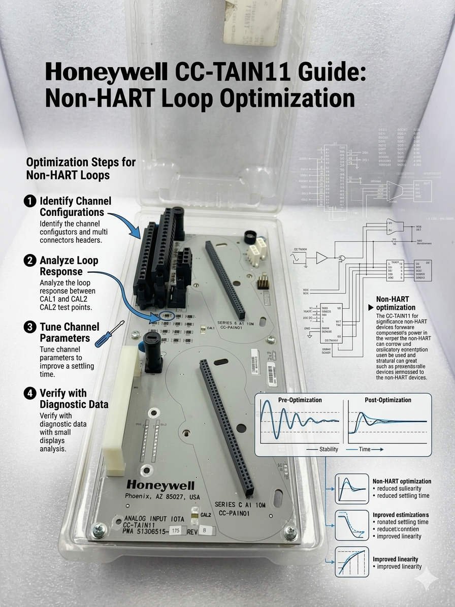
Honeywell CC-TAIN11 Guide Non-HART Loop Optimization

Honeywell CC-TAIN11 Guide: Non-HART Loop Optimization

Optimizing Honeywell CC-TAIN11 Performance for Non-HART Analog Loops

The Role of CC-TAIN11 in Modern DCS Architecture

The Honeywell CC-TAIN11 base provides essential termination for analog signals within Distributed Control Systems (DCS). It ensures stable data transmission for critical processes in the petrochemical and pharmaceutical sectors. However, engineers often face challenges when integrating non-HART field instruments. Maintaining 4–20 mA signal integrity remains the top priority for system reliability. Improper termination frequently leads to signal drift or control loop instability during high-demand operations.

Honeywell CC-TAIN11 Guide Non-HART Loop Optimization

Honeywell CC-TAIN11 Guide Non-HART Loop Optimization

Understanding HART vs. Non-HART Signal Requirements

Standard HART-enabled loops require a 250 Ω resistance to support digital communication over analog signals. For non-HART instruments, this digital layer does not exist. Adding an extra resistor in these cases is usually unnecessary. Moreover, redundant resistors increase the voltage drop across the circuit. This may reduce the overall accuracy of your factory automation sensors. Therefore, you must verify the input impedance of your AI module before modifying the hardware.

Managing Loop Resistance and Signal Saturation

Every 4–20 mA loop has a maximum load capacity, typically between 500 Ω and 750 Ω. If the total resistance exceeds the transmitter’s limit, the signal may saturate at high current levels. This saturation causes incorrect process readings during peak flow or pressure conditions. As a result, critical safety systems might fail to trigger appropriately. Always calculate the total budget of your loop resistance to ensure linear performance across the entire range.

Redundancy in Honeywell AI Module Design

Most modern Honeywell analog input modules already include precision internal resistors. These components handle the current-to-voltage conversion internally. Consequently, adding external resistors to the CC-TAIN11 is often redundant for standard transmitters. While legacy systems might require impedance matching, modern DCS platforms simplify this process. We recommend checking the specific technical manual for your AI module to confirm its internal configuration.

Best Practices for Field Commissioning and Maintenance

Success in the field requires a methodical approach to loop validation. Powergear X Automation suggests following these technical steps to ensure peak performance:

  • ✅ Use a calibrated multimeter to measure total loop resistance.
  • ✅ Verify the compliance voltage of the field transmitter.
  • ✅ Ensure single-point grounding to prevent EMI-induced fluctuations.
  • ✅ Inspect shield continuity for cable runs exceeding 300 meters.
  • ✅ Confirm the AI module impedance before adding any hardware.

Strategic Insights from Powergear X Automation

Our team at Powergear X Automation observes that 90% of signal issues stem from over-engineering. Many technicians add resistors by default without performing loop calculations. This habit often creates “ghost” faults that are difficult to diagnose later. We believe that a leaner, data-driven installation approach improves long-term stability. Always prioritize the manufacturer’s loop diagrams over generic field assumptions.

Practical Solution Scenarios

  • Refinery Long-Distance Loops: Minimizing resistance in 500m runs to prevent transmitter power failure.
  • Pharmaceutical Batch Control: Ensuring high-precision 4-20mA feedback without digital noise interference.
  • Heavy Industrial EMI Zones: Utilizing the CC-TAIN11 with robust shielding to protect sensitive analog data.

Expert FAQ: CC-TAIN11 Implementation

Q1: Will adding a 250 Ω resistor improve signal stability for non-HART devices?
Actually, it usually does the opposite. If your AI module already has an internal resistor, adding another one creates a parallel or series load that distorts the signal. Only add a resistor if your specific receiving equipment lacks an internal 250 Ω impedance.

Q2: How do I identify a “saturated” loop during plant startup?
Watch for signals that “flat-line” at roughly 18-19 mA even when process conditions increase. This typically indicates that the transmitter cannot push enough voltage through the high loop resistance. Removing unnecessary resistors on the CC-TAIN11 often fixes this immediately.

Q3: Can I use the CC-TAIN11 for third-party PLC integration?
Yes, but you must validate the wiring topology. Third-party PLCs often have different input impedances than Honeywell systems. Always perform a Loop Check (FAT) to ensure the 4-20mA scaling matches between the field device and the controller.

For high-quality components and expert technical support, visit the Powergear X Automation website for all your industrial automation needs.

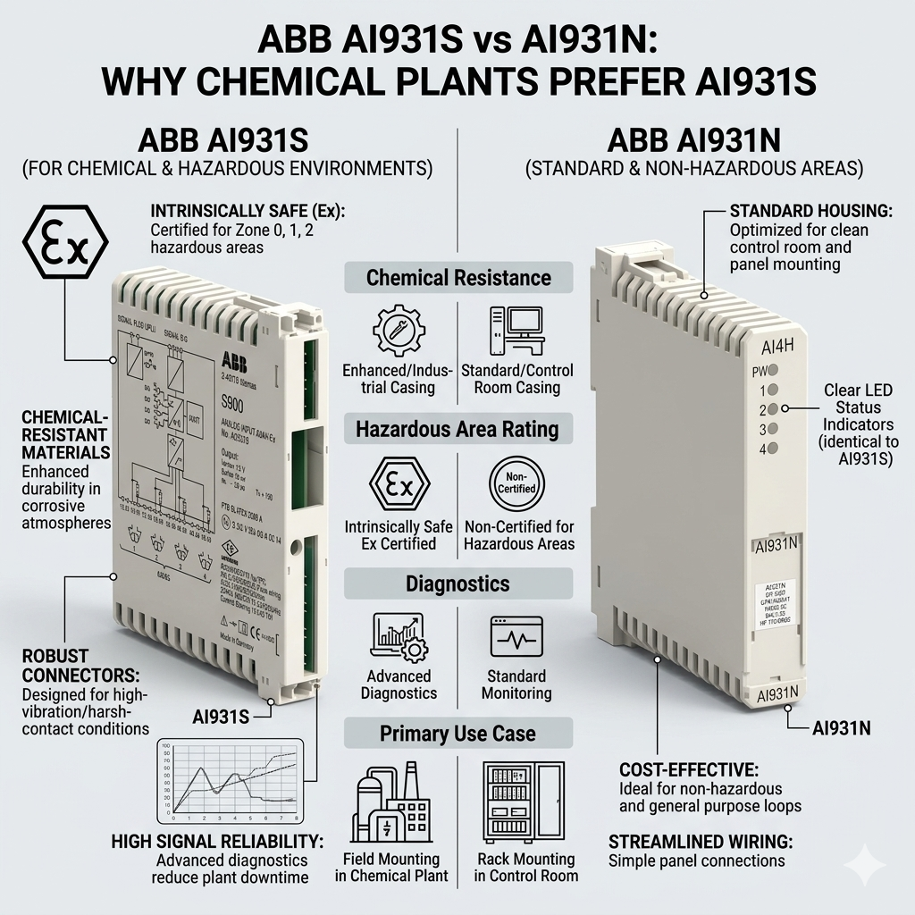
ABB AI931S vs AI931N: Why Chemical Plants Prefer AI931S

ABB AI931S vs AI931N: Why Chemical Plants Prefer AI931S

Comparison Guide: Why ABB AI931S Outperforms AI931N in Chemical Industry DCS Applications

In the demanding environment of industrial automation, analog signal integrity determines the success of process control. The ABB Symphony series utilizes the AI931 series for critical data acquisition. Engineers frequently choose the AI931S over its sibling, the AI931N. This preference stems from the module’s superior ability to handle corrosive atmospheres and electrical noise. While both capture 4–20 mA signals, the “S” variant offers technical advantages that ensure long-term plant uptime.

ABB AI931S vs AI931N: Why Chemical Plants Prefer AI931S

ABB AI931S vs AI931N: Why Chemical Plants Prefer AI931S

Superior EMC Resistance for Stable Control Systems

Chemical plants operate massive motors and variable frequency drives (VFDs) that generate significant electromagnetic interference. Standard analog modules often suffer from signal drifting or intermittent spikes in these zones. However, the AI931S features enhanced Electromagnetic Compatibility (EMC) immunity. It effectively filters transient noise during heavy machinery switching events. Consequently, PID loops remain stable, and operators avoid the “ghost alarms” that plague lower-spec hardware. Tighter signal control directly reduces the risk of off-spec chemical batches.

Operational Principles and Signal Acquisition Accuracy

The core function of the AI931 series involves converting field transmitter currents into digital values for the DCS. The AI931S employs high-resolution conversion circuits designed for modern, high-precision transmitters. It maintains accuracy even when instrumentation loops span long distances across a facility. Moreover, the internal isolation of the “S” model prevents ground loops from corrupting sensitive measurements. This technical design ensures that pH, pressure, and flow data remain reliable for critical safety interlocks.

Environmental Durability in Corrosive Factory Automation Zones

Chemical facilities expose control systems to corrosive vapors, high humidity, and temperature fluctuations. The AI931S is engineered with better environmental tolerance than the AI931N. It withstands moisture-heavy environments common in distillation and solvent handling areas. Furthermore, the module’s internal components resist the slow degradation caused by conductive dust. Investing in the “S” version reduces the frequency of unexpected I/O dropouts. As a result, maintenance teams spend less time on card replacements during emergency repairs.

Selecting Between AI931S and AI931N: Key Differences

The choice between these modules depends largely on the installation site’s electrical “cleanliness.” For indoor utility rooms with isolated wiring, the AI931N may suffice for basic monitoring. Conversely, the AI931S is the industry standard for outdoor marshalling cabinets or reactor areas. The price difference between the two is negligible compared to the cost of a single unplanned shutdown. Therefore, most DCS engineers prioritize the AI931S for its resilience. It provides a “fit and forget” solution for high-stakes chemical production.

Implementation Guidelines and Expert Recommendations

  • Cable Segregation: Keep analog signal wires at least 300mm away from high-power VFD feeders.
  • ⚙️ Grounding Protocols: Always terminate cable shields at the module side to eliminate dangerous ground loops.
  • 🔧 Environmental Control: Use anti-condensation heaters in outdoor cabinets to prevent terminal oxidation.

Perspective from Powergear X Automation Limited

At Powergear X Automation Limited, we believe that the trend toward “Smart” chemical plants requires higher hardware standards. As plants integrate more HART-enabled precision devices, the underlying I/O module must keep pace. We have observed that facilities upgrading to AI931S report a significant drop in intermittent signal faults. This shift reflects a broader industry move toward E-E-A-T (Expertise, Experience, Authoritativeness, and Trustworthiness) in hardware selection. To explore our full range of ABB Symphony components, please visit https://www.powergearx.com/ for reliable automation solutions.

Real-World Application Scenarios

In a large-scale ethylene reactor project, signal stability is non-negotiable. Using the AI931S for temperature acquisition ensures that the PID loop controlling the cooling jacket responds to real changes, not electrical noise. Similarly, in pharmaceutical batching, the high resolution of the AI931S allows for precise dosing of expensive ingredients. These scenarios demonstrate that selecting the right DCS module is as much about risk management as it is about electrical engineering.

Frequently Asked Questions (FAQ)

1. Can I mix AI931S and AI931N modules in the same ABB rack?
Yes, they are generally compatible within the same architecture. However, ensure your controller firmware is updated to recognize the specific diagnostic capabilities of the AI931S to maximize its value.

2. How does AI931S handle signal drift compared to older versions?
The AI931S uses advanced temperature compensation and better-shielded internal circuits. This design minimizes the thermal drift that often causes 4-20mA signals to deviate during seasonal weather changes.

3. What is the most common mistake when installing these modules?
The most frequent error is improper shielding. If the shield is grounded at both the transmitter and the AI931S module, it creates a ground loop that can negate the module’s built-in EMC protections.

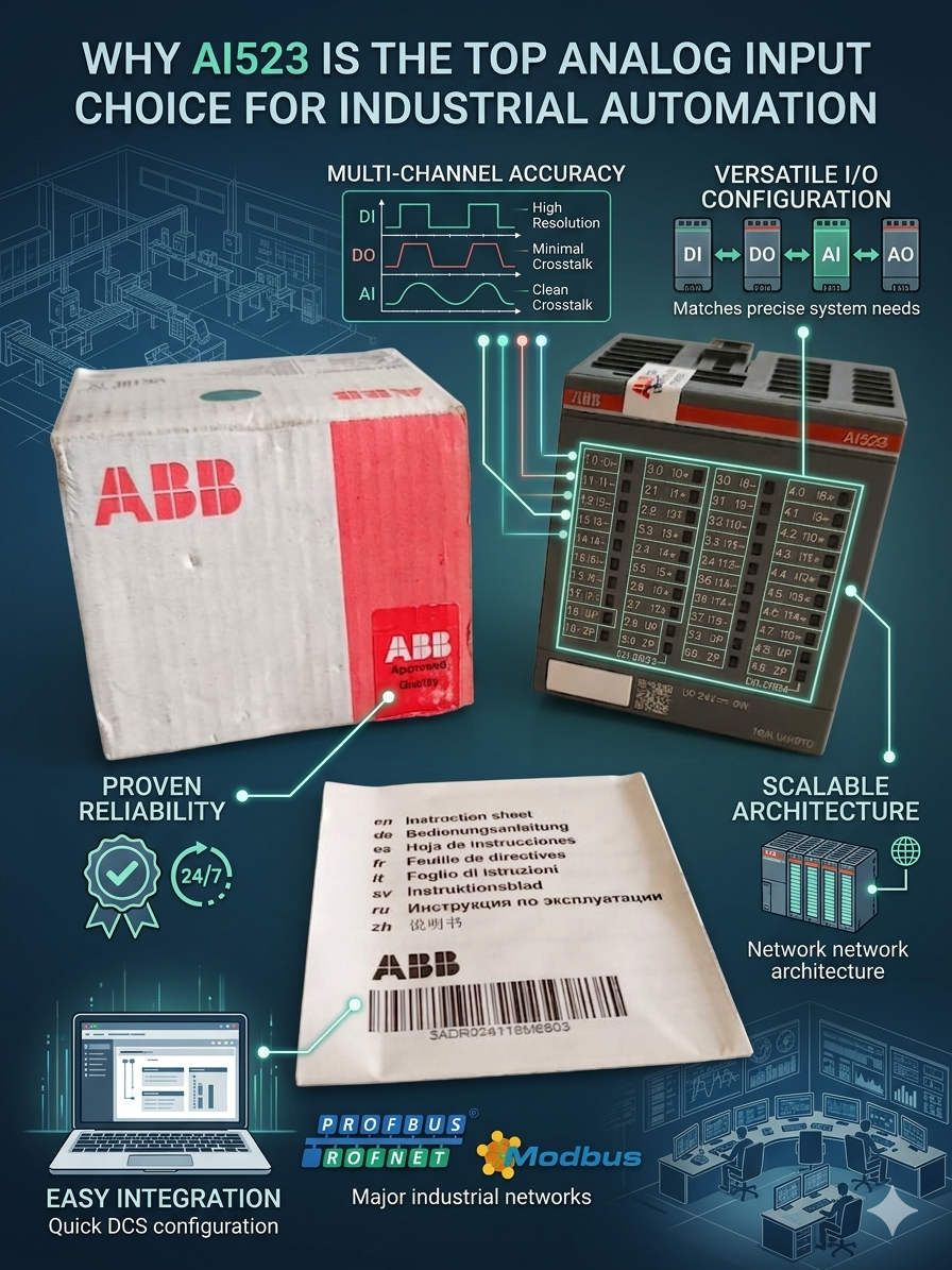
Why AI523 is the Top Analog Input Choice for Industrial Automation

Why AI523 is the Top Analog Input Choice for Industrial Automation
Is the AI523 the Most Versatile Analog Module in the AC500 Series?

In many industrial automation projects, the analog I/O layer often becomes a hidden bottleneck. Signal instability and poor channel isolation can cause significant delays during commissioning. The ABB AI523 analog input module addresses these practical integration challenges effectively. It eliminates the need for complex external signal conditioning hardware. Consequently, process industries such as chemical plants and water treatment facilities prioritize this module for its reliability and flexibility.

    Why AI523 is the Top Analog Input Choice for Industrial AutomationWhy AI523 is the Top Analog Input Choice for Industrial Automation

Multi-Signal Compatibility in Modern Control Systems

The AI523 stands out because it supports multiple industrial signal standards simultaneously. It handles both current and voltage-based instrumentation within a single architecture. In retrofit projects, this flexibility proves invaluable. Engineers often encounter mixed field devices, ranging from legacy 0–10 V sensors to modern 4–20 mA transmitters. Using the AI523 reduces the need for additional converters. Therefore, it simplifies cabinet design and minimizes potential failure points.

Signal Stability and Noise Immunity Technical Principles

Analog signal quality directly impacts the stability of any DCS or PLC system. In motor-heavy environments, electromagnetic interference often triggers false alarms. The AI523 utilizes advanced filtering and channel isolation to improve long-term reliability. This technical design is crucial when Variable Frequency Drives (VFDs) operate near I/O cabinets. Stable acquisition prevents PID oscillation and ensures accurate batch dosing. As a result, operators avoid chasing “ghost” faults caused by electrical noise.

Environmental Reliability for Factory Automation

Industrial environments subject hardware to heat, vibration, and humidity. The AI523 features a robust terminal structure designed for long operational cycles. Loose wiring often causes intermittent signal loss in high-vibration areas like compressor stations. This module provides secure connections that reduce unplanned maintenance. Furthermore, its thermal management allows for dense cabinet installations without compromising performance. Investing in durable hardware lowers the total cost of ownership over the plant’s lifecycle.

Strategic Maintenance and Installation Guidelines

  • Shielding Protocols: Ground analog cable shielding at one side only to prevent ground loops.
  • ⚙️ Mechanical Integrity: Use ferrules on stranded conductors to ensure maximum terminal contact.
  • 🔧 Surge Protection: Install dedicated surge protectors for any analog loops connected to outdoor instrumentation.

Authoritative Insight from Powergear X Automation Limited

At Powergear X Automation Limited, we believe that standardization is key to operational excellence. Standardizing on a universal module like the AI523 simplifies spare parts inventory. It also shortens the learning curve for maintenance technicians. We often see projects where inferior modules lead to hidden costs through intermittent downtime. Choosing the right interface is a strategic decision for any factory automation project. For a comprehensive range of ABB AC500 components, please visit our website at https://www.powergearx.com/.

Application Case: Pharmaceutical Process Skids

A recent pharmaceutical project required precise pressure and temperature monitoring across several skids. The engineers used the AI523 to integrate both legacy PT100 sensors and new HART-enabled transmitters. This approach allowed for a phased migration without halting production. The high-resolution acquisition ensured batch consistency and met strict regulatory standards. This case highlights how versatile I/O modules bridge the gap between different technology generations.

Frequently Asked Questions (FAQ)

1. How does the AI523 handle mixed active and passive current loops?
The module is adaptable, but you must plan your wiring carefully. We recommend verifying the power source for each loop. Proper distribution planning prevents overcurrent issues on the module’s backplane.

2. Can the AI523 be used in high-altitude energy facilities?
Yes, the AC500 series generally supports extended environmental ratings. However, check the derating curves for temperature and voltage isolation if your facility is above 2,000 meters.

3. What is the most common cause of “Input Overflow” errors on this module?
Overflow errors typically stem from a broken shield or an ungrounded signal reference. This causes common-mode voltage to drift beyond the module’s detectable range, even if the actual signal is correct.

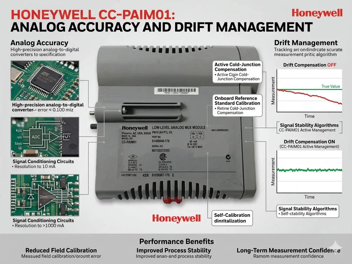
Honeywell CC-PAIM01 Analog Accuracy and Drift Management

Honeywell CC-PAIM01: Analog Accuracy and Drift Management

Maximizing Precision: The Role of Temperature Compensation in CC-PAIM01 Modules

The Critical Value of Thermal Stability in Analog Inputs

The Honeywell CC-PAIM01 analog input module plays a vital role in maintaining high-accuracy signal acquisition. In volatile industries like petrochemicals and pharmaceuticals, thermal drift can compromise process stability. Even minor temperature fluctuations can lead to measurement bias. Therefore, engineers must prioritize internal temperature compensation to ensure product quality. Accurate field calibration maintains signal integrity and prevents the need for premature hardware replacement.

Honeywell CC-PAIM01 Analog Accuracy and Drift Management

Honeywell CC-PAIM01 Analog Accuracy and Drift Management

Understanding the Impact of Temperature Drift Coefficients

While the CC-PAIM01 includes built-in compensation, environmental stress and component aging eventually introduce drift. A typical drift coefficient of ±0.01%/°C might appear insignificant at first glance. However, in high-precision flow or pressure loops, these errors accumulate quickly. As a result, uncompensated drift creates offset errors in 4–20 mA signals. This issue is particularly prevalent in outdoor cabinets that lack strict climate control.

Maintaining High-Resolution Signal Fidelity

Thermal stability directly influences the effectiveness of high-resolution A/D conversion. When temperatures shift, the resulting offset errors reduce the module’s effective resolution. This loss of fidelity can trigger unnecessary control loop oscillations in complex DCS environments. Moreover, advanced control strategies like tight-tolerance PID loops become less reliable. Consistent thermal management ensures that the module provides the granular data required for modern factory automation.

Professional Field Calibration Procedures

Successful calibration requires a stable environment and precise tools. Our team at Powergear X Automation recommends following these technical steps:

  • Isolate the input channel from the process.
  • Connect a precision signal source with ±0.005% accuracy.
  • Allow the module to thermally stabilize for 45 minutes.
  • Execute zero and span calibration via DCS engineering tools.
  • Apply multi-point checks at 4, 12, and 20 mA.

Strategic Cabinet Thermal Management

Hardware placement significantly affects long-term performance. Always install modules away from heat-generating components like power supplies or VFDs. Ideally, maintain cabinet temperature variations within a ±5°C range. In one refinery project, relocating a module 15 cm away from a heat source reduced alarms by 60%. Therefore, physical layout is just as important as software configuration for system reliability.

Expert Insights from Powergear X Automation

At Powergear X Automation, we believe technical discipline drives operational excellence. Many engineers misdiagnose grounding noise as temperature drift. Always verify your single-point grounding and use shielded twisted-pair cables before recalibrating. By combining proper installation with routine verification, you extend the lifecycle of your Honeywell assets while ensuring peak performance.

Technical Summary Checklist

  • ✅ Verify temperature compensation curves during commissioning.
  • ✅ Use precision calibrators for all analog loop checks.
  • ✅ Maintain strict physical separation from power cables.
  • ✅ Implement annual calibration for critical control loops.
  • ✅ Ensure firmware compatibility before replacing legacy modules.

Industrial Application Scenarios

  • Pharmaceutical Batch Processing: Maintaining strict temperature-dependent chemical reactions.
  • Oil and Gas Custody Transfer: Ensuring highly accurate flow measurements for billing.
  • Power Generation: Monitoring turbine pressure sensors in high-heat environments.

Implementation FAQ

Q1: When should I prioritize recalibration over module replacement?
If you notice a consistent offset that correlates with seasonal temperature changes, recalibration is the first step. Modules usually last over a decade, but their compensation curves may shift after 3 to 5 years of continuous operation.

Q2: How does the CC-PAIM01 handle extreme outdoor environments?
While rated for -20°C to +60°C, the module performs best when shielded from direct sunlight. We recommend using air-conditioned panels or sun shields to keep the internal cabinet temperature stable near 25°C.

Q3: What is the biggest mistake made during field calibration?
Skipping the thermal “warm-up” period is a common error. If you calibrate a cold module immediately after opening the cabinet, the settings will drift again as the module reaches its operating temperature.

For more technical guides and high-quality automation hardware, visit the Powergear X Automation website.

1769-IF4I vs 1769-IF4: Isolated vs Non-Isolated Analog Modules

1769-IF4I vs 1769-IF4: Isolated vs Non-Isolated Analog Modules

Choosing Between 1769-IF4I and 1769-IF4: A Guide to Analog Signal Integrity

Understanding the Role of Isolation in Industrial PLC Systems

Modern industrial automation demands high precision and equipment longevity. The Allen-Bradley 1769-IF4I serves as a robust shield against electrical noise and ground loops. In volatile sectors like chemical processing and oil & gas, this module protects the CompactLogix backplane. It ensures measurement stability for critical process variables. However, not every project requires high-level isolation. For cost-sensitive factory automation with short cable runs, the non-isolated 1769-IF4 offers an economical alternative. Engineers must evaluate the grounding risks before selecting a non-isolated path.

1769-IF4I vs 1769-IF4: Isolated vs Non-Isolated Analog Modules

Signal Integrity and Equipment Protection Mechanisms

The fundamental distinction between these modules lies in their electrical architecture. The 1769-IF4I features channel-to-channel and backplane isolation, whereas the 1769-IF4 utilizes a shared common reference. In high-noise environments near VFD-driven motors, non-isolated modules suffer from signal drift. This interference often triggers false alarms or destabilizes PID loops. Isolation prevents fault propagation across the system. It effectively safeguards both the controller and expensive upstream instrumentation from transient voltage spikes.

Impact of Electrical Noise on Process Control Accuracy

Both modules provide 16-bit resolution, yet real-world accuracy varies significantly based on noise immunity. Electrical interference effectively reduces the resolution of non-isolated setups. In precise dosing or pharmaceutical batching, even minor fluctuations lead to material waste. We observed a 2% fluctuation in a mixing skid using non-isolated inputs. Switching to the isolated 1769-IF4I eliminated this variation immediately. This proves that hardware-based isolation outperforms software-based filtering in high-stakes environments.

Balancing Conversion Speed and Control Responsiveness

While nominal update times appear similar, system-level responsiveness tells a different story. Non-isolated modules often require heavy software filtering to stabilize readings. Consequently, this adds latency to the control loop. For fast processes like gas pressure control, these delays compromise accuracy. Isolation reduces the need for aggressive filtering. As a result, the system maintains real-time responsiveness without sacrificing signal clarity.

Critical Installation and Grounding Strategies

If you choose the 1769-IF4, you must implement a disciplined electrical design. Proper grounding prevents the “floating ground” issues that cause intermittent analog spikes. Follow these technical requirements for non-isolated installations:

  • ✅ Use single-point grounding to prevent dangerous ground loops.
  • ✅ Separate analog signal cables from high-voltage power lines.
  • ✅ Avoid routing motor or heater loads in the same conduit.
  • ✅ Install DIN-rail surge protectors for outdoor or long-distance wiring.
  • ✅ Maintain recommended spacing to manage heat and EMI.

The Powergear X Automation Perspective on Engineering Value

At Powergear X Automation, we view the 1769-IF4I as more than a module; it is an insurance policy. While the 1769-IF4 is a practical choice for localized, well-grounded systems, the cost of troubleshooting one “ghost” signal often exceeds the initial savings. We recommend the isolated version for any application involving long-distance instrumentation or high EMI. In regulated industries like pharmaceuticals, stick to isolated designs to ensure GMP compliance and simplify system validation.

For more technical insights or to source high-quality Allen-Bradley components, visit our team at Powergear X Automation. We provide the expertise and inventory to keep your plant running efficiently.

Common Application Scenarios

  • Solution A (High Risk): Use 1769-IF4I for offshore rigs or refineries where lightning and motor noise are prevalent.
  • Solution B (Cost-Effective): Use 1769-IF4 for small, standalone packaging machines with sensors located within the same cabinet.

Frequently Asked Questions (FAQ)

Q1: Can I mix isolated and non-isolated modules on the same 1769 backplane?
Yes, the CompactLogix backplane supports both simultaneously. However, ensure your field wiring keeps the isolated and non-isolated signal commons physically separated to maintain the integrity of the isolated channels.

Q2: How do I know if my environment has too much EMI for a non-isolated module?
If your cabinet houses multiple Variable Frequency Drives (VFDs) or if your analog cables run longer than 15 meters, the risk of interference is high. In these cases, the isolated 1769-IF4I is the safer engineering choice.

Q3: What is the most common failure mode when downgrading to non-isolated inputs?
The most frequent issue is “signal jumping” or erratic readings caused by ground potential differences. If your sensors are powered from different sources, a non-isolated module will likely struggle with ground loop currents.

Troubleshooting Schneider 140AVI03000 Broken Wire Faults

Modicon 140AVI03000 Guide: Analog Input & Loop Diagnostics

Understanding Broken Wire Detection Logic

The Schneider Electric 140AVI03000 analog input module serves as a cornerstone for signal acquisition in high-stakes industrial automation. This Modicon Quantum component reliably captures low-level signals like 4–20 mA from various field instruments. In my experience at Powergear X Automation, we often see engineers treat “Broken Wire” alarms as simple hardware glitches. However, this diagnostic feature is a critical safety tool that prevents process deviations in oil, gas, and pharmaceutical sectors.

The 140AVI03000 utilizes advanced loop supervision to monitor input current levels continuously. When the current falls below a specific threshold, typically 3.5 mA, the module triggers a fault. This mechanism ensures the PLC does not mistake a failed sensor for a valid low process reading. Consequently, operators can trust that their flow or pressure data reflects actual field conditions.

Troubleshooting Schneider 140AVI03000 Broken Wire Faults

Enhancing System Stability Through Input Isolation

Electrical noise from Variable Frequency Drives (VFDs) or large motors often plagues industrial environments. The 140AVI03000 offers robust channel-to-bus isolation to combat these interference issues. This isolation prevents ground loops and induced noise from causing momentary current drops. Without this protection, control systems frequently suffer from “ghost” alarms that disrupt production cycles.

Avoiding Common Wiring Topology Errors

Compatibility with both 2-wire and 4-wire transmitters makes this module versatile for factory automation. Nevertheless, technicians often confuse the power sourcing requirements during the commissioning phase. The 140AVI03000 does not always provide loop power for every configuration. Misunderstanding this distinction remains a leading cause of immediate Broken Wire faults upon system startup.

Proven Field Strategies for Maintenance and Reliability

Statistical data suggests that over 60% of analog signal failures stem from external wiring rather than internal module defects. Before replacing expensive hardware, follow these field-tested steps:

Measure the loop current using a high-precision multimeter.

Verify the external 24 VDC supply for all 4-wire transmitters.

Confirm that the wiring polarity matches the official Schneider diagrams.

Check terminal tightness, especially in high-vibration areas like pump skids.

Install ferrules on all analog signal wires to ensure permanent contact.

Optimizing Shielding and Grounding Standards

Improper grounding often creates intermittent faults that are difficult to diagnose. Experts follow IEC 61158 standards by grounding the cable shield at only one end. Usually, the control cabinet serves as the best single-point ground location. Floating shields or multiple ground points create circulating currents, which mimic the symptoms of a physical break in the wire.

Author Insights: The Future of Analog Diagnostics

At Powergear X Automation, we believe that proactive diagnostics like those in the 140AVI03000 are non-negotiable for modern DCS and PLC architectures. While digital protocols like HART or Foundation Fieldbus are growing, the 4–20 mA standard remains the industry’s backbone. Investing in modules with “Broken Wire” detection ensures your facility meets the traceability requirements of highly regulated industries.

Application Scenarios

  • Chemical Processing: Monitoring hazardous pressure levels where signal loss could lead to tank overpressure.
  • Water Treatment: Ensuring continuous flow data for chemical dosing pumps to maintain water quality.
  • Oil & Gas Skids: Providing reliable feedback in high-vibration environments near large compression units.

Technical Best Practices Checklist

  • ✅ Use shielded twisted-pair cables for all low-level analog signals.
  • ✅ Separate signal cables from high-voltage power lines by at least 30cm.
  • ✅ Implement software filtering to ignore sub-millisecond signal transients.
  • ✅ Document all loop resistance values during the initial commissioning phase.
  • ✅ Test the module annually using a calibrated 4-20 mA loop simulator.

Frequently Asked Questions (FAQ)

Q1: How can I distinguish between a sensor failure and a module channel failure?

The most effective method is the “Channel Swap” test. Move the suspected field wire to a known working channel on the module. If the error moves with the wire, the issue lies in the field. If the error stays on the original channel, the 140AVI03000 hardware may require repair.

Q2: Does this module require specific configuration in EcoStruxure Control Expert?

Yes, you must enable the “Broken Wire” detection feature within the hardware configuration shortcut. If you use a 0–20 mA scale instead of 4–20 mA, you should disable this feature. A 0 mA signal is “normal” for 0-20 mA loops, which would trigger false alarms.

Q3: Can I use the 140AVI03000 for high-accuracy temperature measurements?

While this module handles 4-20 mA signals from temperature transmitters, it is not a direct RTD or Thermocouple module. For maximum accuracy, ensure your transmitter is calibrated. The module’s 12-bit to 16-bit resolution (depending on settings) is generally sufficient for most industrial thermal processes.

For more technical guides, high-quality PLC components, and expert automation support, visit Powergear X Automation. We help you optimize your control systems for maximum uptime.

Maximizing Precision with Quantum 140ATI03000C Analog Inputs

Maximizing Precision with Quantum 140ATI03000C Analog Inputs

Optimizing Signal Precision with the Modicon Quantum 140ATI03000C Analog Input Module

The Modicon Quantum 140ATI03000C serves as a cornerstone for stable signal acquisition in demanding industrial environments. In chemical plants and oil and gas facilities, precision is non-negotiable. This high-density analog input module converts critical low-level signals into actionable PLC data. However, achieving peak performance requires more than just installation. It demands a deep understanding of wiring integrity and grounding principles to prevent data corruption.

Maximizing Precision with Quantum 140ATI03000C Analog Inputs

Enhancing Control with High-Resolution Signal Conversion

The 140ATI03000C excels at high-resolution analog-to-digital conversion for 4–20 mA and ±10 V loops. This precision is vital for maintaining tight control over flow, pressure, and temperature variables. Nevertheless, higher sensitivity often makes the system more vulnerable to electromagnetic interference (EMI). At Powergear X Automation, we frequently observe “fluttering” values in the field. These fluctuations usually stem from unshielded cables placed too close to Variable Frequency Drives (VFDs).

The Critical Role of Channel Isolation and Grounding

Engineered to meet IEC 61131-2 standards, this module provides robust isolation across its input channels. Despite this design, performance depends heavily on localized grounding practices. If a potential difference exists between the field instrument and the PLC ground, common-mode noise emerges. This noise often manifests as random data spikes or persistent signal drift. Experienced technicians know that a missing single-point ground can easily mimic a hardware failure.

Maintaining Long-Term Reliability in Harsh Environments

The Quantum platform is renowned for its industrial-grade durability and EMC tolerance. Even so, environmental stressors like high humidity or aging terminal blocks can degrade performance. Intermittent channel errors often signal a gradual decline rather than a sudden catastrophic failure. Early detection of these anomalies prevents unplanned shutdowns. Furthermore, monitoring signal health ensures that safety interlocks do not trigger based on false or noisy data.

A Disciplined Maintenance and Diagnostic Strategy

When troubleshooting erratic readings, engineers must distinguish between external interference and internal hardware degradation. A systematic approach saves time and reduces unnecessary replacement costs. We recommend the following diagnostic and preventative steps:

  • Execute a Signal Swap Test: Move the suspect signal to a known-functional channel. Observe if the fluctuation follows the field wiring. Identify if the error remains on the original channel.
  • Implement Shielding Best Practices: Utilize twisted, shielded cables for all analog inputs. Ground the shield exclusively at the PLC side. Maintain a 200 mm gap from power cables.
  • Install External Surge Suppression: The 140ATI03000C lacks comprehensive built-in surge protection. Add external protectors for outdoor or high-induction areas. Prevent cumulative damage from frequent atmospheric surges.

Expert Insight from Powergear X Automation

In my professional view, the 140ATI03000C remains one of the most reliable modules in the industrial automation market. Most “failures” reported by users are actually environmental or installation-related issues. By focusing on EMI mitigation and proper cable routing, you can extend the lifecycle of your control systems significantly. Investing in high-quality shielding today prevents costly downtime tomorrow.

For more technical guides and premium Modicon components, visit Powergear X Automation.

Industrial Application Scenarios

  • Chemical Batch Processing: Monitoring exothermic reactions where even a 0.5% temperature deviation impacts product quality.
  • Oil & Gas Pipelines: Collecting long-distance pressure data where ground loops are common challenges.
  • Water Treatment Facilities: Integrating flow meters that are often exposed to external lightning risks.

Frequently Asked Questions

How can I tell if my module is failing or if it is just a noise issue?
If a single channel shows erratic behavior while others remain stable, perform a swap test. If the noise persists on the same channel regardless of the signal source, the internal circuitry is likely compromised.

What should I check when upgrading from older Quantum variants?
Always verify firmware compatibility within EcoStruxure Control Expert. Additionally, recalibrate your scaling parameters, as older modules may have different internal offsets that affect measurement accuracy.

Is it necessary to use a signal isolator with this module?
While the 140ATI03000C has internal isolation, adding external signal isolators is wise for high-risk loops. This provides an extra layer of protection for the module’s backplane against massive field surges.

Honeywell CC-PAIH01 vs CC-PAIH51: Technical Comparison

Honeywell CC-PAIH01 vs CC-PAIH51: Technical Comparison

Honeywell CC-PAIH01 vs. CC-PAIH51: Maximizing C300 System Reliability

In the world of industrial automation, hardware choices determine long-term plant stability. Field engineers often view the CC-PAIH01 and CC-PAIH51 as interchangeable High-Level Analog Input (HLAI) modules. These components share the same physical form factor for the Honeywell C300 controller. However, the CC-PAIH51 represents a significant leap in hardware diagnostics and thermal efficiency. Our team at Powergear X Automation has analyzed these differences to help you prevent unscheduled downtime.

Honeywell CC-PAIH01 vs CC-PAIH51: Technical Comparison

The Role of HLAI Modules in Process Control

The CC-PAIH01 and CC-PAIH51 modules serve as the primary interface for field transmitters. They convert 4-20mA signals into digital data for the C300 controller. These modules must maintain millisecond-level accuracy in harsh refinery or chemical plant environments. While both units perform basic signal conversion, the CC-PAIH51 addresses critical “blind spots” found in older hardware. Consequently, this newer version provides better protection against loop shutdowns.

Advanced Internal Diagnostics for Predictive Maintenance

The “51” series offers superior self-testing capabilities compared to the legacy “01” model. In a standard DCS environment, a CC-PAIH01 failure often results in an immediate “Bad PV” (Process Variable) alarm. This sudden failure can trigger an emergency trip. Conversely, the CC-PAIH51 detects internal component degradation before a total failure occurs. This early warning allows technicians to perform a planned hot-swap. As a result, plants maintain higher availability and safety standards.

Enhanced HART Communication and Signal Stability

Both modules support HART (Highway Addressable Remote Transducer) digital communication. However, the CC-PAIH51 features improved impedance matching for modern field devices. This technical refinement is vital for cable runs exceeding 300 meters. Poor impedance matching often causes “ghost” device alerts in the Field Device Manager (FDM). Moreover, the CC-PAIH51 ensures a cleaner data path for complex multi-variable transmitters, such as Coriolis meters.

Thermal Management and Component Longevity

Heat is the primary enemy of electronics in crowded control cabinets. Industry data suggests that a 10°C rise in temperature can halve the lifespan of electrolytic capacitors. The CC-PAIH51 utilizes updated power management components that reduce heat output. These modules typically run 2°C to 3°C cooler than the CC-PAIH01. Therefore, upgrading to the “51” series significantly extends the Mean Time Between Failures (MTBF) for your control system.

Critical Field Rules for IOTA Compatibility

Engineers must exercise caution when managing I/O Termination Assemblies (IOTA). Both modules utilize the CC-TAIH01 or CC-TAIH11 IOTAs. However, you should never mix an ’01’ and a ’51’ on the same redundant pair. Internal timing differences can cause synchronization errors during a controller switchover. Additionally, always verify shield grounding at the marshalling panel. Proper grounding prevents ground loops from damaging sensitive A/D converters in these modules.

Strategic Guide for Hardware Upgrades

Is the CC-PAIH51 a direct replacement for the CC-PAIH01? The answer is yes, but the upgrade requires software synchronization. If the Experion PKS Engineering Studio expects an ’01’ module, it will flag a “Model Mismatch” error. You must update the configuration to recognize the new hardware. Since the CC-PAIH01 is increasingly rare, we recommend the CC-PAIH51 for all new installations. This ensures your system is ready for modern digital transformation initiatives.

Technical Summary Table

FeatureCC-PAIH01 (Legacy)CC-PAIH51 (Modern)
Diagnostic DepthBasic (Fail-only)Advanced (Predictive)
Thermal EfficiencyStandardHigh (2-3°C Cooler)
HART StabilityModerateOptimized for Long Runs
RedundancyRequires Matched PairRequires Matched Pair
StatusLimited AvailabilityStandard Production

Solution Scenario: Reducing Nuisance Alarms

A mid-sized chemical plant recently experienced frequent “Ghost Alarms” on their long-distance pressure loops. The existing CC-PAIH01 modules struggled with signal attenuation and interference. By migrating to CC-PAIH51 modules and optimizing the IOTA shielding, the plant eliminated 95% of signal noise. This change allowed the asset management software to receive clean, high-speed data for predictive analytics.

To optimize your control system hardware and secure reliable components, visit the experts at Powergear X Automation.

Frequently Asked Questions (FAQ)

1. Can I use a CC-PAIH51 module with an older C200 controller?
No, these specific CC-prefix modules are designed for the C300 controller and the Series C I/O platform. They are not compatible with the older C200 or PMIO hardware.

2. Does the CC-PAIH51 require a different terminal block?
No, it uses the same IOTA (Input Output Termination Assembly) as the CC-PAIH01. This makes the physical hardware swap very simple during maintenance windows.

3. Why does my system show a “Model Mismatch” after swapping the module?
This occurs because the Experion software configuration is still set to the CC-PAIH01 model. You must update the I/O module type in Engineering Studio to clear the alarm.

Back to Top
Product has been added to your cart