Is the 1769-L23E-QBFC1B Expandable? Expansion Cable Guide
Understanding the 1769-L23E-QBFC1B: Limits of Expansion Cables and I/O Architecture
The Core Design of Integrated CompactLogix Systems
The 1769-L23E-QBFC1B stands as a cornerstone for small-scale industrial automation. Rockwell Automation designed this specific CompactLogix model to streamline engineering time. It merges the CPU, power supply, and diverse I/O points into a single, fixed housing. This “all-in-one” approach benefits machine builders who require a smaller cabinet footprint. However, users must understand the hardware’s structural boundaries before finalizing a system design.

Can You Connect Additional 1769 Modules via Expansion Cables?
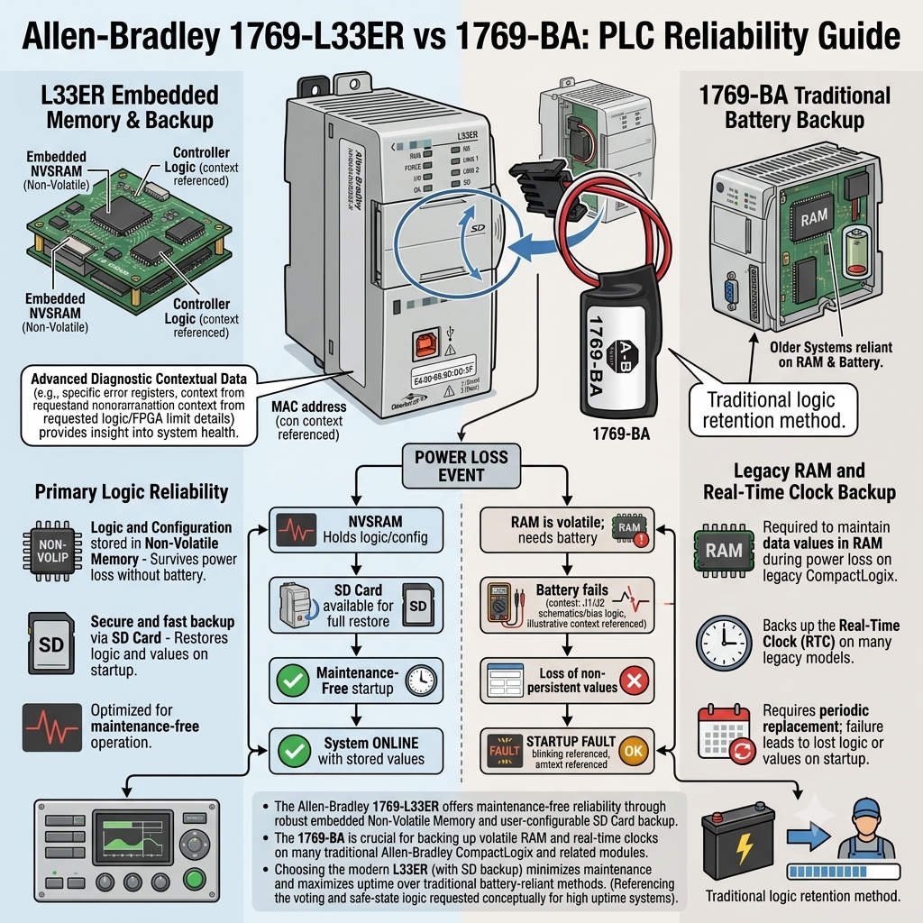
A frequent question in factory automation involves the use of 1769-CRR1 or 1769-CLL1 expansion cables with this unit. The answer is no. The 1769-L23E-QBFC1B features a fixed I/O architecture. It does not possess the right-side bus interface required to connect additional local 1769 modules. Therefore, you cannot physically extend the backplane to accommodate more digital or analog cards. This hardware limitation distinguishes the L23 series from more modular counterparts like the L30 or L33ER series.
Leveraging EtherNet/IP for System Scalability
Although local expansion is restricted, the integrated EtherNet/IP port offers a powerful alternative for growth. Engineers can scale their control systems by deploying distributed I/O blocks or remote adapters. According to MarketsandMarkets, the industrial Ethernet market continues to grow as plants move toward decentralized control. By using the ODVA-standard EtherNet/IP protocol, this controller manages networked drives and remote sensors efficiently. This method often proves more flexible than traditional ribbon-cable expansion in modern PLC environments.
Strategic Selection: Fixed vs. Modular Controllers
Choosing the right PLC involves balancing immediate costs against future flexibility. The 1769-L23E-QBFC1B excels in OEM equipment where the I/O count remains constant. For example, a standard labeling machine rarely needs more than the onboard high-speed counters and analog points. However, if your production line expects future upgrades, a modular controller is safer. In those cases, opting for a system that supports physical expansion cables prevents a total hardware rip-and-replace later.
Author Insights from PLCDCSHUB
At PLCDCSHUB, we often see commissioning delays caused by “expansion surprises.” Many technicians assume all 1769-labeled products share the same bus capabilities. We recommend always verifying the “Right-End Cap” compatibility before purchase. If your project demands high-speed deterministic execution across multiple racks, the L23 series might be too restrictive. For the best selection of genuine automation hardware and technical support, visit PLCDCSHUB Limited to explore compatible alternatives.
Installation and Maintenance Best Practices
- ✅ Reserve Spare Capacity: Always leave at least 25% of the onboard I/O points open for emergency field changes.
- ✅ Vibration Management: Use industrial-grade shielded Ethernet cables to prevent packet loss in high-vibration zones.
- ✅ Firmware Alignment: Ensure your Studio 5000 or RSLogix 5000 version matches the controller’s major revision for stable communication.
- ✅ Environmental Shielding: Keep the integrated unit away from high-heat sources to prolong the life of the internal power supply.
Application Scenario: Precision Packaging Control
In a typical high-speed cartoning application, the 1769-L23E-QBFC1B manages the primary logic and integrated motion. The onboard high-speed counter tracks the conveyor encoder, while analog outputs control motor speeds. Because the machine design is standardized, the lack of expansion cables is an advantage—it prevents unauthorized field modifications that could destabilize the original timing. If a secondary feeder is added later, a remote Point I/O module via Ethernet provides the necessary link.
Frequently Asked Questions (FAQ)
Q: What happens if I run out of I/O points on an L23E during commissioning?
Since you cannot add local modules, you must either use an Ethernet-based remote I/O block (like 1734-AENT) or replace the controller with a modular L3 series unit. We suggest checking PLCDCSHUB for immediate stock on remote adapters.
Q: Does the lack of expansion cables affect the controller’s processing speed?
No. The processing power is dedicated to the fixed I/O and communication tasks. In fact, fixed I/O often results in slightly faster update times (RPI) because the data doesn’t have to travel across an external bus cable.
Q: Can I use the 1769-L23E-QBFC1B as a gateway for other PLCs?
Yes. Its EtherNet/IP port supports messaging (MSG instructions), allowing it to act as a data concentrator between older SLC 5/05 systems and newer ControlLogix architectures, provided they are on the same network subnet.
For more technical deep-dives and to procure high-quality industrial modules, visit our official site at PLCDCSHUB Limited.