Reliable DCS Performance: Yokogawa Modules in Harsh Environments
Optimizing Yokogawa Processor Performance in Extreme Thermal Environments
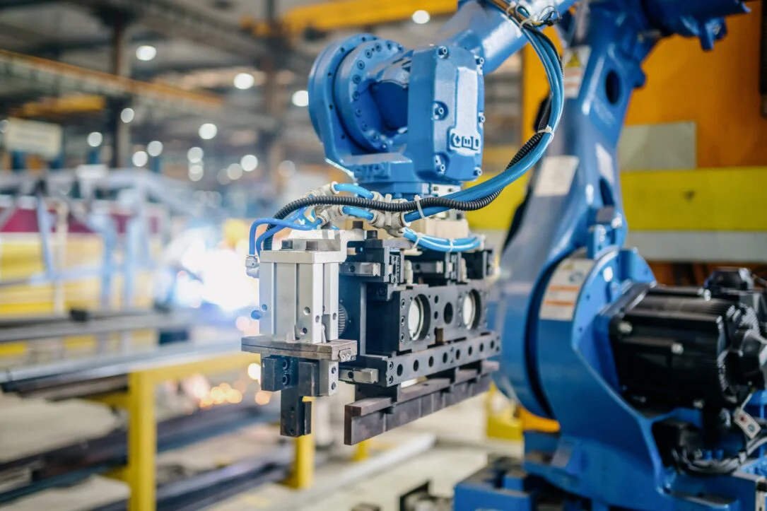
The Critical Role of Thermal Resilience in Industrial Automation
Modern industrial automation demands hardware that survives beyond controlled control rooms. In sectors like oil and gas or chemical processing, ambient temperatures often fluctuate wildly. Yokogawa processor modules for CENTUM VP and legacy CS 3000 systems address these challenges directly. These controllers ensure continuous operation and safety in non-ideal environments. Consequently, engineers can place control cabinets closer to the process area. This proximity reduces signal wiring length and enhances overall response reliability.

Technical Deep Dive: Achieving Deterministic Control at 70°C
Yokogawa engineers these modules to withstand a rigorous range from -20°C to +70°C. This specification is more than a marketing figure; it represents industrial-grade component selection. Most standard PLCs suffer from thermal throttling, which causes scan jitter. However, Yokogawa maintains stable execution cycles even at peak heat. This stability ensures consistent PID performance and predictable interlock timing. Such precision is vital for pharmaceutical batch processes where timing deviations impact regulatory compliance.
Maximizing System Longevity Through Strategic Derating
At Powergear X Automation, we observe that Yokogawa utilizes conservative component derating. This design choice significantly slows the thermal aging of CPUs and power regulators. While the hardware supports 70°C, we recommend maintaining internal cabinet temperatures below 55°C. Lower temperatures exponentially improve the Mean Time Between Failures (MTBF). Furthermore, passive ventilation often proves more reliable than small air conditioners in dusty or corrosive environments.
Installation Best Practices for Harsh Field Conditions
Reliable factory automation requires more than just high-spec hardware. Proper installation remains the foundation of system uptime. Consider these technical requirements:
- Stabilize cabinets above -10°C before performing a cold start.
- Use locking terminal blocks to prevent vibration-induced loosening.
- Avoid routing high-current cables near sensitive processor backplanes.
- Implement grounding according to IEC 61000-5-2 standards.
- Monitor mixed-generation nodes for thermal expansion issues.
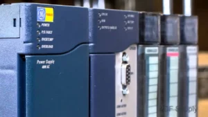
Strategic Upgrading: From CS 3000 to CENTUM VP
Transitioning from legacy CS 3000 to CENTUM VP offers significant thermal advantages. Older modules are robust, but newer processors utilize advanced semiconductor processes. These modern components provide better heat dissipation and enhanced onboard diagnostics. If your facility regularly exceeds 60°C, upgrading is a proactive safety measure. Always verify firmware alignment when integrating new processors with older I/O modules to prevent communication errors.
Real-World Application Scenarios
- Upstream Oil & Gas: Remote wellhead control in desert or arctic conditions.
- Chemical Processing: Outdoor utility plants with high radiant heat signatures.
- Offshore Platforms: Compact cabinets where dense I/O creates internal heat pockets.
Expert FAQ: Selection and Maintenance Insights
Q1: How do I choose between standard and wide-temperature rated modules for a new project?
Focus on the “Worst Case” internal cabinet temperature rather than the outside climate. If your cabinet lacks active cooling and houses high-density I/O, always opt for the extended range modules to prevent premature CPU aging.
Q2: Can I mix CENTUM VP processors with CS 3000 I/O in high-heat areas?
Yes, but exercise caution. While functionally compatible, older I/O modules often fail before the newer processors under thermal stress. We suggest auditing the heat tolerance of your oldest components before performing a partial upgrade.
Q3: What is the most common “hidden” failure cause in hot environments?
It is rarely the CPU itself. Instead, electrolytic capacitors in older power supply assemblies often dry out. If your system is over 10 years old, replace the power modules before pushing the system into high-temperature seasons.
Author’s Insight: Reliability in extreme temperatures is not just about survival; it is about maintaining predictable control for decades. For more technical guides and premium components, visit Powergear X Automation to optimize your control systems.