Bently Nevada 3500/42M Bypass LED Issue: Proximitor Wiring Guide
Why Reverse Proximitor Wiring Illuminates the Bypass LED on Bently Nevada 3500/42M Modules
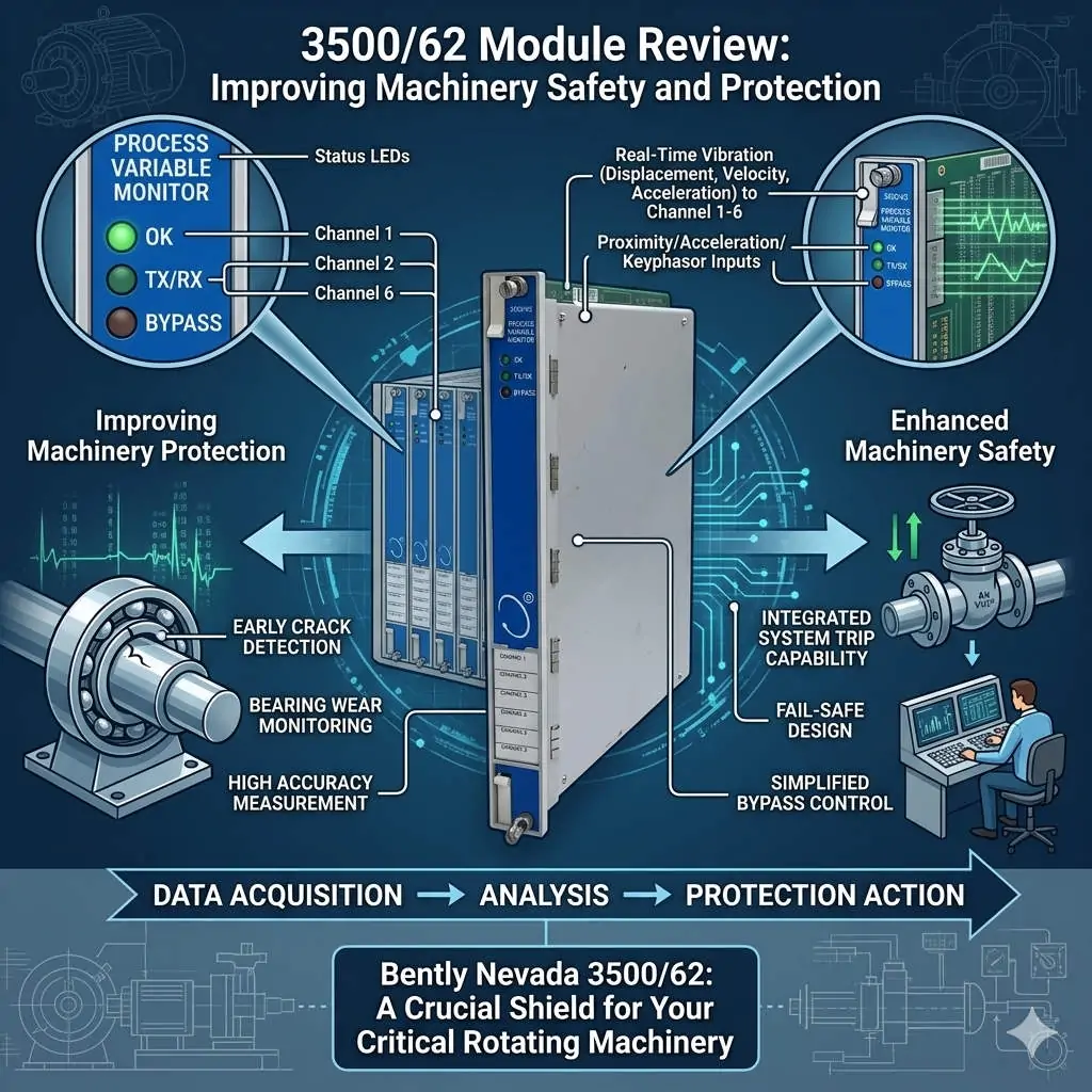
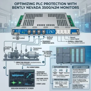
Precision machinery protection requires dependable sensors and advanced control systems in industrial automation. The Bently Nevada 3500/42M Proximity/Seismic Monitor module measures shaft vibration and displacement on critical turbomachinery. However, reversing polarity on eddy current Proximitor sensors creates unexpected behavior. The module activates the Bypass LED while the Alert LED remains dark. At Powergear X Automation, our technical team analyzes why polarity errors disrupt monitoring channels and explains how field engineers can resolve this issue efficiently.

Bently Nevada 3500-42M Bypass LED Issue Proximitor Wiring Guide_
The Core Role of Eddy Current Sensors in Machinery Protection
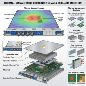
Rotating machinery in power generation and chemical plants relies on eddy current probes for real-time condition monitoring. The Proximitor sensor drives high-frequency radio signals through the probe tip to form an electromagnetic field. As the metal shaft moves, eddy current losses change the probe impedance. The Proximitor converts this impedance shift into a proportional DC voltage. The 3500/42M module processes this analog voltage to calculate shaft vibration amplitudes. Proper sensor operation allows plant operators to detect bearing wear and rotor unbalance before catastrophic failures happen.
Understanding the Impact of Reversed -24VDC Supply Polarity
Bently Nevada 3300 XL and 3500 proximity probe systems require a stable -24VDC power supply. Reversing terminal connections halts the internal active electronics within the Proximitor. Consequently, the sensor fails to produce a valid dynamic signal or a stable DC gap voltage. The output voltage floats near zero or clamps to an invalid rail level. B2B engineers must realize that the 3500/42M module cannot calculate real vibration data without a proper gap voltage. Therefore, the monitor inhibits alarm processing to prevent false plant trips.
Analyzing 3500/42M Bypass State Logic and Safety Design
The 3500/42M monitor features sophisticated onboard diagnostics rather than simple signal threshold detection. When an invalid input voltage occurs, internal logic marks the channel as Not OK. The monitor then suppresses alarm outputs and illuminates the Bypass LED. Field personnel often misinterpret this Bypass light as a software override. However, the system automatically enters this protective state when sensor signals fall outside valid operating ranges. This safety design ensures that unpowered or incorrectly wired sensors do not trigger accidental machine shutdowns.
Complete Diagnostic Checklist for Bently Nevada Channel Alerts
Illuminating the Alert LED on a 3500/42M module requires satisfying five distinct monitoring conditions in sequence:
- Correct Power Supply: The Proximitor must receive a steady -24VDC supply with correct polarity.
- Valid Gap Voltage: The probe must operate within its linear range, typically producing -8VDC to -10VDC at nominal gap.
- Healthy Channel Status: The 3500/42M module must register a Channel OK condition in internal memory.
- Active Alarm Logic: Software configuration must enable channel alerts without manual user bypass.
- Vibration Threshold Exceeded: Shaft vibration amplitude must exceed the programmed alert setpoint value.
Step-by-Step Commissioning and Troubleshooting Sequence
Engineers should follow a structured sequence when troubleshooting a Channel Not OK or active Bypass status:
- Verify Terminal Wire Definitions: Confirm connections at Terminal A (-24VDC), Terminal B (COM), and Terminal C (Signal OUT) instead of relying solely on wire colors.
- Measure Static Gap Voltage: Use a digital multimeter to measure DC voltage across COM and OUT terminals at the field junction box.
- Inspect System Event Logs: Connect via 3500 Rack Configuration Software to check for specific fault messages like Input Voltage Fault.
- Clear Software Bypass Overrides: Ensure maintenance teams clear all manual software bypass flags after completing field wiring corrections.
Field Installation Best Practices and Cable Shielding Rules
High-vibration machinery environments present severe electromagnetic noise from variable frequency drives and high-power motors. Signal cables must utilize twisted-pair construction with overall shielding. Engineers must connect the cable shield to ground at the control cabinet end only. Dual-ended shield grounding creates circulating earth loops, which introduce artificial electrical noise onto the -24VDC supply lines. Proper wiring practices protect delicate proximity signals and prevent false vibration alarms across factory automation networks.
B2B Procurement and Hardware Replacement Guidelines
Replacing legacy Bently Nevada Proximitors requires verifying technical specifications rather than assuming direct hardware equivalence. Procurement specialists must match probe diameters, system lengths, and scale factors. For example, mixing 5mm probes with 8mm Proximitor drivers shifts the output scale factor from 7.87 mV/um to incorrect levels. Modern 3300 XL components maintain backward compatibility with older 3500 racks, but engineers must verify system calibration in the 3500 software prior to commissioning.
Application Scenario: Gas Turbine Vibration Monitoring Circuit
During a scheduled overhaul on a 50MW gas turbine, technicians installed new 3300 XL 8mm proximity probes on the main bearing housings. Upon powering up the control cabinet, the 3500/42M module displayed solid Bypass LEDs on channels 1 and 2, while the Alert LEDs remained completely unlit. The maintenance team initially suspected damaged 3500/42M input cards.
However, field diagnostic checks revealed that contractors had transposed the -24VDC power supply and Signal OUT conductors at the intermediate junction box. Restoring proper terminal polarity allowed the Proximitors to establish a stable -9.2VDC gap voltage. The 3500/42M module automatically cleared the Channel Not OK state, extinguished the Bypass LED, and activated normal machinery protection without requiring hardware replacement.
For genuine machinery protection hardware and technical support on Bently Nevada components, visit Powergear X Automation to source certified control system modules for your facility.
Frequently Asked Questions (FAQ)
Q1: Does reversing -24VDC polarity permanently damage a Bently Nevada Proximitor?
Usually no. Bently Nevada Proximitors include reverse-polarity protection diodes designed to withstand short-term wiring errors. However, prolonged exposure to incorrect voltages or excessive power supply currents can cause internal component degradation.
Q2: Why does the 3500/42M module show a Bypass LED instead of a red Fault LED?
The Bypass LED indicates that the monitor is inhibiting its relay and alarm outputs for that channel. An invalid signal from a reversed Proximitor causes the system to automatically enter bypass mode to prevent false plant trips.
Q3: Do I need to recalibrate the 3500/42M rack after replacing a Proximitor sensor?
If you replace the sensor with an identical part number and matching cable length, full recalibration is not required. However, you must verify the DC gap voltage in the 3500 Rack Configuration Software to confirm correct mechanical installation.