Over 50,000 hot-selling automation module components.

Fix GE Fanuc IC695CPE305 CPU Random Reboots | RX3i Guide

Why GE Fanuc IC695CPE305 CPUs Experience Random Reboots and How to Fix Them

In modern industrial automation, unexpected controller reboots cause severe operational downtime. The GE Fanuc PACSystems RX3i IC695CPE305 CPU serves as a core processing unit in complex factory automation systems. However, field engineers often report random CPU reboots after approximately two years of continuous operation. Powergear X Automation provides this practical engineering guide to diagnose root causes, eliminate recurring downtime, and optimize PLC stability.

Analyzing Power Supply Degradation and Transient Dips in DCS Architecture

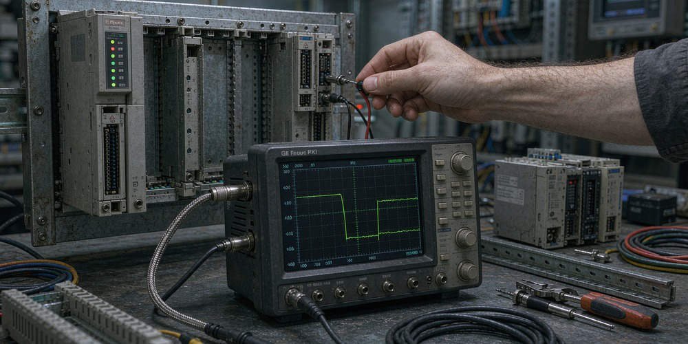
Power quality issues represent the primary trigger for spontaneous PLC reboots. Although power supply units work reliably at installation, internal capacitors degrade gradually over time. Consequently, high-current switching events from nearby heavy motors create momentary voltage sags. These micro-second voltage dips bypass standard multimeters but trigger the CPU under-voltage protection circuit. Therefore, maintenance teams must capture real-time power waveforms using a high-speed oscilloscope before replacing hardware.

Evaluating Thermal Stress and Long-Term Cabinet Enclosure Conditions

Heat accumulation degrades delicate microelectronics inside programmable logic controllers. Enclosure filters clog with industrial dust after extended operation without regular maintenance. As a result, internal cabinet temperatures steadily climb beyond the recommended 60°C operating limit. Excess heat triggers thermal protection mechanisms inside the CPU processor. Moreover, long-term thermal expansion loosens backplane connectors, creating intermittent physical connection drops during peak operational shifts.

Investigating CPU Firmware Restrictions and Software Watchdog Events

Software anomalies frequently mimic hardware failures in modern control systems. According to industrial control industry surveys, over 30% of unexpected PLC restarts originate from software watchdog timeouts. Heavy non-volatile memory write operations or unhandled system interrupts lock up the execution thread. Consequently, the internal watchdog timer resets the CPU to prevent erratic machine behavior. Engineers must analyze the PAC Machine Edition fault table before clearing CPU error logs.

Step-by-Step Diagnostic Sequence for Resolving CPE305 Reboots

  1. Preserve Diagnostic Error Tables: Connect to the CPU via PAC Machine Edition immediately and export the complete controller fault log.
  2. Monitor DC Power Quality: Install a transient power recorder to log 24V DC bus stability during heavy motor startup sequences.
  3. Inspect Physical Connections: Check backplane connectors, terminal blocks, and Energy Pack module cables for corrosion or mechanical looseness.
  4. Verify Cabinet Thermal Profile: Measure internal panel temperatures using thermal imaging cameras under full operational loads.

Inspecting Energy Pack Performance and Power Loss Backup Systems

The IC695CPE305 processor utilizes an Energy Pack capacitor module to preserve volatile RAM data during power outages. However, aging Energy Pack units can develop internal short circuits or fail to maintain adequate charge holding capacity. When an unstable Energy Pack draws excessive current from the CPU internal rail, it induces voltage drops across the processor board. Therefore, field technicians should regularly test and replace aging backup energy modules according to manufacturer maintenance schedules.

B2B Procurement Strategies and Backward Compatibility Verification

Replacing an IC695CPE305 module requires careful compatibility evaluation rather than quick component swapping. System integrators must verify CPU hardware revisions, installed firmware builds, and backplane bus speeds. While modern Emerson RX3i controllers support legacy Series 90-30 I/O modules, firmware mismatches can cause backplane communication errors. Procurement managers must review technical specifications thoroughly before scheduling system upgrades during maintenance windows.

Application Scenario: Chemical Plant Processing Line Recovery

A continuous chemical processing plant experienced random IC695CPE305 reboots every few days, interrupting critical batch mixing operations. The maintenance team initially suspected a defective CPU board and replaced the hardware, yet the reboots persisted. Powergear X Automation specialists audited the panel installation and discovered that aging panel cooling fans had failed, causing internal enclosure temperatures to reach 68°C.

The engineering team installed new cabinet ventilation fans and cleaned the clogged dust filters. Additionally, they updated the CPU firmware to the latest revision and adjusted the power supply monitoring parameters. These targeted actions reduced panel temperatures to a stable 38°C, completely eliminating random CPU reboots and restoring 100% processing line uptime.

To source reliable GE Fanuc PACSystems RX3i components and receive expert technical troubleshooting support, visit Powergear X Automation today for your factory automation needs.

Frequently Asked Questions (FAQ)

Q1: Should I immediately replace my IC695CPE305 CPU when random reboots start?
No. You should first investigate external power supply dips, cabinet overheating, and backplane looseness. Replacing the CPU will not resolve external electrical or thermal issues.

Q2: How does the Energy Pack affect CPU boot behavior on the PACSystems RX3i?
The Energy Pack powers the CPU memory save process during shutdown. A degraded or shorted Energy Pack can cause startup faults or force the CPU into reboot loops.

Q3: What tools are required to capture voltage transients causing PLC reboots?
Standard multimeters are too slow to detect millisecond voltage sags. You need a digital storage oscilloscope or a specialized power quality analyzer to capture brief DC power dips.

IC695CPK330 OPC UA Connection Limits & Edge Guide | Powergear X

Resolving OPC UA Connection Limits on IC695CPK330 Communicating with Edge Devices

Modern factory automation relies heavily on seamlessly connecting industrial controllers with cloud analytics and edge computing layers. The Emerson GE Fanuc PACSystems RX3i IC695CPK330 CPU integrates embedded Ethernet and an OPC UA server for direct data publishing. However, field engineers frequently encounter session bottlenecks when connecting multiple external edge devices. Powergear X Automation provides this engineering guide to clarify the root causes of OPC UA session limits and optimize system architecture for maximum performance.

Understanding Embedded OPC UA Architecture in Industrial Automation Systems

The IC695CPK330 controller operates as a core processing engine within distributed control systems (DCS) and programmable logic controller (PLC) networks. According to recent industrial IoT benchmark reports, over 65% of smart manufacturing deployments utilize OPC UA for secure edge communication. Emerson equips this CPU with embedded OPC UA server functionality to eliminate the need for costly external hardware gateways. However, engineers must recognize that PLC processing resources serve real-time control logic first, which restricts protocol session capacity.

Analyzing Hard Hardware Session Limits and Subscriptions Allocation

Engineers often confuse physical network connections with logical OPC UA sessions and subscriptions. Emerson technical documentation specifies that the IC695CPK330 OPC UA server supports a maximum of 5 concurrent sessions. Moreover, the server caps concurrent variable subscriptions at 10 and monitored items at 12,500 across all active sessions. Therefore, connecting six independent edge devices directly to the PLC causes immediate connection rejections, regardless of network bandwidth.

Distinguishing Firmware Protocols Constraints from CPU Processing Speed

Upgrading to a faster CPU does not automatically expand the embedded OPC UA session capacity. The 5-session boundary stems from firmware memory allocation rather than raw processing clock speed. Furthermore, aggressive client reconnection loops can leave stale sessions open on the server, artificially consuming resource slots. As a result, troubleshooting connection failures requires analyzing session lifecycles rather than replacing functional control system hardware.

Step-by-Step Optimization Sequence for Edge Data Aggregation

  1. Audit Existing Sessions: Utilize PAC Machine Edition diagnostics to monitor active OPC UA sessions and identify unclosed client connections.
  2. Implement Data Aggregation: Deploy a central OPC UA gateway server to consolidate data requests from multiple edge devices into a single session.
  3. Optimize Subscription Parameters: Group monitored variables into fewer subscriptions to reduce server memory overhead.
  4. Configure Reconnect Backoffs: Adjust client reconnect intervals to prevent rapid retry loops during temporary network dropouts.

Field Cybersecurity Configurations and Firmware Compatibility Standards

Robust security configurations are essential when exposing PLC data to external edge networks. The IC695CPK330 supports X.509 security certificates and encrypted communication profiles under IEC 62443 standards. Engineers must align security policies between the OPC UA server and client devices to prevent handshake failures. In addition, verifying firmware compatibility between the CPU and PAC Machine Edition ensures smooth certificate management and session stability.

B2B Sourcing Strategy and System Scaling Considerations

System integrators must evaluate communication requirements during the initial design phase of factory automation projects. If an enterprise architecture requires direct connections from dozens of edge devices, relying solely on embedded controller servers creates severe bottlenecks. Investing in dedicated communication modules or industrial edge gateways protects PLC core execution. Furthermore, procurement teams should consult automation specialists to select hardware that balances control performance with data scalability.

Application Scenario: Pharmaceutical Manufacturing Edge Integration

A major pharmaceutical plant utilized a PACSystems RX3i IC695CPK330 CPU to control a critical batch processing line. The engineering team attempted to connect seven independent applications, including SCADA, historian, energy monitor, and four edge analytics nodes, directly to the PLC via OPC UA. Consequently, two edge devices continuously failed to connect due to the 5-session limit.

To resolve the constraint, the team deployed a centralized OPC UA aggregation server. The central server established a single, secure session with the IC695CPK330 CPU to collect all 4,200 required data tags. The aggregator then distributed the data to all seven downstream edge applications simultaneously. This architectural shift reduced the PLC session load to 20% of capacity while ensuring real-time data access across the plant.

For high-performance PACSystems RX3i controllers, communication modules, and expert technical support, visit Powergear X Automation to upgrade your industrial control infrastructure.

Frequently Asked Questions (FAQ)

Q1: Can I increase the IC695CPK330 OPC UA session limit by upgrading the CPU firmware?
Firmware updates improve security and protocol stability but do not increase the fundamental 5-session limit. Expanding session capacity requires using an external OPC UA aggregation server or dedicated communication hardware.

Q2: What happens if an edge device disconnects abruptly without closing its OPC UA session?
The server holds the session open until the session timeout period expires. During this window, the stale session consumes one of the 5 available resource slots, potentially blocking new client connections.

Q3: Is it better to use multiple subscriptions or a single subscription for monitored variables?
Using a single grouped subscription is far more efficient. It minimizes server memory allocation and reduces communication overhead compared to creating multiple separate subscriptions across sessions.

GE Fanuc IC695ALG412 Thermocouple Module & Hold State Guide

Clarifying the GE Fanuc IC695ALG412 Thermocouple Input Module and Hold Last State Configurations

In industrial automation systems, engineers often confuse input data behavior with analog output module control settings. The GE Fanuc Emerson PACSystems RX3i IC695ALG412 is a 12-channel isolated thermocouple input module, not an analog output module. Consequently, engineers cannot configure it to hold 4-20mA or 0-10V control signals during CPU STOP mode. Powergear X Automation provides this guide to clarify the precise function of the IC695ALG412 module and prevent costly system misconfigurations.

Core Value of Precision Temperature Data Acquisition in Control Systems

The IC695ALG412 module provides high-accuracy temperature measurements for process control applications across chemical processing, power plants, and thermal treatment facilities. According to recent industrial sensor market reports, thermocouple sensors account for over 35% of temperature monitoring loops in heavy manufacturing. The IC695ALG412 processes millivolt signals from J, K, T, E, R, S, B, N, and C thermocouples. Channel-to-channel isolation prevents ground potential differences from distorting critical process metrics.

Distinguishing Thermocouple Input Data Hold from Analog Output Hold

Engineers must carefully distinguish input module data handling from field actuator signal retention. The IC695ALG412 supports a per-channel “Hold Last State” or “Default to 0” setting for incoming process values. However, this parameter only affects the memory registers that the PLC program reads during fault conditions. It does not send active analog signals to field equipment like control valves or variable frequency drives. Therefore, applications requiring physical signal retention during CPU STOP mode must use dedicated analog output modules like the IC695ALG704 or IC695ALG808.

Process Safety Risks Associated with Stale Temperature Values

Relying on frozen input values during sensor open-circuit faults introduces severe risks to factory automation systems. Configurable channel update rates on the IC695ALG412 range from 15ms to 120ms depending on digital filter selection. When a thermocouple breaks or disconnects, holding the last valid value masks dangerous temperature spikes in thermal reactors. As a result, control logic might fail to trigger emergency shutdown procedures. Maintenance teams must combine hardware diagnostic bits with PLC software alarm routines to detect open circuits immediately.

Field Installation and Terminal Block Verification Guidelines

Proper physical installation ensures long-term measurement stability in high-noise DCS environments. Maintenance personnel should install the IC695ALG412 into an RX3i Universal Backplane using approved terminal blocks. Compatible terminal units include the IC694TBB032, IC694TBB132, IC694TBS032, and IC694TBS132. Furthermore, technicians must route thermocouple extension wires away from heavy motor leads to avoid electromagnetic interference. Always verify physical module catalog numbers against control cabinet schematics during system retrofits.

B2B Procurement and Correct Analog Output Module Selection

System integrators must verify hardware specifications before purchasing replacement parts for legacy GE Fanuc or modern Emerson RX3i racks. If your application specification demands “Hold Last State on CPU STOP” for field actuators, select appropriate analog output modules instead. Modules such as the IC695ALG704, IC695ALG708, and IC695ALG808 feature configurable Output Default parameters specifically designed for output signal hold. Procurement managers should cross-reference hardware revision numbers to guarantee backplane compatibility before scheduled downtime.

Application Scenario: Thermal Processing Furnace Control Strategy

A steel heat-treatment plant experienced unexpected temperature fluctuations after a hardware upgrade. Technicians mistakenly assumed the IC695ALG412 input module controlled the furnace gas valve directly. Consequently, they enabled the input “Hold Last State” parameter, expecting the valve to maintain its position during CPU maintenance.

To correct the control strategy, the engineering team separated the input and output functions cleanly. They configured the IC695ALG412 to generate an immediate “Open Circuit” diagnostic fault upon sensor failure. Additionally, they installed an IC695ALG704 analog output module to drive the gas valve positioner, setting its Output Default property to “Hold Last State.” This dual-layer architecture ensured precise temperature feedback while maintaining safe actuator control during CPU disruptions.

For authentic GE Fanuc and Emerson PACSystems RX3i modules, technical documentation, and expert sourcing, visit Powergear X Automation to support your industrial infrastructure.

Frequently Asked Questions (FAQ)

Q1: Can the IC695ALG412 module maintain a 4-20mA output signal when the CPU enters STOP mode?
No. The IC695ALG412 is strictly an input module for thermocouples and voltage signals. You must use an analog output module like the IC695ALG704 or IC695ALG808 to hold analog output signals during CPU STOP mode.

Q2: What happens when a thermocouple disconnects from an IC695ALG412 channel?
Depending on your Proficy Machine Edition configuration, the channel will either report a “Default to 0” value or “Hold Last State.” The module also sets an open-circuit diagnostic bit in the PLC status table.

Q3: Which terminal blocks are compatible with the IC695ALG412 thermocouple module?
The IC695ALG412 connects to standard RX3i terminal blocks, including IC694TBB032, IC694TBB132, IC694TBS032, and IC694TBS132 spring or box-clamp versions.

GE Fanuc IC695PSA040 vs PSA140 Power Redundancy Guide

Debunking Power Redundancy Myths: GE Fanuc IC695PSA040 vs IC695PSA140 in PACSystems RX3i PLCs

In industrial automation, power supply reliability directly impacts continuous factory operations. A common field misconception suggests that installing two GE Fanuc IC695PSA040 modules creates a redundant power system. However, official Emerson Automation Solutions documentation explicitly forbids running dual IC695PSA040 modules on a single RX3i Universal Backplane. Powergear X Automation provides this engineering analysis to clarify power architecture rules and prevent costly hardware damage in factory automation environments.

Understanding the Power Architecture of GE Fanuc PACSystems RX3i

The IC695PSA040 serves as a standard 40-Watt AC power supply module. It delivers internal DC power voltages including 5.1VDC, 3.3VDC, and 24VDC relay outputs. However, Emerson specifies that this model lacks active load sharing circuitry. Installing two non-sharing power units onto the same backplane creates internal voltage imbalances. Consequently, current will not split evenly between modules, which risks backplane damage and system trips.

Comparing IC695PSA040 Standard Modules with IC695PSA140 Multipurpose Units

Achieving true power redundancy requires specialized multipurpose hardware. The IC695PSA140 and IC695PSD140 multipurpose power supplies feature internal load-sharing diodes. Industrial reliability reports indicate that properly configured N+1 power redundancy reduces unexpected PLC shutdowns by up to 40%. Therefore, control engineers must deploy PSA140 modules when designing high-availability DCS or PLC architectures.

Key Differences Between Standard and Multipurpose RX3i Power Supplies

  • IC695PSA040 Standard Module: Provides 40W output, supports single-slot installation only, lacks load sharing, and forbids dual-module backplane configurations.
  • IC695PSA140 Multipurpose Module: Provides 40W output, supports load-sharing modes, enables 1+1 hardware redundancy, and allows multiple units on one backplane.
  • System Mixing Restrictions: Prohibits combining PSA040 standard modules with PSA140 multipurpose modules in any backplane configuration.

Field Inspection Protocols and Firmware Revision Risks

  1. Verify Module Part Numbers: Read the physical faceplate label to confirm if the unit is a PSA040 or PSA140.
  2. Check Hardware Revision Levels: Identify legacy revisions like IC695PSA040C, which present severe damage risks if paralleled.
  3. Calculate Total Backplane Load: Utilize Proficy Machine Edition software to verify total current draw across all I/O modules.
  4. Enforce Single Module Limits: Ensure only one PSA040 resides on the backplane during single-power supply deployments.

Best Practices for Control Cabinet Engineering and Procurement

Procurement managers should avoid purchasing duplicate PSA040 units to solve capacity shortages. Adding a second standard power supply fails to increase overall system wattage. Instead, engineers must calculate total system consumption within Proficy Machine Edition software first. Moreover, migrating from standard to multipurpose power units requires updating backplane configuration files before commissioning.

Application Scenario: Chemical Plant Power System Upgrade

A continuous chemical processing facility experienced intermittent PLC resets on a critical process unit. Inspection revealed two IC695PSA040 modules installed on a single IC695 Universal Backplane under the false assumption of 1+1 redundancy. The non-sharing circuitry caused one power supply to overheat while attempting to carry the entire electrical load.

To resolve the issue, the engineering team removed both standard units and reconfigured the backplane. They installed two IC695PSA140 multipurpose power supplies and updated the hardware configuration settings. This adjustment established true 1+1 active load sharing, eliminating thermal stress and restoring continuous operational stability to the facility.

For authentic GE Fanuc hardware, expert procurement advice, and high-performance PLC components, visit Powergear X Automation to upgrade your critical control infrastructure.

Frequently Asked Questions (FAQ)

Q1: Can I install two IC695PSA040 modules on one RX3i backplane to double output power to 80W?
No. The IC695PSA040 does not support load sharing or parallel operation. Adding a second module will not double capacity and can damage the backplane or power modules.

Q2: Can I mix an IC695PSA040 with an IC695PSA140 on the same backplane?
No. Emerson guidelines strictly prohibit mixing standard power supplies with multipurpose power supplies. Mixing these modules destabilizes internal backplane voltage rails.

Q3: What happens if an older IC695PSA040 revision C module is wired in parallel with another power supply?
Legacy hardware revisions like revision C lack protective isolators for dual operation. Paralleling these units creates thermal overload risks and can permanently destroy backplane traces.

IC695EIS001 Technical Analysis | Powergear X Automation

Clarifying GE PACSystems RX3i IC695EIS001: Ethernet IEC 60870-5-104 Server Module Technical Guide

In industrial automation, correct component identification prevents costly architectural errors in control systems. A common misconception misidentifies the GE Fanuc PACSystems RX3i IC695EIS001 as an isolated discrete input module. However, technical documentation confirms that the IC695EIS001 serves as an Ethernet IEC 60870-5-104 Server Module. Powergear X Automation presents this guide to clarify its actual function, technical boundary, and isolation specifications for factory automation systems.

Understanding the Core Value of IEC 60870-5-104 Protocol Integration

The IC695EIS001 module enables high-speed IEC 60870-5-104 telecontrol protocol communication over Ethernet networks. Power utilities, substations, and water management facilities rely heavily on this standardized protocol for SCADA data exchange. Consequently, the module operates purely within the network communication layer of the RX3i PLC platform. System integrators must not treat this module as a field-level discrete input interface for 24VDC or 230VAC field signals.

Dispelling Misconceptions Regarding Channel Isolation Voltage Ratings

Engineers often search for channel-to-channel isolation specs like 250 VAC or 1500 VAC for the IC695EIS001. However, these voltage ratings belong exclusively to specialized discrete and analog I/O modules. The IC695EIS001 lacks field input terminals, so it provides no channel isolation rating for field wiring. Therefore, procurement teams must verify technical datasheets before attempting to replace isolated I/O hardware with communication modules.

Differentiating Between Isolation Withstand and Surge Protection Limitations

Many plant operators mistakenly assume that I/O isolation guarantees total protection against high-voltage AC cross-connections. Standard isolation barriers withstand temporary dielectric testing up to 1500 VAC for one minute. Nevertheless, sustained 230 VAC surges or direct lightning strikes easily exceed these safety limits. As a result, field equipment requires external surge suppression devices rather than relying solely on internal module isolation.

Key Step-by-Step Isolation Verification and Commissioning Sequence

  1. Identify Signal Layer Types: Separate networking modules like the IC695EIS001 from physical discrete input modules during initial cabinet layout design.
  2. Audit Field Input Voltages: Match field sensor voltages directly with dedicated RX3i Discrete Input Module specifications.
  3. Implement Physical Segregation: Route 230VAC power cables away from 24VDC signal lines and Ethernet communication runs inside wireways.
  4. Install External Circuit Protection: Place fast-acting fuses and surge suppressors on field terminal blocks to protect PLC backplanes.

Best Practices for Cabinet Wiring and High-Voltage Segregation

Electrical noise and accidental high-voltage cross-connections remain major causes of PLC backplane damage in DCS environments. Industry standards like IEC 61000 mandate strict physical separation between high-power circuits and low-voltage control lines. Moreover, maintenance teams must install properly grounded shielded twisted-pair cables for all Ethernet links. Implementing these physical isolation measures prevents inductive coupling and extends hardware lifespan across process control applications.

B2B Procurement Strategies for PACSystems RX3i Components

Purchasing agents must verify exact module catalog numbers to avoid erroneous component replacements. While vendors may list the IC695EIS001 under generic input categories, technical buyers must confirm its communication profile. Choosing the correct communication or I/O module ensures seamless integration with existing PACSystems RX3i backplanes. Furthermore, buyers should maintain version control documentation to simplify future emergency replacements.

Application Scenario: Power Substation SCADA Gateway Upgrade

A regional power utility needed to integrate an existing PACSystems RX3i controller into a modern regional SCADA network. The engineering team installed an IC695EIS001 module to establish an Ethernet IEC 60870-5-104 server interface. Concurrently, they routed field alarm contacts to dedicated isolated discrete input cards protected by terminal block fuses.

This architectural separation isolated network data traffic from field electrical noise completely. The SCADA center achieved real-time data telemetry within 50 milliseconds over Ethernet. Meanwhile, external fuses successfully cleared a 230VAC field wiring fault without damaging the RX3i CPU rack or communication interfaces.

To source authentic PACSystems RX3i modules and optimize your industrial control infrastructure, visit Powergear X Automation for expert technical solutions and reliable hardware fulfillment.

Frequently Asked Questions (FAQ)

Q1: What is the channel isolation voltage for the IC695EIS001 module?
This specification is not applicable. The IC695EIS001 is an Ethernet IEC 60870-5-104 Server Module rather than a discrete input module, so it has no field channel isolation rating.

Q2: Can the IC695EIS001 protect my RX3i CPU rack against accidental 230VAC field cross-connections?
No. The module operates strictly as a network interface and does not connect to field input devices. Protecting the CPU rack requires correct isolated DI modules, fuses, and proper wiring practices.

Q3: Which module should I select for 24VDC or 120VAC field signal inputs on an RX3i system?
You should select a dedicated RX3i Discrete Input Module (such as an IC695MDL or IC694MDL series input card) designed specifically for field voltage levels.

Fix PACSystems RX3i IC695CRU320 Dual CPU Failover & Sync Issues

Troubleshooting PACSystems RX3i IC695CRU320 Dual Redundancy CPU Failover Issues

In high-availability industrial automation environments, continuous runtime remains non-negotiable. Dual-redundant Programmable Logic Controller (PLC) configurations protect continuous process facilities from unplanned downtime. The Emerson GE Fanuc PACSystems RX3i IC695CRU320 CPU delivers high-speed CPU redundancy across critical process applications. However, plant engineers sometimes report that a secondary CPU fails to take control when the primary CPU faults, even with dual optical fiber links intact. Powergear X Automation provides this troubleshooting guide to resolve failover delays and synchronization errors in IC695CRU320 systems.

Physical Fiber Integrity Does Not Equal CPU Synchronization

A common misconception in factory automation involves confusing physical link status with application synchronization. The IC695CRU320 CPU relies on IC695RMX128 or IC695RMX228 Redundancy Memory Xchange modules to mirror controller memory. Dual fiber optic lines provide link redundancy, but healthy fiber optical LEDs only confirm physical layer continuity. If the backup CPU encounters hardware mismatches or fatal faults, it refuses to enter the Synchronized Backup state. Consequently, the primary CPU failure triggers an unrecoverable system shutdown instead of a seamless failover.

Understanding the Fail Wait Time Parameter in Redundant Systems

PACSystems RX3i hot standby architectures utilize discrete synchronization points within each scan cycle. The default Fail Wait Time setting operates at 60 milliseconds, adjustable from 40 to 400 milliseconds. If the active CPU fails to reach a synchronization checkpoint within this window, the secondary unit initiates takeover protocols. However, the backup CPU must maintain full synchronization prior to the event. According to industrial automation reliability reports, over 70% of redundant failover errors stem from pre-existing synchronization loss rather than physical link disruption.

Hardware Revision and Firmware Compatibility Requirements

Deploying a high-availability DCS or PLC architecture requires identical CPU and hardware revisions. Primary and secondary RX3i racks must run identical firmware versions and match memory configurations. For example, mixing an older IC695CRU320 CPU revision with a newer hardware module causes parameter rejection during runtime synchronization. Furthermore, engineers must verify that both controllers reside on compatible RX3i Universal Backplanes (IC695CHS012 or IC695CHS016) rather than legacy Series 90-30 expansion racks.

Step-by-Step Diagnostic Sequence for Secondary CPU Failover

  1. Inspect the Redundancy Fault Table: Connect via Proficy Machine Edition (PME) and examine Controller Fault Group 138 to identify specific synchronization errors.
  2. Verify RMX Module Diagnostics: Check the OK, OWN, DATA, and SIGNAL DETECT LEDs on both IC695RMX128 modules to confirm internal memory transfers.
  3. Validate Synchronized Status: Confirm that the PME software status bar explicitly reports “Synchronized Backup” for the secondary controller.
  4. Audit PME Project Hardware Configuration: Verify that the Transfer List, Redundancy Mode, and Primary/Secondary settings match across both CPU projects.

Proactive Maintenance Practices for Industrial Control Systems

Preventive maintenance minimizes unexpected failover disruptions in continuous process plants. Maintenance teams should routinely archive CPU diagnostic logs and back up active PME projects. When replacing a damaged IC695CRU320 module, engineers should verify firmware parity before inserting the card into a live backplane. Additionally, system integrators must schedule periodic failover tests during planned maintenance windows to validate seamless takeover under load.

B2B Sourcing and Legacy Replacement Strategies

Procuring replacement parts for legacy GE Fanuc or modern Emerson PACSystems RX3i platforms requires thorough verification. B2B buyers should avoid sourcing replacement CPUs based solely on the core part number. Requesting firmware documentation, hardware revision levels, and battery test records ensures immediate drop-in compatibility. Purchasing verified hardware prevents configuration mismatches and protects critical automation infrastructure from extended downtime.

Application Scenario: Petrochemical Distillation Unit Recovery

A continuous chemical refinery experienced an unprogrammed plant shutdown when the primary IC695CRU320 CPU suffered a power supply trip. Although dual fiber cables connected the RMX228 modules, the backup CPU failed to assume control. The engineering team connected PME software and discovered Fault Group 138 error codes indicating an unsynchronized memory transfer list. A previous maintenance update modified the primary CPU variable transfer list without updating the secondary project file.

The team re-aligned the PME project configurations, re-downloaded the matching hardware settings, and re-established the “Synchronized Backup” state across both racks. During a subsequent planned simulation, disconnecting the primary CPU power triggered an immediate, bumpless transfer to the backup unit within 30 milliseconds, maintaining uninterrupted valve control across the refinery process.

To optimize your control system uptime with genuine PLC components and expert technical support, visit Powergear X Automation to explore our inventory of PACSystems RX3i solutions.

Frequently Asked Questions (FAQ)

Q1: Why does the secondary IC695CRU320 CPU show RUN mode but fail to take over during an active CPU fault?
RUN mode only indicates that the CPU is executing logic. The secondary unit must explicitly reach the “Synchronized Backup” state to take control; otherwise, it lacks the real-time process data necessary to manage outputs safely.

Q2: Can I pair an IC695CRU320 CPU with a different RX3i CPU model like the CPE330?
No. Hot standby redundancy requires identical or strictly qualified compatible CPU architectures. Mixing different CPU families prevents memory synchronization and breaks redundancy logic.

Q3: What indicates that an IC695RMX128 redundancy module requires replacement?
If the RMX module OK LED remains unlit or indicates an internal hardware failure after a rack power cycle, the module cannot exchange memory data and must be replaced to restore redundancy.

Genius Network Interface IC200GBI001 for Legacy PLC Support

Genius Network Interface IC200GBI001 for Legacy PLC Support

Maximize Legacy System Lifespan with the IC200GBI001 Genius Interface

The IC200GBI001 Genius Network Interface serves as a vital bridge between modern VersaMax I/O and legacy GE control architectures. It specifically solves a major headache in brownfield industrial automation projects. Engineers often struggle to maintain aging systems without committing to a full PLC replacement. This module allows plants to protect their existing investments while adding flexible I/O capabilities.

Genius Network Interface IC200GBI001 for Legacy PLC Support

Seamless Integration with GE Series 90-30 Systems

The IC200GBI001 natively supports the Genius protocol, the backbone of legacy GE 90-30 PLCs. It communicates directly with Genius Bus Controllers, such as the IC693BEM331. This compatibility ensures that your existing control systems remain functional during phased hardware upgrades. Consequently, you can modernize remote I/O hardware while the central CPU stays unchanged.

Deterministic Performance in Factory Automation

Unlike some modern Ethernet protocols, Genius operates as a deterministic, token-passing network. While it lacks the raw speed of Gigabit Ethernet, its scan behavior remains highly predictable. In my experience at Powergear X Automation, network latency rarely hinders performance. The PLC scan cycle typically limits response time, not the interface itself. Therefore, it remains ideal for discrete control and critical process interlocking.

Superior Noise Immunity for Harsh Environments

Industrial settings often suffer from high electromagnetic interference (EMI) from large motors and welders. The IC200GBI001 excels here because the Genius network offers better stability than many early Ethernet implementations. This robust design reduces intermittent I/O faults and maximizes system uptime. It aligns perfectly with IEC standards for factory automation in high-noise zones.

Best Practices for Installation and Grounding

Success with the IC200GBI001 requires precise configuration and physical installation. You must assign a unique Genius Device Number to avoid “I/O not present” alarms. Furthermore, proper grounding is the most critical factor for communication stability. Always ground the cable shield at a single point, usually the PLC side. This prevents ground loops that often plague long cable runs across the plant floor.

  • Verify unique Genius Device addresses before powering up.
  • Use high-quality shielded twisted-pair cabling for all runs.
  • Ground the shield only at the Bus Controller.
  • Maintain a minimum distance from high-voltage power lines.
  • Keep a pre-configured spare module for emergency recovery.

Strategic Insights from Powergear X Automation

At Powergear X Automation, we view the IC200GBI001 as a strategic lifecycle tool. While the industry moves toward Industrial Ethernet, many facilities cannot afford the downtime of a complete migration. This module provides a reliable “middle ground.” It allows for incremental modernization without the risk of a massive system overhaul. However, always plan your long-term migration path while using these legacy-friendly tools.

Application Scenarios

  • Phased Upgrades: Replacing failing legacy I/O blocks with VersaMax modules while keeping the 90-30 CPU.
  • Remote Expansion: Adding new sensors to an existing Genius network without installing new PLC racks.
  • High-EMI Zones: Deploying I/O in areas where standard unshielded Ethernet might fail due to electrical noise.

Expert FAQ

How do I choose between repairing old Genius blocks or buying the IC200GBI001?
Repairing old blocks often leads to recurring failures. The IC200GBI001 is a better investment because it utilizes modern VersaMax hardware. This transition improves reliability and simplifies future part sourcing.

What is the most common mistake during commissioning?
Most engineers forget to check the baud rate. The IC200GBI001 must match the existing network speed (38.4Kbps, 76.8Kbps, or 153.6Kbps). A mismatch will prevent the entire bus from communicating.

Can I use this module to bridge to a third-party PLC?
Directly, no. It requires a Genius Bus Controller. However, if your third-party system has a Genius gateway, communication is possible. Always verify the physical layer compatibility first.

For more technical support and high-quality automation components, visit Powergear X Automation to find the right solution for your facility.

GE Fanuc IC200MDL740 A Guide to PLC Module Decoding

GE Fanuc IC200MDL740: A Guide to PLC Module Decoding

Decoding GE Fanuc PLC Model Numbers: How to Identify Input and Output Modules

Navigating the complexities of industrial automation hardware requires precision. For engineers and procurement specialists working with GE Fanuc systems, the model number serves as a technical roadmap. Misidentifying a module can lead to catastrophic hardware failure or prolonged system downtime. This guide breaks down the nomenclature of the VersaMax series, using the IC200MDL740 as a primary case study.

GE Fanuc IC200MDL740 A Guide to PLC Module Decoding

The Anatomy of a GE Fanuc Model Number

Every character in a GE Fanuc model number represents a specific hardware attribute. Typically, the prefix “IC200” identifies the VersaMax family, which remains a staple in factory automation due to its modularity. The following three letters provide the functional classification. At Powergear X Automation, we emphasize that understanding these codes is the fastest way to verify signal flow during the design phase.

Differentiating MDL, MDO, and MDR Codes

The functional code is the most critical segment for distinguishing between signal directions.

  • MDL (Discrete Input): These modules receive signals from field devices like limit switches or proximity sensors.
  • MDO (Discrete Output): These modules drive loads using solid-state transistors, commonly found in high-speed switching tasks.
  • MDR (Relay Output): These utilize mechanical relays to switch higher currents or AC/DC loads.

Therefore, an IC200MDL740 is strictly an input module. Using it to power a solenoid valve will not work and may trigger a PLC fault.

Technical Specifications of the IC200MDL740

The numeric suffix “740” provides deeper insight into the electrical characteristics. Specifically, the IC200MDL740 features 16 points of 24 VDC positive logic (sinking) inputs. These modules incorporate optical isolation to protect the internal logic from external voltage spikes. In control systems for oil and gas, this isolation prevents electrical noise from corrupting data integrity.

Field Experience: Practical Installation Tips

From my 15 years in the field at Powergear X Automation, I have observed that most commissioning errors stem from simple wiring oversights.

  • Labeling Integrity: Always label wires according to the MDL/MDO distinction before power-up.
  • Voltage Matching: Ensure the field power supply matches the 24 VDC requirement of the 740 series.
  • Vibration Management: Use high-quality ferrules in environments with heavy machinery to prevent “ghost signals.”
  • Noise Suppression: Implement external shielding for long cable runs to maintain signal clarity.

The Evolution of I/O in Modern Automation

While GE Fanuc transitioned through various brand iterations (GE IP, Emerson), the core logic of these model numbers remains consistent. Modern DCS and PLC environments still rely on these standardized naming conventions for legacy support. Our team at Powergear X Automation recommends keeping a digital cross-reference sheet to expedite spare parts procurement and emergency repairs.

Expert FAQ: Selection and Maintenance

Q1: Can I replace an MDL input module with an MDR relay module if the voltages match?
No, they serve opposite functions. An MDL receives information, while an MDR sends commands. Swapping them will result in a non-functional loop and potential short circuits.

Q2: What is the most common failure point for the IC200MDL740 in harsh environments?
Over-voltage on the input pins is the leading cause. While they are opto-isolated, a sustained surge from a faulty sensor can eventually degrade the internal circuitry.

Q3: How do I verify if a module is “Sourcing” or “Sinking” without a manual?
Generally, GE Fanuc MDL modules are grouped by logic type. The 740 is a “Sinking” input, meaning it requires a “Sourcing” sensor. Always check the wiring diagram on the side of the module housing for the common (COM) terminal polarity.

Application Scenarios

  • Manufacturing: Using MDL740 modules to monitor conveyor belt status via photoelectric eyes.
  • Chemical Processing: Integrating MDO output modules to trigger safety alarms based on input thresholds.
  • Water Treatment: Utilizing MDR modules for heavy-duty motor starter coils that require high-current switching.

For more technical insights and a comprehensive inventory of GE Fanuc components, visit the experts at Powergear X Automation. We provide the technical support and hardware reliability your facility demands.

Maximizing Uptime: Why GE RX3i Excels in Continuous Production

RX7i to RX3i Migration Guide | Optimize Industrial Control

Maximizing Industrial Efficiency: Migrating from RX7i to PACSystems RX3i

The Strategic Value of System Modernization

Modernizing your control infrastructure from the legacy RX7i to the PACSystems RX3i platform represents a significant leap in operational capability. In my experience at Powergear X Automation, we see that this transition isn’t just about replacing hardware. It is about unlocking higher communication bandwidth and superior flexibility. Industries such as petrochemicals and pharmaceuticals require precise control. Consequently, the RX3i provides the necessary backbone for complex logic and high-speed data acquisition.

Maximizing Uptime: Why GE RX3i Excels in Continuous Production

Technical Deep Dive: Processing Power and Memory

The heart of the RX3i upgrade lies in its advanced CPU modules, such as the IC698CPE020, CPE030, and CPE040. These processors utilize Pentium M technology to deliver significantly faster clock speeds compared to their predecessors.

  • Reduced Cycle Times: Higher clock speeds shorten logic scan cycles.
  • Precision Control: Faster response improves temperature regulation in chemical reactors.
  • Waste Reduction: High-speed packaging lines benefit from decreased reject rates.

Moreover, the expanded cache memory ensures that the system handles large-scale automation tasks without latency.

Ensuring Continuity through Advanced Redundancy

For mission-critical environments, the IC698CRE020 redundancy module is indispensable. This hardware facilitates instantaneous synchronized switching between primary and backup controllers.

  • Zero Downtime: Automated failover prevents costly unplanned shutdowns.
  • Safety Compliance: The architecture aligns with rigorous IEC 61508 standards.
  • Risk Mitigation: Redundancy eliminates single points of failure in energy grids.

Our team often notes that high-reliability systems pay for themselves by avoiding just one hour of production stoppage.

Optimizing Connectivity and Protocol Integration

The IC698ETM001 Ethernet module serves as the bridge for modern industrial internet of things (IIoT) applications. It supports 100 Mbps throughput and integrates seamlessly with Modbus/TCP and GE Ethernet/IP protocols. Therefore, users experience significantly lower latency in SCADA systems. This improved connectivity allows for smoother remote diagnostics. As a result, engineers spend less time on-site during commissioning and troubleshooting phases.

Best Practices for Installation and Maintenance

To ensure long-term stability, technical teams must follow strict physical installation protocols. High-vibration environments demand specific mechanical reinforcements.

  • Use anti-vibration bolts to secure CPU modules.
  • Apply vibration-resistant ferrules on all wiring ports.
  • Install external surge protectors for Ethernet interfaces.
  • Maintain cabinet temperatures between 0°C and 60°C.
  • Clean air ducts and cooling fans quarterly.

Proper thermal management prevents premature component aging. Furthermore, shielding the CPU from power surges protects your capital investment from grid fluctuations.

Powergear X Automation Commentary

At Powergear X Automation, we believe the industry is shifting toward “Software-Defined Automation.” While the RX3i is robust hardware, its true strength lies in how it handles data-intensive workloads. We recommend that users do not just “swap” modules. Instead, use this migration to audit your network topology. Upgrading to RX3i offers a rare window to optimize your entire control loop for the next decade of production.

Practical Application Scenarios

  • Petrochemical Refining: Managing thousands of I/O points with high-speed redundancy for safety-instrumented functions.
  • Pharmaceutical Batching: Utilizing precise CPU scanning to meet strict FDA regulatory tracking and dosage accuracy.
  • Automotive Assembly: Integrating multiple third-party sensors via Ethernet/IP for real-time quality monitoring.

Frequently Asked Questions (FAQ)

1. When is the right time to move from RX7i to RX3i?
You should consider an upgrade if your current RX7i system experiences “logic lag” or if you cannot find spare parts easily. Additionally, if your facility requires better integration with modern SCADA or Cloud platforms, the RX3i is the logical successor.

2. Can I reuse my existing RX7i I/O racks with a new RX3i CPU?
The RX3i is designed for high backward compatibility. Most RX7i I/O modules work perfectly; however, very early ETM modules or specialized high-power units may require firmware updates. We suggest a full compatibility audit before purchasing.

3. What is the most common mistake during RX3i commissioning?
The most frequent error is neglecting the grounding and surge protection of the Ethernet ports. Unlike older serial connections, high-speed Ethernet is sensitive to electromagnetic interference. Always use industrial-grade shielded cables to ensure data integrity.

Looking for genuine GE PACSystems components or expert migration support? Visit the experts at Powergear X Automation to find the latest CPU modules and customized control solutions for your facility.

GE Fanuc RX3i Applications in Energy and Manufacturing

RX3i PLC: Powering Industrial Automation and Control Systems

The Versatile Powerhouse: GE Fanuc (Emerson) RX3i PLC in Modern Industrial Automation

The RX3i PLC is a flagship product. It was originally from GE Fanuc. Now it is part of Emerson’s suite. It is a critical asset in modern control. This platform is for demanding applications. It offers great reliability. It provides real-time processing. Its adoption is widespread. This confirms its preferred status.

Understanding the RX3i as a Programmable Automation Controller (PAC)

The RX3i is more than a PLC. It is a true PAC. It combines PLC ruggedness with advanced features. These include fast CPUs. It has deterministic Ethernet. It uses modular I/O. Its architecture is very scalable. It supports small machine control. It also runs large factory networks.

✅ Key Characteristics:

High-Speed Processing: It ensures minimal scan times.

Hot-Swap I/O: Replace modules without stopping.

Robust Communication: Supports PROFINET, Modbus, Serial.

System Integration: Handles safety and motion control.

Powering the Grid: Applications in the Energy and Utilities Sector

The energy industry needs robust control. Downtime is costly and hazardous. The RX3i manages key auxiliary functions.

It controls Balance of Plant in thermal plants. It manages boiler controls. And it handles cooling water systems. It aids substation automation. It controls wind and solar farms. Redundancy options are key here. Reliable systems cut unplanned outages.

From Wellhead to Refinery: Reliability in Oil and Gas Operations

The oil and gas sector uses the RX3i. It works in extreme environments.

Common applications include wellhead control. It manages pipeline compressor stations. It automates gas processing separation. And it integrates with SCADA systems. It works with certified safety systems. It manages remote I/O effectively.

Ensuring Public Health: Water and Wastewater Treatment Automation

Water facilities need stable control systems. Public safety depends on it. The RX3i is often chosen.

It controls raw water intake. It manages high-pressure pump stations. And it oversees aeration and sludge handling. Its longevity minimizes maintenance risks. It assures continuous, compliant operation.

Accelerating Production: High-Speed Discrete and Factory Automation

Manufacturing needs speed and synchronization. The RX3i enables higher throughput.

It is used in high-speed packaging. It controls complex assembly cells. And it integrates robotics smoothly. It connects with HMIs and VFDs. This creates adaptable production lines.

My Take: The Value Proposition of Emerson’s RX3i

The RX3i stays relevant for two reasons. It has backward compatibility. It is part of Emerson’s portfolio. This protects prior investment. It also allows for modernization.

It bridges field control and higher systems. These include DCS or MES layers. Engineers trust this workhorse. One platform serves many applications. This is its main advantage.

🔧 Technical Advantages in Implementation:

Simple configuration for redundant CPUs. It handles large tag databases well. It uses a standardized programming environment.

Seamless Data Exchange: Integration with SCADA and DCS Architectures

The RX3i is an intelligent I/O layer. It fits within larger supervisory architectures. It communicates with SCADA and DCS.

This allows reliable field-level control. It provides a stream of data. It supports standard industrial protocols. And it links legacy and modern equipment.

Conclusion: A Trusted Platform for Mission-Critical Control

The RX3i PLC is critically important. It combines high performance and rugged design. It has extensive communication capabilities. And t is a go-to solution for many industries. These include power generation and oil. It works in manufacturing and infrastructure. Its success proves its reliability.

FAQ: Expert Insights on RX3i Deployment

Q1: What is a common migration pitfall?

A common pitfall involves I/O configuration. The RX3i offers a migration path. Older programming was register-based. The new system is tag-based. This must be updated. Thorough testing is essential. This uses the new hardware’s full potential.

Q2: How does its PAC architecture help analytics?

The PAC architecture provides more power. It has greater memory capacity. This handles complex control logic. It manages direct, high-speed data connections. It can push data efficiently. This is great for real-time analytics. It aids predictive maintenance applications.

Q3: When should a smaller plant choose the RX3i?

Choose the RX3i for future scalability. Choose it for inherent redundancy. Use it for high-speed synchronization. Lighter-duty PLCs cannot guarantee this. It future-proofs your system. It provides better security features. And it simplifies later DCS or MES integration.

Explore Advanced Automation Solutions

Learn more about the RX3i PLC. See how it optimizes industrial processes. View specific application case studies. Please visit our website. Powergear X Automation provides expert solutions. We tailor them for complex environments.

Back to Top
Product has been added to your cart