Over 50,000 hot-selling automation module components.

Troubleshooting Bently Nevada 3300 XL Proximitor 0V Output

Bently Nevada 3300 XL 0V Output: Is It a Dead Proximitor or Lost -24VDC Power?

In the field of industrial automation, maintaining machinery protection systems is vital for operational uptime. During routine maintenance of a Bently Nevada 3500 Monitoring System, encountering a 0V output from a 3300 XL Proximitor Sensor is a common challenge. Many instrument technicians immediately assume that the proximity transducer is burnt out. However, practical field experience shows that a 0V reading does not automatically mean you have a dead sensor.

A zero-volt output on a Bently Nevada 3300 XL Proximitor sensor typically points to one of several underlying causes:

  • Complete loss of the required -24VDC power supply.
  • Reversed power polarity or a loose common (COM) connection.
  • A short circuit in the proximity probe or the extension cable.
  • Internal electronic component failure within the Proximitor itself.
  • An issue within the input card channels of the Bently Nevada 3500 rack.

In factory automation, power distribution issues often impact multiple channels simultaneously. In fact, a lost -24VDC supply rail is statistically more common than a single destroyed Proximitor module. Therefore, systematic signal loop troubleshooting is essential before you order costly replacement hardware.

For high-quality spare parts, system upgrades, and expert support on Bently Nevada and PLC/DCS modules, discover reliable solutions at Powergear X Automation to keep your operations running smoothly.

The Role of the 3300 XL Proximitor in Machinery Protection

The Bently Nevada 3300 XL Proximitor serves as a critical bridge in machinery protection systems. It converts high-frequency physical gaps measured by eddy current probes into proportional voltage signals. These signals represent vital machine metrics like axial displacement, shaft vibration, and keyphase speed on rotating equipment.

Heavy industries like oil and gas, chemical processing, power generation, and steel production rely on these continuous measurements. This raw data allows the Bently Nevada 3500 rack to trigger alarms or emergency machine trips. Consequently, any signal failure can lead to catastrophic machine damage or unexpected plant shutdowns.

Crucially, the Proximitor does not operate in isolation. It forms a complete tuned resonant circuit with a specific 3300 XL probe and extension cable. Understanding this interconnection is key to diagnosing a 0V output condition.

Analyzing the -24VDC Power Supply Requirement

The 3300 XL Proximitor requires a stable, low-noise -24VDC supply to power its internal oscillator and demodulator circuitry. This negative voltage power scheme is standard across Bently Nevada hardware but differs from typical 24VDC industrial control systems.

When multiple sensors are grouped in a single field junction box, they often share a common power distribution block. Therefore, a failing or shorted -24VDC power module can take down an entire group of sensors. In this scenario, checking the central power source saves hours of individual sensor testing.

To verify the power state, always measure the voltage directly at the Proximitor’s power terminals. Ensure your multimeter shows a clean -24VDC relative to the common terminal, with minimal electrical noise or voltage ripple.

Why a Constant 0V Represents a Loop Failure

A standard 8mm 3300 XL proximity system operates over a dynamic range of -2VDC to -18VDC. When properly gapped and calibrated, the nominal DC bias voltage (or gap voltage) sits around -10VDC. Superimposed on this DC bias is the AC voltage representing high-frequency shaft vibration.

Because the active operating range is strictly negative, a constant 0V output is an out-of-limits state. It indicates that the Proximitor is completely unpowered, shorted to ground, or has suffered a catastrophic internal fault. It never represents a “zero vibration” state on a healthy, running machine.

Environmental Stressors in Field Environments

Proximity transducer systems often operate in extremely harsh industrial environments. Understanding these conditions helps identify common physical failure points:

  • High Vibration: Proximitors installed close to high-speed compressors or turbines can experience terminal loose connections over time. Using spring-loaded or locked terminal blocks prevents these physical disconnections.
  • Oil and Gas Contamination: Lubrication oil, moisture, and corrosive atmospheric gases can enter field junction boxes. This contamination causes terminal oxidation, high contact resistance, or shield degradation.

Step-by-Step Electrical Diagnostic Guide

Before ordering a replacement Proximitor, execute this quick diagnostic checklist in the field to pinpoint the exact root cause:

  1. ✅ Check the Input Power: Use a digital multimeter to measure the voltage between the VT (Power) and COM (Common) terminals. If you do not read -24VDC, trace the wiring back to the power supply, cabinet fuses, or barriers.
  2. 🔧 Isolate the Probe Circuit: Disconnect the coaxial extension cable from the Proximitor. If the output voltage changes from 0V to an over-scale value (typically around -2VDC or -18VDC depending on the model), the Proximitor is functional, and the fault lies in a shorted cable or probe.
  3. ⚙️ Perform a Channel Swap: Connect the suspected Proximitor to a known working cable, probe, and 3500 rack channel. If the 0V fault follows the Proximitor to the new loop, then the unit has suffered internal damage and must be replaced.

Expert Insights from Powergear X Automation

“When troubleshooting Bently Nevada systems, always remember that polarity matters. Connecting +24VDC instead of -24VDC can permanently damage the internal electronics of the Proximitor. Additionally, while surge protection is recommended for outdoor runs, ensure your surge protectors are rated for high-frequency, low-level negative voltage signals to avoid dampening your critical vibration data.”

If you are looking to secure your plant’s instrumentation inventory, check out the genuine components and industrial control hardware available at Powergear X Automation. Proper diagnostic practices combined with high-quality spares ensure maximum machinery protection and minimized downtime.

Industrial Application Scenarios

Scenario A: Power Supply Failure in a Petrochemical Plant
During a turnaround, a petrochemical facility noticed that four vibration channels on a gas compressor went into “Not OK” status simultaneously. Instead of replacing four expensive Proximitor units, the instrumentation team checked the field junction box. They discovered a blown 0.5A fuse on the shared -24VDC power rail. Replacing the fuse restored all four channels instantly.

Scenario B: Damaged Extension Cable on a Steam Turbine
A single axial displacement channel on a steam turbine dropped to 0V. The technician measured a healthy -24VDC at the Proximitor terminals. Upon disconnecting the extension cable, the Proximitor output jumped to its limit voltage. A physical inspection revealed that the stainless steel armor of the extension cable had been pinched and shorted against the turbine casing during maintenance.

Frequently Asked Questions (FAQs)

Q1: Can I use a standard 24VDC power supply to power a 3300 XL Proximitor?
No. The 3300 XL system requires a negative voltage (-24VDC). Connecting a standard positive +24VDC power supply with reversed terminals can cause electrical grounding conflicts and may damage the Proximitor’s delicate internal circuitry.

Q2: What is the typical lifetime of a Bently Nevada 3300 XL Proximitor?
When installed inside a sealed, vibration-isolated junction box and protected from moisture, a Proximitor can easily operate reliably for over 15 to 20 years. Physical damage to cables and environmental contamination are the leading causes of early failures.

Q3: What does a “Not OK” LED on the Bently Nevada 3500 monitor mean?
The “Not OK” light indicates that the voltage loop is outside the acceptable window (typically outside -2VDC to -18VDC). This is triggered by a 0V output, a severed probe cable, or a total loss of power to the field transmitter.

Bently Nevada 3300 XL Proximitor Grounding Guide

Bently Nevada 3300 XL Proximitor Grounding: Shell Isolation Best Practices

In critical machinery protection systems, engineers often overlook proper proximity transducer installation. Misconfigured grounding protocols frequently trigger severe issues. These issues include shaft vibration signal noise, probe gap voltage drift, and unexpected false alarms on rotating equipment like steam turbines or centrifugal compressors.

Field specialists at Powergear X Automation frequently encounter a recurring technical question. Does the 3300 XL Proximitor Sensor GND terminal connect directly to its metal outer housing? Furthermore, should you electrically isolate the sensor casing from the cabinet backpanel during field deployment? Let us analyze the precise engineering answers based on global factory automation standards.

Technical Breakdown of the 3300 XL Proximitor GND Terminal

The GND terminal on a standard Bently Nevada 3300 XL Proximitor is not a simple protective earth connection point. Instead, it serves as the essential signal reference and shield termination for the eddy current probe. The raw electrical signals from these proximity probes change at a delicate millivolt scale. Therefore, the system requires strict electromagnetic interference (EMI) control to protect signal integrity from high-power variable frequency drives (VFDs) and heavy machinery switchgear.

According to API 670 standards for machinery protection systems, improper signal grounding introduces massive common-mode noise. For instance, an incorrect path easily generates 1X running speed frequency interference. As a result, the control systems read phantom vibration spikes. This unwanted noise ultimately leads to costly, unnecessary emergency shutdowns.

Does the Metal Outer Housing Connect to the GND Terminal?

For standard Bently Nevada 3300 XL hardware architectures, the metal outer housing naturally continuity-tests as common with the internal circuit GND. You can easily verify this low-resistance continuity with a digital multimeter during dry pre-commissioning checks. However, specialized hazardous-area explosion-proof certifications might introduce subtle structural isolation differences.

Our practical field maintenance experience indicates that you must never rely blindly on this casing connection as a primary ground path. In fact, if the sensor housing makes direct, unintended mechanical contact with the control cabinet mounting plate, it creates an unregulated parallel grounding path. Engineers must systematically map out the complete loop before final power-on commissioning.

Why Isolation from the Cabinet Plate Prevents Ground Loops

The core purpose of isolating the Proximitor housing is not to completely sever the ground link. On the contrary, isolation prevents the formation of destructive ground loops. When you mount the sensor directly onto a metallic cabinet plate, you inadvertently establish an uncontrolled circuit path: Proximitor GND to Outer Casing, then to Cabinet Plate, then to Plant PE, and finally back to the Shield Layer.

In large-scale Distributed Control Systems (DCS) or multi-train factory automation networks, different physical grounding stakes naturally develop minute potential differences. Consequently, a loop current flows directly through your measurement circuit. To eliminate this issue, industrial automation engineers must utilize specialized non-conductive DIN rail isolators, insulated mounting blocks, or nylon washers.

Expert Field Installation and Shielding Strategy

To ensure flawless long-term reliability in high-vibration industrial automation environments, installation crews should enforce a strict single-point grounding strategy. This proven technique prevents stray currents from contaminating the signal path.

  • ✅ Enforce Single-Point Grounding: Terminate the extension cable shield only at the monitor rack or safe-area barrier, never at both ends simultaneously.
  • ⚙️ Prevent Mechanical Stress: Always leave an adequate strain-relief loop on the coaxial probe cable to avoid intermittent connection drops caused by continuous structural vibration.
  • 🔧 Protect Against Surges: Deploy secondary, high-quality surge protection devices (SPDs) if cables pass through outdoor pipe racks or high-lightning zones.

Expert Insight from Powergear X Automation: We observe that over 40% of post-startup vibration fluctuations stem from mechanical loosening of the DIN rail clips rather than actual machine faults. Using robust screw-clamp terminal blocks and ruggedized insulating barriers pays off significantly in preventing long-term operational downtime.

Real-World Industrial Application Scenario

Consider a large petrochemical facility utilizing a Bently Nevada 3500 rack interfaced with a central Honeywell DCS to monitor a high-pressure synthesis gas compressor. During initial commissioning, the shaft vibration readings on Channel 3 showed a highly erratic 50Hz noise floor. The field team traced the issue to an uninsulated Proximitor box that was mounted straight to a structural steel girder.

Because the steel girder sat at a slightly different ground potential than the remote instrument control room, a steady loop current scrambled the proximity sensor signal. The fix was straightforward: the maintenance crew inserted a 5mm thick phenolic insulation plate beneath the Proximitor DIN rail and decoupled the housing from the local steel frame. Instantly, the signal noise dropped back to nominal levels, and the monitor gap voltage stabilized completely.

Frequently Asked Questions (FAQs)

Q1: Is it always mandatory to insulate the 3300 XL Proximitor from the panel plate?
No, it depends entirely on your system architecture. If you are using a dedicated Bently Nevada pre-engineered fiberglass housing or a factory-grounded instrument cabinet with a unified single ground grid, additional insulation may not be required. However, in mixed-vendor cabinets containing high-power motor starters or VFDs, using insulating blocks is highly recommended to isolate the signal.

Q2: Can I substitute a 3300 XL Proximitor with older Bently Nevada models directly?
Direct drop-in replacement is rarely advisable without verifying full system compatibility. You must thoroughly audit the specific eddy current probe tip diameter, the total electrical length of the extension cable (typically 5-meter or 9-meter configurations), the system supply voltage, and the scale factor settings programmed inside your 3500 monitoring software modules.

Q3: How do I test if my Proximitor is properly insulated from the cabinet ground?
First, completely disconnect the input probe and the output signal wires from the Proximitor terminal block. Next, switch a digital multimeter to the resistance (Ohm) setting. Place one test lead on the Proximitor metal casing and the other lead onto the bare, unpainted metal of the cabinet backpanel. The meter should display an open circuit or mega-ohm level resistance if the unit is successfully isolated.

Optimize Your Machinery Protection Systems

Are you currently configuring a critical plant upgrade or sourcing authentic condition monitoring components for your machinery protection systems? Do not let improper grounding details compromise your industrial control infrastructure. Explore our extensive, globally verified inventory of precision hardware solutions and contact our dedicated application engineers today by visiting Powergear X Automation to secure reliable parts for your upcoming projects.

Fix Bently Nevada 3500/92 Modbus Register Timeout Issues

Why Bently Nevada 3500/92 Modbus Registers Timeout After Configuration Downloads

In industrial automation, field engineers frequently encounter a critical issue during commissioning: a complete Modbus register timeout (3xxxx and 4xxxx) right after downloading a new configuration to the Bently Nevada 3500/92-04-01-00 Modbus Communication Gateway. Consequently, the Distributed Control System (DCS), PLC, or SCADA system drops all communication. Over 80% of these incidents stem from misconfigured parameters rather than hardware failure. At Powergear X Automation, our extensive field experience shows that prioritizing the link and protocol layers yields the fastest resolution.

The Critical Role of the 3500/92 Gateway in Factory Automation

The 3500/92-04-01-00 module establishes vital communication between machinery protection systems and control systems. It transfers critical vibration, thrust position, and alarm data to the DCS or plant historian. According to industry statistics from organizations like the International Society of Automation (ISA), unexpected data dropouts between critical assets and control rooms account for significant troubleshooting delays in petrochemical and power plants. When a full register timeout occurs, operators lose total visibility of rotating machinery health, which directly threatens operational safety.

Unraveling Modbus Address Mapping Overwrites

Engineers often assume that updating a configuration leaves the existing register addresses untouched. However, changing channel assignments, adding monitors, or altering the rack layout via the 3500 Configuration Software completely regenerates the mapping table. For instance, a vibration value originally mapped to register 40001 might shift to 40101. Because the DCS continues to poll the legacy address, the gateway may stop responding, causing a full timeout error. Therefore, you must export a fresh register map after every configuration modification to verify data points with the DCS team.

Analyzing Modbus TCP Communication Parameter Resets

Configuration downloads frequently overwrite essential network parameters on the communication gateway. The download process might revert IP addresses, subnet masks, or unit IDs to default settings. If the gateway IP shifts from a static production address to a default subnet, the DCS cannot establish a connection. Furthermore, engineers sometimes forget to re-enable the “Modbus TCP Enable” checkbox in the software interface. In this scenario, the device responds to ICMP ping requests, but port 502 remains completely closed to incoming traffic.

Managing Connection Resources and Scan Rates

The 3500/92 module supports multiple concurrent master connections, but its internal processing capacity is finite. When multiple hosts like the DCS, SCADA, and Asset Management software poll the card simultaneously, old TCP sessions may hang in TIME_WAIT states. High-frequency polling under 500 milliseconds heavily overloads the gateway processor. To maintain system stability and prevent request stacking, optimize your system with these guidelines:

  • Set the master scan rate to 500 milliseconds or higher.
  • Block poll registers in contiguous chunks rather than individual queries.
  • Limit the maximum number of registers requested per single Modbus frame.

Step-by-Step Validation Procedure After Configuration Changes

Never assume a successful download indicator means the system is functioning correctly on the plant floor. Follow this rigid verification sequence to guarantee communication integrity:

  1. Review the 3500 software download log thoroughly for hidden warnings or errors.
  2. Verify that the hardware RUN LED on the 3500/92 module shows a solid green status.
  3. Upload the configuration back from the card to verify it matches your offline file.
  4. Perform a controlled hardware reset of the rack if the new settings fail to execute.

Leveraging Network Packet Captures for Rapid Troubleshooting

When the DCS reports a continuous timeout, connect a laptop running Wireshark to a mirrored port on the industrial switch. Analyzing the raw traffic isolates the root cause within minutes. If you see no TCP three-way handshake, focus entirely on physical cabling, IP routing, or firewall rules. Conversely, if the TCP connection succeeds but the gateway returns no response, the Modbus service is likely disabled. When the gateway returns Modbus Exception Codes, it confirms an explicit mismatch in register addresses or function codes.

Establishing Strict Configuration Change Management

Modifying communications on live, high-criticality rotating machinery poses severe risks to plant uptime. Always back up the current functional rack configuration before initiating any changes. Validate all new memory maps in an offline testing environment prior to deployment. If your system links directly to safety instrumented systems (SIS) or emergency shutdown (ESD) loops, you must subject the modification to a formal Management of Change (MOC) process to maintain compliance with IEC 61511 standards.

Real-World Application Scenario

During a turn-around at a natural gas compressor station, an engineering team updated the 3500 rack configuration to add two casing vibration sensors. Upon downloading, the main Honeywell Experion DCS lost all communication with the rack, triggering a system-wide telemetry alarm. By using a packet analyzer, the team discovered that the download had deactivated the Modbus TCP server daemon. Re-enabling the checkbox and restricting the DCS polling interval to 600 milliseconds instantly restored the data stream and cleared the timeout alarms.

Frequently Asked Questions

Q1: Why does a single wrong address cause a timeout instead of an exception code?
Many legacy DCS drivers handle illegal addresses poorly. Instead of processing the Modbus Exception Code 02, the driver retries continuously or drops the packet, resulting in a generic timeout error across the entire scan block.

Q2: Can I hot-swap an older 3500/92 card with a new one without configuring it?
No. A replacement module contains blank or default settings. It will not communicate until you upload the exact network parameters, firmware-compatible configuration, and specific Modbus register mappings using the 3500 software.

Q3: How many Modbus master connections can the 3500/92 safely handle?
While the hardware theoretically supports multiple connections, industrial best practices recommend limiting direct connections to a maximum of two masters to prevent buffer exhaustion and communication latency.

Optimize Your Machinery Protection Architecture

Maintaining reliable communication between your asset monitoring hardware and your primary control systems requires premium, industrial-grade components. Explore our comprehensive inventory of verified hardware and legacy spares at Powergear X Automation to keep your facility running smoothly and eliminate costly communication downtime.

Bently Nevada TK-3 Calibration Guide | Proximity Probe Tips

Bently Nevada TK-3 Calibration Guide: Verifying 3300 XL 8mm Proximity Transducer Accuracy

Reliable machine protection systems depend heavily on precise proximity probe measurements. In continuous process industries, engineers use the Bently Nevada 3300 XL 8mm proximity transducer system to monitor shaft vibration and axial position. Over time, mechanical stress, temperature shifts, or loose brackets can compromise loop accuracy. Field calibration using a TK-3 calibration instrument ensures that the transducer, extension cable, and Proximitor sensor form a reliable measurement loop. At Powergear X Automation, we consistently observe that proactive calibration prevents catastrophic equipment failure and eliminates costly false trips.

Technical Analysis: Decoding the 7.87 V/mm Proximity Probe Sensitivity

The 3300 XL 8mm transducer system operates on a standard scale factor of 200 mV/mil (7.87 V/mm). Therefore, a precise displacement shift of 0.25 mm must yield a voltage change of approximately 1.97 V. During a physical verification with a TK-3 micrometer, significant deviation from this 2V target indicates an underlying system fault. Technicians must immediately verify part numbers, check cable lengths, and inspect instrumentation scaling. In our experience at Powergear X Automation, mismatches between 5-meter and 9-meter systems frequently cause severe linearity errors during field tests.

Optimizing Proximity Probe Gap Voltage for Machine Protection

Setting the correct static gap voltage ensures that the proximity probe operates within its linear measurement zone. Industrial control systems rely on this voltage baseline to maintain an adequate safety margin for dynamic vibration tracking. However, improper physical installation often causes the sensor face to sit too close or too far from the target shaft. Consequently, the sensor may saturate or drop out during high-vibration events. Field teams must securely lock the probe in place at the designated voltage midpoint to maintain long-term signal stability.

Ensuring Hardware Compatibility Across Distributed Control Systems

A major pitfall in factory automation maintenance is the cross-generation mixing of proximity probe components. For instance, connecting a newer 3300 XL probe to an obsolete 7200 series Proximitor sensor distorts output signals. Modern plant assets demand strict compliance with original equipment manufacturer data sheets. If you replace a single component, you must recalibrate the entire measurement loop before returning the machinery to service. Our technical team at Powergear X Automation emphasizes that true system authority requires matching sensor lengths, cable impedances, and monitor configurations.

Best Practices for Eliminating Field Errors During TK-3 Calibration

  • Maintain Mechanical Rigidity: Secure the proximity probe firmly within the TK-3 calibration fixture to prevent mounting flex.
  • Eliminate Backlash: Always rotate the micrometer spindle in a single direction when approaching a calibration point.
  • Stabilize Readings: Allow the digital multimeter voltage output to settle for several seconds before logging data.
  • Mitigate Noise: Route extension cables away from high-voltage motor lines to suppress electromagnetic interference.

Industrial Application Scenario: Turbocompressor Protection Upgrade

Consider a critical critical gas compressor running within a petrochemical plant managed by a modern distributed control system (DCS). During a planned maintenance turnaround, technicians upgraded the legacy shaft displacement sensors to the Bently Nevada 3300 XL 8mm system. The engineering team utilized a TK-3 calibration instrument to map the voltage response across a 2.0 mm operational range. By validating the 1.97V response per 0.25 mm increment, they successfully calibrated the Bently Nevada 3500 monitoring rack. This precise configuration protects the compressor from high-amplitude subsynchronous vibrations and prevents unexpected plant downtime.

Frequently Asked Questions Regarding Proximity Probe Validation

Q1: Can a 3300 XL 8mm proximity probe directly replace an older 7200 series 8mm probe?
No, they are not directly interchangeable without replacing the Proximitor sensor. The 3300 XL and 7200 systems utilize different internal electronics and require unique calibration curves to maintain accuracy.

Q2: What is the primary cause of a non-linear voltage output during a TK-3 calibration test?
Non-linear output usually stems from a mismatched system length, such as using a 5-meter probe with a 9-meter cable, or a scratched target surface on the calibration disk.

Q3: How often should industrial facilities calibrate rotating machinery proximity probes?
We recommend verifying probe calibration every 12 to 18 months, typically during scheduled turnaround windows or whenever a sensor component is replaced.

Partner with Powergear X Automation for Premium Control System Hardware

Maintaining the integrity of your machinery protection loop requires authentic, high-performance instrumentation components. Explore our extensive inventory of genuine proximity sensors, monitoring modules, and industrial spare parts by visiting Powergear X Automation to secure your plant’s operational reliability today.

Bently Nevada 135799-01: 3500/93 Module Wiring Guide

Bently Nevada 3500/93 System Display: Is 135799-01 the Rear I/O Module?

Understanding the True Role of Part Number 135799-01

In industrial automation, proper hardware identification prevents costly downtime during plant turnarounds. Technicians often ask if part number 135799-01 serves as the dedicated rear I/O module for the Bently Nevada 3500/93 Display Interface Module (DIM). However, the short answer is no. Part number 135799-01 refers specifically to the main front-slot Display Interface Module itself. Engineers must order the corresponding rear I/O module and connection cables as separate line items to complete the telemetry setup.

Our engineering team at Powergear X Automation frequently encounters this specific procurement misunderstanding. The 3500/93 system architecture separates the processing logic from the physical field wiring interface. Therefore, misidentifying these components leads to incomplete bills of materials and unexpected installation delays in factory automation upgrades.

Core Value of the 3500/93 Display Interface System

The 3500/93 DIM bridges the gap between complex machinery protection systems and control room operators. In high-stakes control systems, operators require immediate visibility into asset health without opening external configuration software. The display system delivers real-time visualization of critical machinery data directly at the cabinet door or remote operator stations.

Moreover, this immediate data access significantly improves incident response times during abnormal machinery events. Plant operators can instantly view active alarms, system event lists, and current channel values. Consequently, teams can verify machine safety parameters quickly, protecting multi-million dollar rotating assets from catastrophic failure.

Technical Specifications and API 670 Compliance

The Bently Nevada 3500 system stands as a global benchmark for machinery protection, strictly adhering to API 670 design standards. The 3500/93 System Display supports this compliance by ensuring local indication remains independent of the primary plant Distributed Control Systems (DCS). This separation guarantees that operators can access safety data even during total control network blackouts.

  • Standard Distance: Supports direct cable connections up to 100 feet (30 meters) from the rack.
  • Extended Distance: Reaches up to 4,000 feet (1,200 meters) using an external power supply and cable adapter.
  • Data Access: Provides immediate access to Keyphasor signals, alarm logs, and individual monitor channel statuses.

Flexible Mounting Architectures for Diverse Control Rooms

Every industrial facility presents unique spatial constraints within its control cabinets. Fortunately, the 3500/93 display framework supports four distinct mounting configurations to maximize installation versatility. Engineers can choose between face mounting, 19-inch EIA rack mounting, panel mounting, or independent flush mounting.

From our experience at Powergear X Automation, panel mounting represents the most practical choice for modern control rooms. This configuration places the display screen on the outer cabinet door while keeping the sensitive 135799-01 module protected inside the rack. As a result, operators interact safely with the data interface without exposing live electrical backplanes to environmental contaminants.

Step-by-Step Field Installation Guidelines

Deploying the Bently Nevada 3500/93 display system requires precise execution to avoid intermittent communication faults. Follow these structured deployment steps for a standard remote installation:

  1. Slot Verification: Insert the 135799-01 DIM into an available slot, typically Slot 15, in a full-size 3500 chassis.
  2. Rear I/O Attachment: Mount the dedicated rear I/O module onto the corresponding backplane position directly behind the DIM.
  3. Cable Routing: Connect the heavy-duty display cable from the rear I/O assembly to the remote display unit.
  4. Strain Relief: Secure all communication cables using industrial metal clamps to withstand high-vibration environments.

Procurement Best Practices and Component Compatibility

Industrial procurement teams must exercise caution when sourcing replacement components for legacy protection systems. Bently Nevada hardware undergoes periodic firmware and hardware revision updates. Therefore, a newly ordered 135799-01 module might require a firmware flash to communicate properly with older display monitors.

We highly recommend conducting a comprehensive physical audit of your existing monitoring rack prior to ordering parts. Check the exact revision levels of your rack backplane, existing power supplies, and internal chassis slots. This proactive step eliminates compatibility risks and ensures seamless integration with your existing factory automation network.

Real-World Application Scenario

Consider a large-scale petrochemical refinery utilizing a Siemens DCS alongside a Turbo-Machinery Train. The engineering team needed to visible vibration data closer to the compressor deck without compromising the primary safety loops. They installed the 135799-01 DIM in the local rack and ran an extended cable to a remote panel-mounted display. This setup allowed field technicians to view real-time phase angles and vibration amplitudes locally during machine startup, drastically reducing commissioning hours.

If you are looking to source authentic hardware for your next maintenance cycle, explore the certified inventory available at Powergear X Automation for reliable control system components.

Frequently Asked Questions (FAQ)

Can I hot-swap the 135799-01 Display Interface Module while the 3500 rack is live?
Yes, the 3500/93 DIM is hot-swappable. Removing or inserting the module does not disrupt the primary machinery protection functions of the other monitor modules in the rack.

What happens if the communication cable between the DIM and the display breaks?
The display will go blank or show a communication error. However, the internal 3500 rack continues monitoring machinery health, executing safety relays, and protecting your assets without interruption.

Does the 3500/93 display system require external configuration software?
The display reads data automatically from the rack. You only need the 3500 Rack Configuration Software initially to define module slot locations and enable display communications.

Bently Nevada 3500/53 Online Configuration & Trip Speed Guide

Can You Modify Bently Nevada 3500/53 Trip Speed Online? Safety Logic and Risks Explained

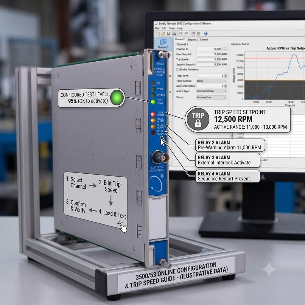
Modifying safety parameters in a machinery protection system requires deep technical caution. In the industrial automation sector, the Bently Nevada 3500/53 Electronic Overspeed Detection System safeguards critical rotating machinery. However, field engineers often debate whether the 3500 Rack Configuration Software allows users to modify the Trip Speed parameter while the turbine is running. The short answer depends on your system configuration, firmware version, and active safety protocols.

The Real Risks of Online Trip Speed Modifications

According to API 670 standards for machinery protection systems, operators should never alter safety-critical setpoints during machine operation. However, the Bently Nevada software environment does not always enforce a hard block on online changes. Depending on your specific system setup, an online download of a modified overspeed setpoint typically triggers one of two technical behaviors.

Scenario 1: Pending Activation Status
In newer firmware versions, the software accepts the configuration download but places the new Trip Speed into a “Pending” state. The module continues to use the old setpoint until the hardware undergoes a manual reset or a power cycle. Field engineers must remember that a “Download Successful” message does not mean the new overspeed protection value is live.

In contrast, older legacy systems or racks with relaxed security permissions might allow immediate execution. In this scenario, the overspeed setpoint changes in real time. If a technician accidentally inputs an incorrect value, the machine could lose its safety margin instantly, risking catastrophic mechanical failure during a transient surge.

Why Independent Overspeed Protection Matters in DCS and PLC Environments

The Bently Nevada 3500/53 module does not serve as a standard speed transmitter. Instead, it operates as an independent safety layer separate from the primary Distributed Control System (DCS) or Programmable Logic Controller (PLC). In factory automation plants, control systems can experience communication lag or processor overruns.

Therefore, the 3500/53 system must act autonomously. If the primary governor control fails, this module executes an emergency trip within milliseconds. This rapid response prevents rotor destruction in high-stakes applications like refinery compressors, steam turbine generators, and LNG expansion trains.

Technical Insights: Voting Logic and Configuration Security

To deliver maximum reliability, the 3500/53 module utilizes advanced voting logic, typically configured in a 2oo3 (Two Out of Three) architecture. Three independent proximity probes measure the shaft speed simultaneously. The system triggers a trip output only when at least two channels confirm an overspeed condition.

If you attempt an online configuration modification and cause a parameter mismatch between channels, you risk disrupting this voting logic. To eliminate this vulnerability, facility managers must enforce strict hardware-based security:

  • Keep the physical rack keyswitch turned to the RUN Position to block unauthorized software writes.
  • Enable software-level configuration locks and password hierarchies.
  • Enforce a strict Management of Change (MOC) policy before connecting any configuration PC.

Installation and Maintenance Best Practices for Field Engineers

Experienced automation professionals follow rigid guidelines when maintaining speed detection hardware. To ensure plant safety, always apply the following field rules:

  1. Execute Changes Only During Shutdown: Schedule all overspeed adjustments during planned maintenance windows when the rotor is completely stationary.
  2. Verify Measurement Units Carefully: Always double-check your units before hitting download. Mistaking Hertz (Hz) for Revolutions Per Minute (RPM), or entering an incorrect gear tooth count, will corrupt the safety calculation.
  3. Audit the System Event Logs: After any configuration upload, review the System Event List to confirm that the hardware accepted the parameters without generating a channel fault.

Powergear X Automation Insight: Hardware Lifecycle Strategy

Our Perspective: At Powergear X Automation, we observe that many industrial sites run Bently Nevada 3500 racks that have been in continuous operation for over a decade. While these systems are remarkably durable, running obsolete firmware creates unnecessary operational risks. Firmware mismatches between old hardware modules and newer PC configuration software frequently cause corrupt downloads or false diagnostics.

We recommend conducting a comprehensive audit of your machinery protection assets every five years. Upgrading your modules ensures full compliance with modern safety standards and guarantees clean integration with your broader plant control systems.

Industrial Application Scenario: Petrochemical Compressor Protection

Consider a large-scale centrifugal compressor driven by a steam turbine in a petrochemical plant. The plant utilizes a Rockwell Automation Allen-Bradley ControlLogix PLC for process sequencing and a Honeywell Experion DCS for continuous loop control. However, the critical overspeed trip logic resides solely in a Bently Nevada 3500 rack equipped with a 3500/53 module configured in 2oo3 voting logic.

During an annual turnaround, engineers needed to update the turbine trip speed from 4,200 RPM to 4,150 RPM based on new OEM design limits. Instead of performing an unapproved online modification while idling, the team utilized the plant’s outage window. They switched the physical rack keyswitch to PROGRAM, verified the tooth-to-frequency scaling factors, uploaded the new configuration, switched the key back to RUN, and simulated a speed signal to validate the trip relays before startup. This disciplined approach prevented accidental trips and ensured complete compliance with insurance and safety regulations.


Frequently Asked Questions

Q1: What happens if a 3500/53 channel experiences a sensor fault during operation?
In a standard 2oo3 configuration, if one proximity probe fails or loses its signal, the module flags a channel fault error but does not trip the machine. The voting logic automatically degrades to a 1oo2 (One Out of Two) safety structure, allowing the plant to continue running safely while maintenance teams replace the faulty sensor.

Q2: Can I mix old firmware modules with new software versions?
While Bently Nevada software provides backward compatibility, severe gaps between old module firmware and modern software versions can block specific parameter changes or cause communication timeouts. Always check the official compatibility matrix before attempting to modify parameters.

Q3: Is the 3500/53 module interchangeable with standard 3500/50 tachometer modules?
No, they serve different purposes. The 3500/50 is a standard tachometer designed for speed measurement, reverse rotation detection, and zero-speed tracking. The 3500/53 is a highly specialized, fast-response safety module dedicated solely to emergency overspeed protection and complies with rigorous international safety standards.


Looking to replace obsolete modules, source certified spare parts, or optimize your industrial control systems? Discover reliable hardware solutions and technical support by visiting Powergear X Automation today.

Bently Nevada 133819-01 vs 133811-02: Isolated I/O Comparison

Bently Nevada 133819-01 vs 133811-02: Solving Temperature Fluctuations in Machinery Protection

Reliable temperature monitoring is crucial for protecting critical rotating machinery from thermal stress. In heavy industrial environments, choosing the correct I/O module prevents catastrophic asset failures. The Bently Nevada 3500/60 temperature monitor relies heavily on these interfaces to deliver accurate data to the primary control systems. However, choosing between the isolated 133819-01 and the non-isolated 133811-02 drastically impacts data stability.

Understanding the Power of Galvanic Isolation in the 133819-01

The Bently Nevada 133819-01 features an isolated I/O architecture designed for harsh industrial automation environments. This module provides complete galvanic isolation between the field sensor wiring and the 3500 system backplane. Consequently, it blocks parasitic electrical noise from corrupting delicate thermocouple and RTD millivolt signals. At Powergear X Automation, our field experience shows that isolation acts as a definitive barrier against unpredictable common-mode voltages.

Why the Non-Isolated 133811-02 Triggers Signal Oscillations

The 133811-02 module lacks internal electrical isolation, making it vulnerable to external electromagnetic interference. Ground potential differences between the field device and the control cabinet create ground loops. These loops inject stray currents into the signal path, causing sudden temperature jumps of 5°C to 20°C. Therefore, users should deploy the 133811-02 only in pristine environments with unified grounding grids.

Mitigating Noise in DCS and PLC Integrated Networks

Modern factory automation heavily integrates temperature monitors with distributed control systems (DCS) and programmable logic controllers (PLC). When sensor cables run parallel to high-power motor feeders or variable frequency drives (VFDs), cross-talk occurs. Non-isolated modules register this electromagnetic interference as random data spikes. Upgrading to the isolated 133819-01 solves these issues without requiring expensive field cable replacements.

Installation Best Practices for Machinery Protection Systems

Engineers must follow precise installation guidelines to maintain signal integrity across critical plant assets:

  • Maintain Single-Point Grounding: Terminate cable shields at one end only to prevent ground loop formation.
  • Enforce Cable Separation: Route low-voltage instrument lines far away from high-current VFD output cables.
  • Deploy External Surge Protection: Install localized lightning surge arrestors for all outdoor sensor runs.

Implementing these steps drastically minimizes nuisance alarms and boosts overall machinery protection reliability.

Author Commentary: The Powergear X Automation Technical Perspective

In our view at Powergear X Automation, relying on non-isolated modules like the 133811-02 in modern facilities introduces unnecessary operational risks. Industrial plants now feature hundreds of switching power supplies and VFDs that saturate local ground grids with high-frequency harmonic noise. Investing upfront in the isolated 133819-01 module significantly reduces troubleshooting hours, prevents false trips, and protects long-term asset health.

If you are looking to upgrade your turbine or compressor monitoring system, you can browse high-quality hardware directly on Powergear X Automation to find reliable, industrial-grade monitoring components.

Real-World Solution Scenario: Resolving Nuisance Trips in a Petrochemical Plant

A major petrochemical processing facility experienced frequent, unexplained high-temperature alarms on a critical centrifugal compressor. The system utilized the non-isolated 133811-02 module connected to 80-meter thermocouple runs. Investigations revealed that the temperature spikes synchronized perfectly with the startup cycle of a nearby 500kW cooling tower motor. The engineering team replaced the interface with the isolated Bently Nevada 133819-01 module. Instantly, the signal variance dropped from ±12°C to a stable ±0.3°C, completely eliminating the costly production shutdowns.

Frequently Asked Questions

Q1: Can I use the 133819-01 as a direct drop-in replacement for the 133811-02?
Yes, functionally they both interface with the 3500/60 monitor card. However, you must verify your specific firmware compatibility version before upgrading.

Q2: What is the maximum recommended cable distance for the non-isolated 133811-02?
We recommend limiting non-isolated sensor cable runs to under 50 meters in low-noise environments to avoid data degradation.

Q3: How do ground loops specifically affect thermocouple readings?
Ground loops create small stray voltages that add to or subtract from the thermocouple’s millivolt output, generating false temperature shifts.

330500 Sensor: Stable Calibration for Industrial Control Systems

330500 Sensor: Stable Calibration for Industrial Control Systems

Why the 330500 Proximitor Sensor Eliminates Periodic Physical Calibration Needs

In the demanding world of industrial automation and machinery protection, maintenance efficiency defines profitability. Traditional sensors often require frequent manual adjustments to combat signal drift. However, the 330500 Proximitor® Sensor breaks this cycle. This article explores the engineering excellence behind its “calibration-free” design and how it optimizes control systems performance.

330500 Sensor: Stable Calibration for Industrial Control Systems

The Stability of Non-Contact Eddy Current Technology

The 330500 utilizes the eddy current principle for high-precision displacement monitoring. Unlike mechanical sensors, it generates an electromagnetic field to measure the gap between the probe and target. Because the sensor never touches the rotating shaft, it avoids physical friction and mechanical fatigue. This non-contact approach ensures the core measurement physics remain unchanged over years of continuous operation.

Precision Factory Matching for Seamless Integration

Bently Nevada designs the 330500 as part of a tightly integrated measurement chain. This system includes the proximity probe, the extension cable, and the Proximitor itself. Engineers calibrate these components as a single unit at the factory. This rigorous process accounts for sensitivity (mV/mil) and linearity across the entire range. Consequently, users gain a “plug-and-play” experience that maintains accuracy without field-level tuning.

Solid-State Electronics Prevent Long-Term Drift

Many legacy factory automation sensors suffer from material creep or aging of internal strain gauges. The 330500 employs advanced solid-state circuitry that resists these common failure modes. The electronic components are selected for their predictable lifecycle and low thermal noise. At Powergear X Automation, we observe that these units maintain their voltage-to-gap ratio even after a decade in high-heat environments.

Robust Design for Harsh Industrial Environments

Reliability in DCS and PLC environments requires protection against external interference. The 330500 features internal temperature compensation and high-grade shielding. These features neutralize the effects of electrical noise and ambient temperature fluctuations. By mitigating environmental impact at the hardware level, the need for seasonal recalibration becomes obsolete.

Streamlined Verification Over Manual Calibration

Modern maintenance teams prioritize verification over physical adjustment. You can verify the 330500 system through simple gap voltage checks or static calibration audits. These steps confirm that the loop is healthy without altering the factory-set parameters. If a reading is off, it usually indicates a loose mounting or a damaged cable rather than a sensor calibration error.

Strategic Advantages Over Traditional Sensors

Traditional contact-based sensors often experience hysteresis or mounting stress. These issues necessitate frequent downtime for technician intervention. The 330500 avoids these pitfalls through its rigid design and stable electronic signature. This shift from reactive calibration to proactive verification significantly lowers the Total Cost of Ownership (TCO) for critical rotating assets.

Author Insights by Powergear X Automation

From our experience at Powergear X Automation, the 330500 represents a shift toward “maintenance-free” instrumentation. While the hardware is remarkably stable, we recommend that users maintain strict records of target material properties. Since eddy current sensors are sensitive to material conductivity and permeability, changing the shaft material will necessitate a system re-evaluation. For those upgrading legacy control systems, the 330500 offers the most reliable path to reducing instrumentation overhead.

Technical Excellence Summary

  • Zero mechanical wear due to non-contact sensing.
  • Factory-matched components ensure high linearity.
  • Solid-state design minimizes electronic signal drift.
  • Built-in compensation handles extreme temperature swings.
  • Verification protocols replace time-consuming physical adjustments.
  • High resistance to industrial electromagnetic interference.

Application Scenarios

  • Steam Turbine Protection: Monitoring radial vibration and axial thrust in high-temperature zones.
  • Centrifugal Compressors: Providing real-time shaft position data to prevent catastrophic bearing failure.
  • Hydroelectric Generators: Measuring air gap and vibration in massive rotating structures.
  • Discover more high-performance solutions for your facility by visiting Powergear X Automation. Our team provides the expertise you need for reliable machinery protection.

Frequently Asked Questions (FAQ)

  • 1. If the sensor is calibration-free, why do I see different voltage readings after a probe replacement?
  • Output variations usually stem from “interchangeability error.” Even high-precision probes have slight manufacturing tolerances. While the Proximitor doesn’t need recalibration, you must verify the new “Average Scale Factor” to ensure it meets your specific alarm setpoints.
  • 2. Can I use a 330500 Proximitor with a different brand’s extension cable?
  • We strongly advise against this. The system’s stability relies on the specific electrical impedance of the matched cable. Using third-party cables will compromise the linearity and void the “calibration-free” status of the system.
  • 3. Does shaft “runout” affect the calibration of the sensor?
  • Runout is a mechanical or magnetic imperfection in the shaft, not a sensor calibration issue. The 330500 accurately measures the runout it “sees.” To fix this, you must treat the shaft surface rather than adjusting the sensor electronics.
Critical Applications of Bently Nevada 330400 Sensors

Bently Nevada 330400: Expert Guide to Machinery Monitoring

The Multifunctional Sentinel: How the 330400 Accelerometer Protects Industrial Assets

In industrial automation, protecting rotating machinery requires sensors that deliver more than basic data. The Bently Nevada 330400 high-performance accelerometer serves as a multifunctional sentinel, providing critical inputs for vibration analysis, position monitoring, and predictive diagnostics. This versatile instrument transforms physical motion into actionable intelligence, enabling engineers to safeguard turbines, compressors, and pumps within complex control systems.

Critical Applications of Bently Nevada 330400 Sensors

Dual-Role Vibration Monitoring: From Impact Detection to Absolute Measurement

The 330400 excels in two key vibration monitoring roles. Primarily, it functions as a high-frequency impact detector, capturing transient events up to 15 kHz that indicate bearing defects or gear tooth issues. Additionally, when used alongside proximity probes, it enables the calculation of true shaft absolute vibration—a critical parameter for assessing machine health on flexible foundations, providing a complete picture that relative displacement measurements alone cannot offer.

Shaft Position and Dynamic Clearance Management

Beyond vibration, the 330400 contributes to precise shaft position analysis. By monitoring casing acceleration during thermal transients and load changes, it helps infer dynamic clearance conditions. This data ensures rotating components maintain safe operating margins within stationary housings, particularly during critical startup and shutdown sequences where thermal growth significantly affects internal clearances in turbines and large compressors.

Proactive Thrust Bearing Protection Through Vibration Signature

Thrust bearing failure ranks among the most catastrophic machinery events. The 330400 provides early warning by detecting the unique high-frequency vibration signature generated during thrust collar contact or excessive loading. This acoustic emission often precedes measurable temperature increases or axial displacement, offering a critical 8-12 hour advance warning that enables protective shutdowns before complete bearing destruction occurs.

Seamless Integration with Modern Protection Architectures

The sensor’s IEPE output integrates directly with contemporary Machinery Protection Systems (MPS) and PLC networks. It feeds specialized monitor modules like the Bently Nevada 3500/70M, which process raw acceleration into parameters like PeakVue and gRMS. These values then trigger automated shutdown logic in the plant DCS, creating a robust safety layer that meets API 670 and other industry standards for critical asset protection.

Enabling Data-Driven Condition-Based Maintenance

The 330400 transforms maintenance strategies from calendar-based to condition-driven. By providing continuous, high-resolution data, it enables:

  • Trend Analysis: Tracking gradual increases in vibration energy to predict remaining useful life.
  • Spectral Diagnostics: Identifying specific fault frequencies for targeted repairs.
  • Performance Benchmarking: Comparing vibration signatures before and after maintenance interventions.

This approach typically reduces maintenance costs by 25-35% while increasing asset availability by 15-20%.

Expert Insight: The Strategic Value of High-Fidelity Data

At Powergear X Automation, we’ve quantified the value of precise acceleration data. In one analysis, plants using 330400 sensors for bearing monitoring detected failures an average of 45 days earlier than those relying solely on overall vibration levels. This early warning translated to a 92% reduction in catastrophic bearing failures and allowed 100% of repairs to be scheduled during planned outages. The sensor’s true value lies not just in data collection, but in the actionable intelligence it provides for strategic maintenance planning.

Application Case: Preventing Turbine Generator Catastrophe

A 500 MW steam turbine generator at a power plant experienced intermittent high-frequency vibration spikes. Standard proximity probes showed normal shaft vibration. Engineers installed 330400 accelerometers on the turbine bearing housings. Data analysis revealed 85 g peak events occurring at 8,200 Hz—the exact calculated frequency for a cracked retaining ring on the generator rotor. The finding prompted an immediate shutdown. Inspection confirmed the crack, preventing a potential rotor burst estimated at $15 million in direct damage plus 90 days of lost generation revenue.

Application Case: Optimizing Compressor Fleet Performance

A natural gas pipeline operator monitored 12 centrifugal compressors with basic vibration switches. After retrofitting with 330400 accelerometers connected to a central monitoring system, they established baseline vibration profiles for each unit. Over 18 months, the data revealed that Compressor #7 showed a 300% increase in high-frequency energy (30-50 gRMS) while overall vibration remained stable. This indicated early rolling element bearing degradation. The bearing was replaced during a planned maintenance window at a cost of $8,500, avoiding an estimated $220,000 in unplanned downtime and secondary damage to the compressor rotor.

Technical Specifications Enabling Diverse Applications

ParameterSpecificationApplication Benefit
Sensitivity100 mV/g ±5%Consistent, strong signal for accurate measurement across applications
Frequency Range1.0 Hz to 15,000 HzCovers both low-speed dynamics and high-frequency bearing/gear faults
Measurement Range±500 g PeakWithstands severe shock loads without saturation
Operating Temperature-50°C to +120°CReliable performance in extreme industrial environments
Output TypeIEPE (2-wire)Simplified integration with standard monitoring systems

Implementation Best Practices

  1. Strategic Placement: Mount on bearing housings in radial and axial orientations for comprehensive coverage.
  2. Rigid Mounting: Use stud mounting on clean, flat surfaces to ensure accurate high-frequency signal transmission.
  3. Proper Cabling: Employ double-shielded coaxial cables with single-end grounding to prevent EMI.
  4. System Configuration: Set appropriate filtering in monitoring software to focus on relevant frequency bands.
  5. Baseline Establishment: Record reference spectra when machinery is newly commissioned or after major overhaul.

Frequently Asked Questions (FAQ)

  • 1. Can the 330400 measure both vibration and position simultaneously?
  • Yes, it provides continuous acceleration data that can be analyzed for vibration characteristics while also being used to infer positional changes during thermal transients, though it does not directly measure displacement like a proximity probe.
  • 2. What is the typical lifespan of a 330400 sensor in continuous operation?
  • With proper installation, expect 5-8 years of reliable service. In extreme conditions (high temperature, corrosive environments), lifespan may reduce to 3-5 years. Annual performance verification is recommended after 3 years.
  • 3. How does the 330400 compare to wireless vibration sensors?
  • The 330400 provides higher data fidelity (up to 15 kHz vs. typically 1-2 kHz for wireless) and continuous real-time monitoring. Wireless sensors offer installation flexibility for temporary or hard-to-wire locations but may compromise on data resolution and update rates.
  • 4. Can this sensor detect electrical faults in motors?
  • Indirectly. It can detect vibration patterns associated with electrical issues like rotor bar defects (pole pass frequency sidebands) or air gap eccentricity. For definitive electrical diagnostics, current signature analysis should complement vibration data.
  • 5. What maintenance does the sensor itself require?
  • Minimal. Periodic checks should include verifying mounting torque, inspecting cable integrity, and checking connector seals. Electrical verification against a portable calibrator every 12-18 months confirms ongoing accuracy.

For expert guidance on implementing comprehensive vibration monitoring with genuine Bently Nevada components, consult the engineering team at Powergear X Automation.

Bently 3500/70M vs. Emerson AMS 6500: Reciprocating Monitor Guide

Protection vs. Diagnostics: Choosing the Right Monitor for Critical Reciprocating Assets

Selecting a monitoring system for reciprocating compressors is a strategic decision impacting safety, reliability, and cost. The Bently Nevada 3500/70M Reciprocating Compressor Monitor and the Emerson AMS 6500 Atterex™ represent two distinct philosophies: dedicated hardware protection versus advanced software diagnostics. This analysis contrasts their core architectures to guide engineers in optimizing their industrial automation strategy for high-stakes machinery.

Bently 3500/70M vs. Emerson AMS 6500: Reciprocating Monitor Guide

Core Philosophy: Dedicated Protection vs. Analytical Flexibility

The Bently Nevada 3500/70M is engineered as a hardwired protection system. Its primary mandate is to prevent catastrophic failure through continuous, high-speed monitoring and direct relay tripping. The Emerson AMS 6500 functions as a high-fidelity diagnostic data acquirer, designed to integrate deeply with plant networks for long-term trend analysis and predictive maintenance within the broader DeltaV ecosystem.

Architectural Comparison: Hardware Integration & Safety

A fundamental differentiator is safety integration. The 3500/70M executes protection logic within its ruggedized rack, capable of initiating a safety shutdown (trip) within 10-50 milliseconds independently of any external DCS or PLC. The AMS 6500, while providing alarms, typically requires a separate Safety Instrumented System (SIS) or the plant DCS to execute a trip, adding layers that can increase latency and complexity to the safety loop.

Data Acquisition & Reciprocating-Specific Processing

For reciprocating machinery, data synchronized to the crankshaft angle is non-negotiable. The 3500/70M uses a dedicated Keyphasor (often with Multiple Events Per Turn) to lock every vibration sample to a precise piston position. It employs specialized algorithms for Rod Drop, Cylinder Pressure, and Crosshead Pin Position. The AMS 6500 excels at spectral analysis but may require significant application engineering to achieve the same level of kinematic synchronization and reciprocating-specific parameter extraction.

Diagnostic Depth and Analytical Tools

The Emerson AMS 6500, coupled with its analytics software, offers superior long-term data historization and advanced pattern recognition. It is exceptional for fleet-wide trend analysis and correlating vibration with process variables. The Bently Nevada solution, when integrated with System 1™ software, provides deep diagnostic plots like PV (Pressure-Volume) diagrams and polar orbits specifically for reciprocating machines, but its strength remains real-time, on-edge detection of immediate mechanical faults.

Reliability, Standards, and Environmental Hardening

The 3500 platform is explicitly designed to meet API 670 Standard for machinery protection systems. Its components are hardened for extreme environments (Class I, Div 2 hazardous areas, wide temperature ranges). The AMS 6500 is a robust industrial device but is often viewed through the lens of the API 670 standard as part of a condition monitoring system, not always as the primary, certified protection layer for the most critical compressors.

Expert Analysis: Matching System to Asset Criticality

At Powergear X Automation, we base recommendations on consequence of failure. For a critical high-pressure hydrogen recycle compressor where a rod failure could cause a $5M+ process incident, the 3500/70M’s deterministic protection is mandatory. For a less critical cooling water pump, the AMS 6500’s diagnostic power and network integration offer better lifecycle value. The trend is toward hybrid architectures: using the 3500/70M for protection and an AMS 6500 for deep diagnostics on the same asset.

Technical Feature Comparison Table

FeatureBently Nevada 3500/70MEmerson AMS 6500
Primary RoleMachinery Protection & Safety ShutdownCondition Monitoring & Advanced Diagnostics
Trip ExecutionDirect, independent hardware relayTypically via external DCS/SIS
Key Reciprocating MetricsRod Drop, Cylinder Pressure, Dynamic LoadOverall Vibration, Spectra, Waveforms
Data SynchronizationCrank-angle resolved (hardware-based)Time-based; angle-resolved requires setup
Integration StandardAPI 670 (Protection Focus)Open Networking (ODC, Ethernet/IP)
Typical DeploymentSingle, critical assetsFleet-wide monitoring networks

Application Case: LNG Plant Propane Compressor

An LNG facility faced repeated, unexplained shutdowns on a critical 8-throw reciprocating propane compressor. An AMS 6500 was installed for diagnostics, revealing complex harmonic content but no clear root cause. A 3500/70M was then added for protection. Its rod load monitoring, synchronized to crank angle, immediately identified a failing piston rider ring causing abnormal side-loading 40 degrees before top dead center. The precise data allowed scheduling a repair during a planned turnaround, avoiding an estimated $1.2M in lost production from an unplanned trip.

Application Case: Pipeline Gas Storage Facility

A pipeline operator with 30+ older reciprocating engines implemented a cost-effective fleet monitoring strategy. They installed AMS 6500 monitors across all units, feeding data to a centralized analytics platform. This provided excellent trend data and identified two engines with deteriorating performance. Based on this, they then installed dedicated 3500/70M systems on those two high-risk engines for enhanced protection. This layered, risk-based approach optimized capital expenditure while ensuring safety.

Total Cost of Ownership & Implementation Considerations

Initial cost for a 3500/70M point is typically higher due to its rugged hardware and certification. However, for critical assets, its ability to prevent a single catastrophic failure delivers an immediate ROI. The AMS 6500 offers a lower cost per point at scale and reduces long-term diagnostic labor through its software analytics. The decision often boils down to this question: Is the primary need to prevent a disaster (choose Bently) or to understand degradation over time (choose Emerson)?

Frequently Asked Questions (FAQ)

Which system is better for unmanned or remote monitoring stations?

Both can support remote comms. The 3500/70M is often favored in harsh, unmanned locations due to its proven hardware reliability and lower dependency on network stability for its core protection function. The AMS 6500 requires more robust network infrastructure for full functionality.

Does the AMS 6500 support monitoring of cylinder pressure and rod position?

It can accept the analog signals from pressure transducers and LVDTs used for these measurements. However, it does not contain the dedicated, pre-packaged algorithms of the 3500/70M to calculate derived parameters like rod load or deviation from ideal PV diagrams. This analysis would need to be done in higher-level software.

Is it common to see both systems installed on the same compressor?

Increasingly, yes, especially on hyper-critical assets. This architecture leverages the 3500/70M for fail-safe protection and the AMS 6500 for deep diagnostic data mining and integration with plant-wide performance and reliability platforms.

How do the systems handle sensor compatibility and conditioning?

The 3500/70M is optimized for Bently Nevada’s proprietary Velomitor® and accelerometer families, offering plug-and-play compatibility. The AMS 6500 supports a wider range of third-party IEPE sensors natively, offering greater flexibility in sensor selection for non-critical parameters.

For a detailed assessment of your machinery protection needs, consult the application engineers at Powergear X Automation to select the optimal monitoring architecture.

Back to Top
Product has been added to your cart