Over 50,000 hot-selling automation module components.
Preventing Industrial EMI CC-TDI110 Installation Best Practices_

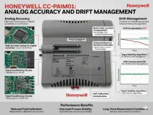
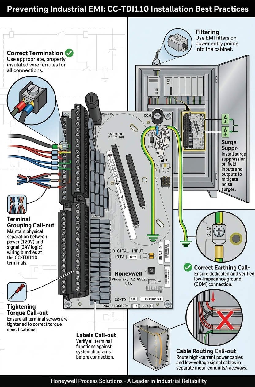
Preventing Industrial EMI: CC-TDI110 Installation Best Practices

Maximizing Signal Reliability with the Honeywell CC-TDI110 Digital Input Module

The Core Role of Digital Inputs in DCS Reliability

Modern industrial automation relies on precise data acquisition from field devices to the Distributed Control System (DCS). The Honeywell CC-TDI110 Digital Input Module serves as a critical bridge in this communication chain. Specifically, it excels in high-power environments like petrochemical plants and heavy manufacturing lines. Maintaining signal integrity is paramount in these settings. Consequently, engineers must prioritize proper shielding to prevent costly false trips or missed alarms.

Preventing Industrial EMI CC-TDI110 Installation Best Practices_

Preventing Industrial EMI CC-TDI110 Installation Best Practices_

Enhancing Isolation Against Electromagnetic Interference

The CC-TDI110 features robust channel-to-channel and channel-to-ground isolation. This design allows the module to detect digital states accurately despite nearby high-voltage cables. However, isolation alone cannot solve all noise problems. Electrical noise often originates from poor cable routing rather than internal component failure. Therefore, system integrators should treat internal isolation as a secondary defense rather than a primary solution.

Managing Common-Mode Noise in VFD Environments

Industrial facilities frequently utilize large motors and Variable Frequency Drives (VFDs). These devices generate significant Common-Mode Interference that can overwhelm standard control systems. The CC-TDI110 offers a high tolerance to this noise, ensuring stable performance. Nevertheless, if signal cables sit too close to power lines, induced voltages might exceed these rejection thresholds. Reliable factory automation requires a strict physical separation between signal and power conductors.

Advanced Input Filtering and Debounce Mechanisms

Transient noise can trigger nuisance alarms if a module lacks proper filtering. The CC-TDI110 addresses this through configurable debounce times that suppress short-lived electrical spikes. While these filters improve stability, they are not a cure for chronic interference. Excessive noise persisting beyond the filter window can still cause unintended shutdowns. As a result, Powergear X Automation recommends validating filter settings during the commissioning phase.

Best Practices for Shielded Cable Installation

Proper installation is the foundation of long-term system stability. When routing signals near motor feeders or lines exceeding 220V AC, always use shielded twisted-pair cables. Maintain at least 300 mm of clearance according to IEC 61000-5-2 guidelines. Furthermore, ensure any unavoidable crossings occur at a 90-degree angle. This technique effectively minimizes inductive coupling and preserves the purity of the digital signal.

Critical Shield Grounding and Segregation Strategies

A frequent mistake in the field involves grounding cable shields at both ends. This creates ground loops that introduce more noise into the system. For the CC-TDI110, engineers should ground the shield only at the DCS cabinet. Additionally, never share cable trays between high-current power lines and sensitive signal wires. We have observed cases where segregating cables into dedicated metallic trays instantly resolved intermittent DI flickering.

Strategic Insights from Powergear X Automation

In our experience at Powergear X Automation, hardware quality is only half the battle. The CC-TDI110 is a world-class module, but its performance depends on the surrounding infrastructure. We recommend a “holistic shielding” approach that combines high-quality Honeywell hardware with strict adherence to IEC standards. Investing in proper wiring today prevents expensive downtime in the future.

Technical Summary Checklist

  • Use shielded twisted-pair cables for all digital inputs.
  • Ground shields at the DCS side only to prevent loops.
  • Maintain 300 mm separation from high-power cables.
  • Configure debounce times to match field device characteristics.
  • Install Surge Protection Devices (SPD) in lightning-prone areas.

Practical Application Scenarios

  • Refinery Safety Interlocks: Ensuring emergency shutdown valves report status without EMI-induced false positives.
  • Power Plant Turbine Control: Monitoring high-speed digital states near heavy electrical switching equipment.
  • Chemical Batch Processing: Maintaining accurate sequence control where VFDs are used extensively for agitation.

Expert FAQ: CC-TDI110 Implementation

Q1: How do I choose between the CC-TDI110 and legacy Honeywell DI modules?
Evaluate your current electromagnetic environment first. While the CC-TDI110 is often backward compatible, it offers superior noise rejection features necessary for modern VFD-heavy plants. If your facility has upgraded its power hardware, upgrading your I/O modules is a wise technical move.

Q2: What is the most common cause of “flickering” signals in new installations?
Usually, it is a grounding issue. Ensure your shields are not creating loops and check for 90-degree crossings at power intersections. If the issue persists, increase the software debounce time slightly within the DCS configuration.

Q3: Does this module require specialized maintenance during its lifecycle?
The CC-TDI110 is largely maintenance-free. However, we recommend annual inspections of the terminal blocks and grounding bars. Loose connections are a silent killer of signal integrity in high-vibration industrial settings.

Honeywell CC-PWRN01 Guide Thermal Management in DCS Cabinets

Honeywell CC-PWRN01 Guide: Thermal Management in DCS Cabinets

Ensuring DCS Stability: Thermal Management for the Honeywell CC-PWRN01 Power Module

The Critical Role of Reliable Power in Industrial Automation

The Honeywell CC-PWRN01 power module provides essential redundant energy to modern Distributed Control Systems (DCS). It secures continuous operations in demanding sectors like oil, gas, and pharmaceutical production. However, system reliability depends heavily on proper thermal management. Overheating remains a leading cause of premature component failure in industrial environments. Therefore, engineers must prioritize vertical installation spacing to maintain long-term system health.

Honeywell CC-PWRN01 Guide Thermal Management in DCS Cabinets

Honeywell CC-PWRN01 Guide Thermal Management in DCS Cabinets

Optimizing Vertical Spacing for Natural Convection

For the CC-PWRN01, maintaining a vertical clearance of 50–75 mm is vital for air circulation. Natural convection moves heat from the bottom to the top of the cabinet. If you obstruct this flow, internal temperatures may exceed the +70°C design limit. Moreover, restricted airflow significantly shortens the lifespan of sensitive electrolytic capacitors. In our experience, tight spacing creates hot spots that sit 15°C above the ambient cabinet temperature.

Managing Load Capacity to Reduce Heat Generation

Power modules generate substantially more heat when operating at peak capacity. Continuous high-load conditions accelerate the aging process of internal electronics. As a result, the risk of cascading failures in redundant configurations increases. At Powergear X Automation, we suggest designing systems for 60–70% of the nominal load. This conservative approach provides a safety buffer during seasonal temperature spikes or ventilation issues.

Adapting Cabinet Ventilation for Harsh Climates

The CC-PWRN01 typically relies on passive cooling within the control cabinet. Sealed or high-IP-rated enclosures require even larger spacing to prevent heat accumulation. In regions like the Middle East or Southeast Asia, ambient heat demands stricter standards. We frequently increase vertical spacing to ≥80 mm for these high-temperature projects. Furthermore, integrating heat exchangers or fan trays becomes mandatory when passive cooling reaches its physical limits.

Installation Best Practices for Power Modules

Proper physical placement ensures that heat does not affect other critical system components. Engineers should always stack power modules vertically to align with natural airflow. Additionally, avoid placing sensitive controllers or I/O processors directly above a heat-generating power supply. We once resolved recurring communication faults in a refinery by simply relocating a controller away from a module’s heat path. These small adjustments prevent significant thermal stress on the entire DCS architecture.

Routine Maintenance and Thermal Inspection Strategies

Regular inspections keep your factory automation system running at peak efficiency. Use infrared thermometers to measure the surface temperature of the CC-PWRN01 during operation. If surface readings exceed 65°C, you must immediately investigate airflow obstructions or spacing issues. Moreover, dust accumulation can reduce heat dissipation efficiency by up to 20%. Therefore, cleaning internal components during scheduled shutdowns is a simple yet effective reliability strategy.

Professional Insights from Powergear X Automation

At Powergear X Automation, we believe that thermal design is as important as electrical wiring. Modern power modules like the CC-PWRN01 are highly efficient, but they still follow the laws of thermodynamics. Neglecting a few centimeters of space can lead to millions in lost production due to an unexpected trip. We recommend a comprehensive thermal audit for every cabinet upgrade to ensure modern hardware performs within its optimal environment.

Technical Installation Checklist

  • Maintain a minimum of 50–75 mm vertical clearance between units.
  • Mount modules vertically to support natural bottom-to-top airflow.
  • Use perforated cable ducts to avoid trapping heat near the module.
  • Avoid tight cable bundling directly above the power supply vents.
  • Verify that the total load stays under 75% for unventilated cabinets.

Industrial Application Scenarios

  • Offshore Platforms: Maintaining redundant power in compact, high-ambient-temperature control rooms.
  • Chemical Processing: Preventing thermal-induced shutdowns in sealed cabinets protected from corrosive gases.
  • Pharmaceutical Batching: Ensuring high-availability power for critical sequence controllers during long production cycles.

Expert FAQ: CC-PWRN01 Implementation

Q1: How do I verify if my current cabinet spacing is sufficient?
If your vertical spacing is ≥50 mm and the cabinet interior stays below 40°C under full load, your setup is generally safe. However, if you notice the module shell feels excessively hot to the touch, consider increasing the gap to 80 mm or adding an exhaust fan to the cabinet roof.

Q2: Can I replace legacy Honeywell power supplies with the CC-PWRN01 directly?
While they are often mechanically compatible, never skip a thermal audit. Newer modules might have higher power densities and different heat profiles than 20-year-old units. Ensure the existing cabinet layout can handle the heat dissipation of the new module before finalizing the retrofit.

Q3: What are the signs of a power module failing due to heat?
Look for discolored plastic housing, bulging capacitors visible through the vents, or frequent “redundancy lost” alarms. If you detect a sweet or burnt smell during a cabinet inspection, the module is likely overheating and requires immediate replacement to avoid a total system failure.

For more technical guides and high-quality automation components, visit Powergear X Automation today.

Honeywell CC-TAIX51 Guide: Solving Humidity-Induced Packet Loss

Reducing Packet Loss in Honeywell CC-TAIX51 Analog Input Modules

The Importance of Precision in Critical Process Industries

The Honeywell CC-TAIX51 analog input module provides high-precision signal acquisition for complex Distributed Control Systems (DCS). It serves vital sectors like oil & gas, pharmaceuticals, and chemical processing. However, high-humidity environments often trigger unexpected communication packet loss. This issue undermines system reliability and causes delayed control responses. Understanding these environmental triggers helps engineers prevent intermittent faults and maintain continuous production cycles.

How Micro-Condensation Disrupts Factory Automation Hardware

Standard industrial ratings often cover humidity levels up to 95% non-condensing. Nevertheless, rapid temperature shifts inside control cabinets create micro-condensation on PCB surfaces. Moisture forms conductive paths between sensitive communication traces. Consequently, this leads to signal distortion or transient short circuits. In fast PID control loops, even minor data acquisition delays can destabilize the entire process.

Maintaining Signal Integrity and Isolation Barriers

The CC-TAIX51 relies on high-impedance circuits to ensure accurate analog data. Humid conditions increase leakage current across these critical isolation barriers. As a result, insulation resistance drops and the signal-to-noise ratio (SNR) weakens. While analog values might only fluctuate slightly, the internal I/O link often suffers. This manifests as checksum failures and data retransmissions at the controller level.

Protecting High-Speed Backplane Communication Stability

These modules communicate with the DCS controller via high-speed backplane interfaces. Humidity and airborne contaminants quickly oxidize these metal connectors. Increased contact resistance introduces timing jitter or bit errors during data transfer. Therefore, communication drops occur more frequently under high system loads. Regular hardware inspection remains the best defense against these physical layer failures.

Optimizing Control Cabinet Climate Management

Field experience shows that climate control is more effective than simple sealing. We recommend installing anti-condensation heaters inside every critical cabinet. Technicians should maintain the internal temperature at least 5°C above the ambient dew point. Sealed IP-rated enclosures without thermal regulation often trap moisture inside. Proper airflow management ensures long-term reliability for all factory automation components.

Implementing Conformal Coating and Connector Care

For offshore or coastal installations, factory-applied conformal coating provides essential protection. Ensure all coatings comply with the IEC 61086 standard for industrial electronics. During maintenance shutdowns, use non-residue contact cleaners on backplane connectors. Re-seating modules restores proper contact pressure and clears oxidation. Powergear X Automation observers suggest that many “failed” modules only require professional cleaning to resume service.

Expert Analysis from Powergear X Automation

At Powergear X Automation, we believe environmental management defines hardware lifespan. The CC-TAIX51 is a robust component, but it cannot overcome poor cabinet design. Engineers should prioritize proactive thermal monitoring over reactive module replacement. Combining high-quality Honeywell hardware with rigorous maintenance standards significantly reduces total cost of ownership. Visit our website for more technical solutions and high-reliability automation hardware.

Technical Maintenance Checklist

  • 🔧 Install internal heaters to prevent micro-condensation.
  • 🔧 Maintain temperature 5°C above the local dew point.
  • 🔧 Use gold-plated or sealed connectors in high-corrosion zones.
  • 🔧 Verify firmware compatibility before swapping legacy modules.
  • 🔧 Schedule annual connector cleaning with non-residue agents.

Solution Scenario: Coastal Refinery Deployment

  • The Challenge: Intermittent “I/O Link Failure” alarms during morning temperature shifts.
  • The Discovery: Micro-condensation on the backplane due to high ambient salt-mist humidity.
  • The Fix: Installed regulated heaters and switched to conformal-coated CC-TAIX51 units.
  • The Result: Communication packet loss dropped to zero within the first 30 days.

Frequently Asked Questions

Q1: Why does my DCS report packet loss when the module seems powered on?
Communication requires much higher signal purity than simple power delivery. Humidity increases contact resistance, causing “bit-flip” errors that the DCS rejects as invalid packets. Powergear X recommends checking the backplane pins for discoloration first.

Q2: Is it better to replace an old module or improve cabinet cooling?
If the environment exceeds 95% humidity, a new module will eventually fail too. Improve the cabinet climate control first. However, if the old module shows visible corrosion on the gold fingers, replacement is necessary to prevent damaging the backplane.

Q3: How do I verify if my CC-TAIX51 is compatible with a legacy rack?
Always check the Honeywell hardware compatibility matrix for your specific firmware revision. Older racks may lack the modern shielding required for high-speed digital communication. In humid plants, consider upgrading the I/O base along with the module.

Honeywell CC-TAIN11 Guide Non-HART Loop Optimization

Honeywell CC-TAIN11 Guide: Non-HART Loop Optimization

Optimizing Honeywell CC-TAIN11 Performance for Non-HART Analog Loops

The Role of CC-TAIN11 in Modern DCS Architecture

The Honeywell CC-TAIN11 base provides essential termination for analog signals within Distributed Control Systems (DCS). It ensures stable data transmission for critical processes in the petrochemical and pharmaceutical sectors. However, engineers often face challenges when integrating non-HART field instruments. Maintaining 4–20 mA signal integrity remains the top priority for system reliability. Improper termination frequently leads to signal drift or control loop instability during high-demand operations.

Honeywell CC-TAIN11 Guide Non-HART Loop Optimization

Honeywell CC-TAIN11 Guide Non-HART Loop Optimization

Understanding HART vs. Non-HART Signal Requirements

Standard HART-enabled loops require a 250 Ω resistance to support digital communication over analog signals. For non-HART instruments, this digital layer does not exist. Adding an extra resistor in these cases is usually unnecessary. Moreover, redundant resistors increase the voltage drop across the circuit. This may reduce the overall accuracy of your factory automation sensors. Therefore, you must verify the input impedance of your AI module before modifying the hardware.

Managing Loop Resistance and Signal Saturation

Every 4–20 mA loop has a maximum load capacity, typically between 500 Ω and 750 Ω. If the total resistance exceeds the transmitter’s limit, the signal may saturate at high current levels. This saturation causes incorrect process readings during peak flow or pressure conditions. As a result, critical safety systems might fail to trigger appropriately. Always calculate the total budget of your loop resistance to ensure linear performance across the entire range.

Redundancy in Honeywell AI Module Design

Most modern Honeywell analog input modules already include precision internal resistors. These components handle the current-to-voltage conversion internally. Consequently, adding external resistors to the CC-TAIN11 is often redundant for standard transmitters. While legacy systems might require impedance matching, modern DCS platforms simplify this process. We recommend checking the specific technical manual for your AI module to confirm its internal configuration.

Best Practices for Field Commissioning and Maintenance

Success in the field requires a methodical approach to loop validation. Powergear X Automation suggests following these technical steps to ensure peak performance:

  • ✅ Use a calibrated multimeter to measure total loop resistance.
  • ✅ Verify the compliance voltage of the field transmitter.
  • ✅ Ensure single-point grounding to prevent EMI-induced fluctuations.
  • ✅ Inspect shield continuity for cable runs exceeding 300 meters.
  • ✅ Confirm the AI module impedance before adding any hardware.

Strategic Insights from Powergear X Automation

Our team at Powergear X Automation observes that 90% of signal issues stem from over-engineering. Many technicians add resistors by default without performing loop calculations. This habit often creates “ghost” faults that are difficult to diagnose later. We believe that a leaner, data-driven installation approach improves long-term stability. Always prioritize the manufacturer’s loop diagrams over generic field assumptions.

Practical Solution Scenarios

  • Refinery Long-Distance Loops: Minimizing resistance in 500m runs to prevent transmitter power failure.
  • Pharmaceutical Batch Control: Ensuring high-precision 4-20mA feedback without digital noise interference.
  • Heavy Industrial EMI Zones: Utilizing the CC-TAIN11 with robust shielding to protect sensitive analog data.

Expert FAQ: CC-TAIN11 Implementation

Q1: Will adding a 250 Ω resistor improve signal stability for non-HART devices?
Actually, it usually does the opposite. If your AI module already has an internal resistor, adding another one creates a parallel or series load that distorts the signal. Only add a resistor if your specific receiving equipment lacks an internal 250 Ω impedance.

Q2: How do I identify a “saturated” loop during plant startup?
Watch for signals that “flat-line” at roughly 18-19 mA even when process conditions increase. This typically indicates that the transmitter cannot push enough voltage through the high loop resistance. Removing unnecessary resistors on the CC-TAIN11 often fixes this immediately.

Q3: Can I use the CC-TAIN11 for third-party PLC integration?
Yes, but you must validate the wiring topology. Third-party PLCs often have different input impedances than Honeywell systems. Always perform a Loop Check (FAT) to ensure the 4-20mA scaling matches between the field device and the controller.

For high-quality components and expert technical support, visit the Powergear X Automation website for all your industrial automation needs.

FC-TSDI-1624 Module: Enhancing SIL Reliability in Process Safety

FC-TSDI-1624 Module: Enhancing SIL Reliability in Process Safety

Optimizing Functional Safety: The Critical Role of the FC-TSDI-1624 in Modern Industrial Architectures

In the high-stakes world of industrial automation, maintaining Safety Integrity Levels (SIL) requires hardware that excels under extreme conditions. The Honeywell FC-TSDI-1624 stands as a cornerstone for Safety Manager and FSC systems. This remote-mounted Safe Digital Input module bridges the gap between field instrumentation and central logic solvers. By acquiring signals from hazardous areas, it ensures process uptime while protecting human life and environmental assets.

FC-TSDI-1624 Module: Enhancing SIL Reliability in Process Safety

FC-TSDI-1624 Module: Enhancing SIL Reliability in Process Safety

The Core Functionality of the FC-TSDI-1624 Module

The FC-TSDI-1624 serves as a high-integrity interface for digital field devices such as emergency stop buttons, pressure switches, and flame detectors. Unlike standard PLC inputs, this module features internal self-diagnostics to detect “stuck-at” faults or cross-talk. It processes 24VDC signals and communicates status updates directly to the safety controller backplane. This architecture allows engineers to monitor critical inputs with millisecond precision, ensuring rapid response during a shutdown event.

Technical Principles: Managing Signal Integrity Across Distances

Remote mounting offers flexibility but introduces physical challenges like voltage drop and electromagnetic interference (EMI). The module utilizes filtered input circuits to mitigate high-frequency noise from nearby equipment. However, loop resistance remains a primary constraint for copper-based installations. When distances exceed standard cabinet boundaries, signal distortion can lead to nuisance trips. Therefore, maintaining a strict grounding topology is essential to prevent common-mode noise from corrupting digital states. Expert teams at Powergear X Automation Limited often emphasize that the quality of the cable shield termination is as vital as the module itself.

EMC Tolerance and Safety Availability in Harsh Environments

Industrial facilities often house Variable Frequency Drives (VFDs) and high-power motors that generate significant electrical noise. The FC-TSDI-1624 is engineered with robust EMC shielding to operate reliably in these “noisy” environments. Despite its high tolerance, poor installation practices can compromise safety availability. For instance, routing signal cables parallel to high-voltage power lines often induces transient voltages. These transients may trigger false Sequence of Events (SOE) logs, complicating post-incident analysis. Proper segregation of cable trays ensures the module maintains its certified diagnostic coverage without interruption.

Strategic Engineering Insights from Powergear X Automation Limited

At Powergear X Automation Limited, we have observed that many system failures stem from “hidden” communication instabilities during brownfield expansions. While the FC-TSDI-1624 is highly versatile, extending its reach via standard copper interconnects beyond recommended limits is risky. We suggest that for distances exceeding 50 meters, users should consider fiber-optic remote I/O nodes. This approach eliminates grounding potential differences between buildings. Our experience suggests that a proactive EMC survey during the Front-End Engineering Design (FEED) stage saves significant costs during the commissioning phase.

Key Technical Maintenance Best Practices

  • Use Shielded Twisted Pairs: Always utilize individually shielded cables to minimize cross-channel interference.
  • Single-Point Grounding: Terminate shields at a designated reference point to avoid destructive ground loops.
  • Vibration Resistance: Secure all wiring mechanically in high-vibration areas like turbine or compressor skids.
  • Surge Protection: Install external lightning arrestors for any signal lines originating from outdoor tank farms.
  • Firmware Alignment: Ensure the module revision matches the Safety Manager controller version to prevent diagnostic mismatches.

Comparative Analysis: Choosing the Right Installation Strategy

When selecting the FC-TSDI-1624, buyers must distinguish between local mounting and remote-node deployment. Local mounting is cost-effective for small-scale skids where the controller is nearby. Conversely, remote-mounted configurations are superior for sprawling refineries as they reduce the “marshalling footprint.” However, remote mounting requires more rigorous documentation for SIL validation. If your project involves heavy VFD usage or multiple grounding zones, the existing wiring infrastructure may require a complete redesign to support modern safety standards.

Application Scenarios and Solutions

The FC-TSDI-1624 is widely deployed in offshore oil platforms where space is a premium. In these environments, the module is placed in specialized explosion-proof enclosures near the wellhead. Another common application is in pharmaceutical batch processing, where frequent cleaning and high humidity require robust I/O protection. By placing the FC-TSDI-1624 closer to the process, plants reduce the volume of cabling returning to the main control room, significantly lowering fire load and installation costs.

For more technical specifications or to secure genuine Honeywell safety components, visit the official Powergear X Automation Limited website for expert assistance.

Frequently Asked Questions (FAQ)

1. Why am I seeing intermittent SOE alarms even though the field switch is stable?
This is often caused by electromagnetic induction or poor shield grounding. If the signal cable runs parallel to a VFD output, the “noise” can mimic a digital transition. Verify your cable segregation and ensure the shield is grounded at only one end.

2. Can I swap an older TSDI module with the FC-TSDI-1624 without software changes?
While they may be mechanically compatible, safety systems require firmware verification. You must check the “Approved Interoperability List” for your specific Safety Manager version. Failure to do so could invalidate your SIL certification.

3. How does distance affect the SIS proof-testing process?
Longer distances increase the complexity of loop resistance testing and diagnostic verification. Properly segmented remote I/O nodes allow technicians to test smaller sections of the loop independently, which speeds up the turnaround schedule significantly.

ABB CI630 Communication Interface: Optimizing Advant OCS Networks

ABB CI630 Communication Interface: Optimizing Advant OCS Networks

Enhancing Connectivity in Advant OCS Systems: The Essential Role of the ABB CI630 Communication Interface

Establishing Stable Data Highways in Industrial Automation

The ABB CI630 communication interface module functions as a critical bridge within the Advant OCS architecture. It facilitates high-speed, deterministic data exchange between controllers, such as the AC450 or AC460, and remote I/O systems. In sectors like power generation and petrochemicals, reliable communication remains a top priority. Consequently, the CI630 ensures that field data reaches the Distributed Control System (DCS) without interruption or corruption.

ABB CI630 Communication Interface: Optimizing Advant OCS Networks

Seamless Integration via MasterBus and Advant Fieldbus Protocols

The CI630 natively supports ABB proprietary protocols, including MasterBus 300 and Advant Fieldbus. This compatibility allows engineers to integrate legacy hardware with modern nodes without costly system overhauls. Moreover, these protocols provide a deterministic environment, which is vital for closed-loop regulation and safety-critical tasks. Choosing the wrong interface for third-party hardware often leads to latency or complete communication failure. Therefore, verifying the network topology remains an essential first step in any system upgrade.

Impact of Response Time on Process Control Precision

Communication refresh rates directly dictate the effectiveness of the entire DCS scanning cycle. For high-speed processes like combustion control or chemical reactions, every millisecond matters. Lower latency results in faster alarm triggers and more stable PID performance. However, high bus loads can cause jitter, leading to intermittent control fluctuations. Many technicians mistakenly blame PID parameters for stability issues when the root cause is actually bus congestion managed by the interface module.

Engineering Resilience Against Harsh Industrial Environments

Modern factory automation requires hardware that survives extreme conditions. The CI630 design emphasizes high Electromagnetic Compatibility (EMC) and temperature resistance. It reduces bit error rates in high-interference zones like power substations. As a result, the system experiences fewer packet retransmissions and less unplanned downtime. Despite its robust build, we recommend using shielded cables and proper grounding when installing modules near variable frequency drives (VFDs) to maintain peak signal integrity.

Best Practices for Installation and Maintenance

Data suggests that over 60% of communication faults stem from improper grounding and environmental factors. To ensure long-term reliability, follow these technical guidelines:

  • Grounding Management: Implement single-point grounding to prevent ground loops.
  • Shielding Integrity: Ensure the communication cable shield connects firmly at the control cabinet side.
  • Cable Routing: Maintain a minimum clearance of 20–30 cm between communication and power lines.
  • Mechanical Security: Use DIN rail clamps and locking terminals in high-vibration areas like compressor stations.
  • Surge Protection: Install dedicated Fieldbus surge arresters for long-distance outdoor communication links.

Expert Commentary from Powergear X Automation Limited

At Powergear X Automation Limited, we believe the CI630 is more than a spare part; it is a vital asset for lifecycle management. While ABB has moved many Advant modules into later lifecycle phases, the CI630 remains a preferred choice for bridging existing infrastructure toward the 800xA platform. We often observe that “intermittent” faults are usually symptoms of aging infrastructure rather than module failure. Thus, a proactive replacement strategy for mission-critical nodes is highly recommended to avoid catastrophic production losses.

Real-World Application Scenarios

  • Petrochemical Refining: Ensuring synchronized data across multiple AC450 controllers for complex distillation processes.
  • Utility Power Plants: Providing redundant communication paths to maintain turbine control during electrical transients.
  • Continuous Manufacturing: Reducing Mean Time to Repair (MTTR) by using hot-swappable communication interfaces in active loops.

Frequently Asked Questions (FAQ)

Q: How do I know if my CI630 module requires an immediate firmware update?
If you are introducing newer AC400 series controllers into an older network, firmware mismatches often cause synchronization errors. Check the revision history; if your module is several versions behind, it may not support the latest redundancy protocols required for modern DCS stability.

Q: Can the CI630 be replaced while the system is powered on?
While the hardware may support physical insertion, we advise caution. In redundant configurations, you must verify that the secondary module has taken full control of the bus before removal. Performing a “hot standby test” during scheduled maintenance is the safest way to validate this capability.

Q: What is the most effective way to troubleshoot “Communication Timeout” errors?
Start by checking the bus terminator resistance. A missing or damaged terminator causes signal reflection. If the physical layer is intact, use a protocol analyzer to check for high bus utilization rates. Often, adding too many nodes to a single CI630 interface exceeds its optimal processing capacity.

For high-quality ABB components and expert technical support, visit the official Powergear X Automation Limited website to secure your industrial supply chain.

ABB S800 I/O Integration Guide: CI532 vs CI522A Comparison

Strategic Integration of ABB S800 I/O: Navigating the CI532 and CI522A Selection

The Vital Role of Communication Interfaces in Multi-Vendor Systems

In modern industrial automation, the ability to bridge disparate hardware ecosystems determines system flexibility. The ABB CI532 and CI522A represent two distinct paths for S800 I/O connectivity. While they look similar, their underlying protocols serve completely different architectural roles. For engineers integrating ABB I/O with third-party controllers like Siemens or Rockwell, making the wrong choice leads to costly communication bottlenecks. Consequently, understanding these functional boundaries is essential for maintaining a lean and responsive control network.

How to Connect ABB S800 I-O to Third-Party PLCs Using CI532

How to Connect ABB S800 I-O to Third-Party PLCs Using CI532

CI532: The Universal Bridge for Third-Party PLC Integration

The CI532 functions as a high-performance PROFIBUS DP-V0/V1 slave interface. This standardization allows the S800 I/O to appear as a native remote node to any PROFIBUS-capable PLC. In industries like chemical processing and oil and gas, mixed-vendor environments are common. Therefore, the CI532 solves the fundamental challenge of protocol compatibility. It enables stable, high-speed data exchange without requiring specialized ABB-proprietary software for the master controller. Moreover, it leverages standard GSD files for seamless configuration in environments like TIA Portal or Studio 5000.

CI522A: Specialized Connectivity for Legacy AF100 Ecosystems

Conversely, the CI522A is purpose-built for the Advant Fieldbus 100 (AF100) protocol. This is a proprietary ABB communication bus primarily found in legacy Advant and AC800M systems. While robust within its native ecosystem, it lacks direct compatibility with non-ABB PLCs. Using a CI522A in a third-party integration usually requires additional protocol gateways. As a result, this adds unnecessary latency and increases the number of potential failure points. Therefore, we recommend reserving the CI522A strictly for maintenance or expansion of existing ABB-centric architectures.

Ensuring Determinism in High-Speed Process Applications

Data exchange determinism directly impacts production quality in sectors like pharmaceutical manufacturing. The CI532 utilizes cyclic communication to ensure predictable scan times. Deterministic I/O updates prevent critical errors such as valve timing offsets or inconsistent mixing ratios. According to industry reports from organizations like PI (Profibus & Profinet International), maintaining a stable bus cycle is crucial for process variability reduction. By choosing the CI532, engineers align their I/O performance with the PLC’s logic scan for synchronized operation.

Field Maintenance and Installation Best Practices

Successful deployment of S800 I/O modules depends heavily on physical layer integrity and configuration accuracy. Technical teams should adhere to the following standards to maximize uptime:

  • PROFIBUS Termination: Always enable active termination at the first and last physical nodes of the network.
  • Shielding Protocols: Ground the cable shield at a single point to prevent interference from ground loops.
  • GSD Versioning: Ensure the GSD file revision matches the hardware firmware to avoid configuration faults.
  • Mechanical Seating: In high-vibration skids, verify that modules are fully locked into their terminal bases.

Strategic Analysis from Powergear X Automation Limited

At Powergear X Automation Limited, we advocate for “Direct-to-Protocol” strategies. While gateways can bridge CI522A to modern networks, they often obscure diagnostics. The CI532 remains the most reliable “Plan A” for legacy I/O migration or multi-vendor projects. However, as the industry shifts toward Industry 4.0, we also encourage users to evaluate PROFINET alternatives for new designs. The CI532 offers a proven, stable bridge today, but future-proofing requires a keen eye on Ethernet-based evolution.

Application Scenarios and Practical Solutions

  • Retrofit Projects: Use the CI532 to keep existing S800 I/O hardware while upgrading the master PLC to a modern Siemens S7-1500.
  • Offshore Skids: Implement CI532 for deterministic control of dosing pumps where timing precision is non-negotiable.
  • Legacy Maintenance: Utilize the CI522A only when replacing failed units within an established ABB AF100 network.

Technical Comparison FAQ

Q: Can I convert a CI522A system to PROFIBUS without changing the I/O modules?
Yes. One of the greatest advantages of the S800 system is the modularity of the communication interface. You can replace the CI522A head station with a CI532. This change allows the existing I/O modules on the same cluster to communicate via PROFIBUS without re-wiring the field signals.

Q: Why does my PLC report a configuration mismatch even though the I/O is correct?
This is frequently caused by a GSD file mismatch. PROFIBUS masters are very strict about the identification number and module parameters. Verify that the “Module Identity” settings in your configuration tool exactly match the physical hardware revision of the CI532.

Q: What is the maximum distance for a CI532 PROFIBUS segment?
The distance depends on the baud rate. At 1.5 Mbps, the segment limit is typically 200 meters. For longer distances, such as 1000 meters, you must drop the speed to 187.5 kbps or utilize PROFIBUS repeaters to maintain signal integrity.

To source genuine ABB components or receive expert consultation on your next integration project, visit the Powergear X Automation Limited official website.

Honeywell CC-PAIM01 Analog Accuracy and Drift Management

Honeywell CC-PAIM01: Analog Accuracy and Drift Management

Maximizing Precision: The Role of Temperature Compensation in CC-PAIM01 Modules

The Critical Value of Thermal Stability in Analog Inputs

The Honeywell CC-PAIM01 analog input module plays a vital role in maintaining high-accuracy signal acquisition. In volatile industries like petrochemicals and pharmaceuticals, thermal drift can compromise process stability. Even minor temperature fluctuations can lead to measurement bias. Therefore, engineers must prioritize internal temperature compensation to ensure product quality. Accurate field calibration maintains signal integrity and prevents the need for premature hardware replacement.

Honeywell CC-PAIM01 Analog Accuracy and Drift Management

Honeywell CC-PAIM01 Analog Accuracy and Drift Management

Understanding the Impact of Temperature Drift Coefficients

While the CC-PAIM01 includes built-in compensation, environmental stress and component aging eventually introduce drift. A typical drift coefficient of ±0.01%/°C might appear insignificant at first glance. However, in high-precision flow or pressure loops, these errors accumulate quickly. As a result, uncompensated drift creates offset errors in 4–20 mA signals. This issue is particularly prevalent in outdoor cabinets that lack strict climate control.

Maintaining High-Resolution Signal Fidelity

Thermal stability directly influences the effectiveness of high-resolution A/D conversion. When temperatures shift, the resulting offset errors reduce the module’s effective resolution. This loss of fidelity can trigger unnecessary control loop oscillations in complex DCS environments. Moreover, advanced control strategies like tight-tolerance PID loops become less reliable. Consistent thermal management ensures that the module provides the granular data required for modern factory automation.

Professional Field Calibration Procedures

Successful calibration requires a stable environment and precise tools. Our team at Powergear X Automation recommends following these technical steps:

  • Isolate the input channel from the process.
  • Connect a precision signal source with ±0.005% accuracy.
  • Allow the module to thermally stabilize for 45 minutes.
  • Execute zero and span calibration via DCS engineering tools.
  • Apply multi-point checks at 4, 12, and 20 mA.

Strategic Cabinet Thermal Management

Hardware placement significantly affects long-term performance. Always install modules away from heat-generating components like power supplies or VFDs. Ideally, maintain cabinet temperature variations within a ±5°C range. In one refinery project, relocating a module 15 cm away from a heat source reduced alarms by 60%. Therefore, physical layout is just as important as software configuration for system reliability.

Expert Insights from Powergear X Automation

At Powergear X Automation, we believe technical discipline drives operational excellence. Many engineers misdiagnose grounding noise as temperature drift. Always verify your single-point grounding and use shielded twisted-pair cables before recalibrating. By combining proper installation with routine verification, you extend the lifecycle of your Honeywell assets while ensuring peak performance.

Technical Summary Checklist

  • ✅ Verify temperature compensation curves during commissioning.
  • ✅ Use precision calibrators for all analog loop checks.
  • ✅ Maintain strict physical separation from power cables.
  • ✅ Implement annual calibration for critical control loops.
  • ✅ Ensure firmware compatibility before replacing legacy modules.

Industrial Application Scenarios

  • Pharmaceutical Batch Processing: Maintaining strict temperature-dependent chemical reactions.
  • Oil and Gas Custody Transfer: Ensuring highly accurate flow measurements for billing.
  • Power Generation: Monitoring turbine pressure sensors in high-heat environments.

Implementation FAQ

Q1: When should I prioritize recalibration over module replacement?
If you notice a consistent offset that correlates with seasonal temperature changes, recalibration is the first step. Modules usually last over a decade, but their compensation curves may shift after 3 to 5 years of continuous operation.

Q2: How does the CC-PAIM01 handle extreme outdoor environments?
While rated for -20°C to +60°C, the module performs best when shielded from direct sunlight. We recommend using air-conditioned panels or sun shields to keep the internal cabinet temperature stable near 25°C.

Q3: What is the biggest mistake made during field calibration?
Skipping the thermal “warm-up” period is a common error. If you calibrate a cold module immediately after opening the cabinet, the settings will drift again as the module reaches its operating temperature.

For more technical guides and high-quality automation hardware, visit the Powergear X Automation website.

Allen-Bradley 1769-OF8V Guide: Voltage Stability & Integration

Allen-Bradley 1769-OF8V Guide: Voltage Stability & Integration

Optimizing Industrial Precision with the Allen-Bradley 1769-OF8V Analog Module

The 1769-OF8V serves as a cornerstone for voltage-based control in modern factory automation. This CompactLogix module delivers eight high-density voltage channels. It drives critical actuators like Variable Frequency Drives (VFDs) and proportional valves. In sectors such as chemical processing, even micro-fluctuations disrupt batch consistency. Therefore, engineers must understand both the hardware limits and environmental factors affecting signal integrity.

Allen-Bradley 1769-OF8V Guide: Voltage Stability & Integration

High-Resolution Performance for Complex PID Loops

The module features 16-bit resolution to ensure granular control over output signals. This precision allows for smooth transitions in flow and pressure regulation. However, electrical noise often mimics signal jitter in the field. High-resolution modules are sensitive to electromagnetic interference (EMI). As a result, maintaining a clean signal path is essential for achieving the advertised accuracy. Professionals must verify that the digital-to-analog conversion aligns with the controller’s task priorities.

Analyzing Response Time and System Throughput

Update rates depend heavily on the CompactLogix backplane communication speeds. In high-speed dosing or web tension applications, lag can destabilize the entire process. Moreover, an overloaded controller CPU often creates artificial delays. This makes the 1769-OF8V appear sluggish when the bottleneck is actually logic-based. Systems with heavy RPI (Requested Packet Interval) settings may experience inconsistent output updates. We recommend balancing task scheduling to ensure the module receives data frames promptly.

The Critical Role of Backplane Power Capacity

The CompactLogix 1769 backplane has specific current limitations that engineers sometimes overlook. Operating near these power limits causes intermittent stability issues. For example, voltage drops during system startup can trigger module faults. In addition, the distance from the power supply (Power Supply Distance Rating) is vital. If the module sits too far from the supply, signal noise increases significantly. Always calculate the total mA draw before adding expansion modules to an existing rail.

Best Practices for Installation and Noise Mitigation

Effective hardware deployment requires strict adherence to grounding protocols. Improper wiring remains the leading cause of “defective” module returns in the industry. Consider these technical checkpoints for your next installation:

  • Shielding Management: Use shielded twisted-pair cables and ground the shield at one end only.
  • ⚙️ Signal Isolation: Deploy external signal isolators in environments with heavy VFD concentrations.
  • 🔧 Physical Separation: Maintain at least 15cm of clearance between analog lines and high-voltage power cables.
  • Common Reference: Separate the analog COM from high-current return paths to prevent ground loops.

Strategic Selection: Upgrade vs. Maintenance

The 1769-OF8V remains a reliable choice for standard voltage applications. However, newer platforms offer enhanced on-board diagnostics and faster bus speeds. If your facility faces extreme EMI, consider modules with higher built-in isolation. For existing systems, replacing a unit is often faster than a full migration. Nevertheless, ensure your firmware version supports the specific hardware revision of the new module to avoid “Module Mismatch” errors.

Author’s Insight: Powergear X Automation Limited

At Powergear X Automation Limited, we observe that 80% of analog failures stem from external wiring. We believe the 1769-OF8V is a robust workhorse when installed correctly. However, as the industry moves toward “Smart Manufacturing,” the lack of per-channel HART protocol in older modules may limit future data harvesting. For current maintenance needs, sourcing high-quality, tested modules is the best way to reduce unplanned downtime. If you require expert guidance or reliable hardware, visit Powergear X Automation Limited for specialized support.

Application Case: Precision Chemical Dosing

A mid-sized pharmaceutical plant experienced 5% product waste due to inconsistent valve positioning. By replacing aging modules with the 1769-OF8V and implementing dedicated signal grounding, the facility reduced process drift. The 16-bit resolution allowed the PID loop to maintain a steady 0-10V signal. Consequently, the plant achieved a 20% improvement in batch repeatability within the first month of operation.

Frequently Asked Questions (FAQ)

Q: Why does my multimeter show a stable signal while the actuator behaves erratically?
A: Multipliers often average out high-frequency noise that a VFD or valve controller might detect. Use an oscilloscope to check for AC ripples on the DC voltage line. This often reveals interference from nearby motors.

Q: Can I use the 1769-OF8V for current-loop (4-20mA) applications?
A: No, the 1769-OF8V is strictly a voltage-output module. For current-loop requirements, you should select the 1769-OF8C. Attempting to convert voltage to current with resistors often leads to impedance mismatch and inaccuracy.

Q: What is the most effective way to test a suspected faulty channel?
A: Disconnect all field wiring and force a 5V output through the PLC software. Measure directly at the module terminals. If the voltage is steady, the problem lies in your field cables or the end device.

Fix 1769-AENTR BOOTP IP Issues | Industrial Automation Guide

Fix 1769-AENTR BOOTP IP Issues | Industrial Automation Guide

Troubleshooting 1769-AENTR IP Assignment Failures in Industrial Networks

The 1769-AENTR EtherNet/IP adapter acts as a critical communication bridge for CompactLogix distributed I/O systems. When BOOTP fails to assign an IP address, commissioning halts immediately. This delay directly impacts startup schedules and production timelines in high-stakes industries. At Powergear X Automation Limited, we see this challenge frequently during site integrations and system upgrades.

Fix 1769-AENTR BOOTP IP Issues | Industrial Automation Guide

Understanding 1769-AENTR BOOTP Behavior and Firmware States

New modules ship with BOOTP/DHCP enabled by default to allow initial network identification. However, once you assign an address and disable the BOOTP setting, the module locks its configuration. Consequently, the hardware will no longer broadcast requests to the server. If you are reusing a module, it likely retains a static IP from its previous environment.

Overcoming Ethernet Topology and DLR Constraints

The 1769-AENTR features a dual-port embedded switch supporting Device Level Ring (DLR) technology. While DLR provides high availability, an unconfigured ring supervisor can block broadcast traffic. Therefore, BOOTP packets may fail to reach your engineering workstation. Managed switches with strict VLAN segmentation often exacerbate this issue by filtering out necessary broadcast signals.

The Critical Role of MAC Address Precision

BOOTP servers function through strict MAC address matching protocols. Even a single character error in the server utility prevents the assignment process. In crowded control panels, engineers often misread the small print on the side label. We recommend using a digital camera to capture the MAC ID clearly before rail mounting the device.

Step-by-Step Hardware Recovery Procedures

If the module remains unresponsive, you must force it back into its discovery state. Follow these technical steps to restore communication:

  • Power Cycle: Disconnect the 24V DC supply to clear the volatile memory.
  • Module Reseat: Remove the unit from the 1769 bus for 10 seconds to ensure a full discharge.
  • USB Interface: Utilize the onboard USB port for direct configuration if the Ethernet path is blocked.
  • Factory Reset: Use the physical reset button (if equipped) to revert to out-of-box BOOTP settings.

Expert Insights from Powergear X Automation Limited

In our experience at Powergear X Automation Limited, 90% of “defective” modules are simply misconfigured. We often find that disabling the Windows Firewall on the commissioning laptop resolves “No Request Received” errors instantly. Furthermore, using RSLinx Classic with the “EtherNet/IP” driver is frequently more reliable than the standalone BOOTP/DHCP utility.

Application Scenarios and Selection Criteria

The 1769-AENTR is ideal for pharmaceutical and petrochemical plants requiring high-speed I/O data rates. When selecting between this and the 1769-AENT, consider the dual-port requirement. The AENTR is essential for DLR topologies, whereas the AENT is sufficient for simple star networks. Always verify your total backplane power budget before adding high-density analog modules.

Technical FAQ: Engineering Perspective

Q: Why does the module stop appearing in the BOOTP list after a successful first attempt?
A: Once the “Disable BOOTP/DHCP” command is sent, the module stops broadcasting. It now expects communication via its assigned static IP. You must use RSLinx to see it again.

Q: Can I use the 1769-AENTR in a standard non-managed switch environment?
A: Yes, it works in star, linear, or ring topologies. However, for maximum E-E-A-T reliability in factory automation, managed switches are preferred to monitor traffic health.

Q: How do I handle firmware mismatches during commissioning?
A: Use ControlFlash or ControlFlash Plus. Ensure your Studio 5000 AOP (Add-On Profile) matches the physical hardware version to avoid I/O connection faults.

Explore our full range of high-reliability control components at Powergear X Automation Limited for your next automation project.

Back to Top
Product has been added to your cart