ABB CI522A Redundancy Guide for AC800M Control Systems
Does CI522A Support Redundancy? Implementing ABB AC800M Serial Interfaces
The Role of CI522A in Industrial Control Systems
The ABB CI522A serves as a vital communication interface within the AC800M DCS ecosystem. It provides essential serial connectivity, typically supporting RS-232 or RS-485 protocols for third-party device integration. However, engineers must understand that the CI522A does not offer native hardware redundancy. Unlike high-level Ethernet modules like the CI854A, it operates as a single-channel interface. Consequently, designers must plan for system-level availability rather than relying on module-level failover.
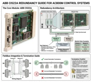
ABB CI522A Redundancy Guide for AC800M Control Systems
Technical Architecture and Communication Constraints
The internal design of the CI522A lacks dual-port circuitry or hot-standby capabilities. As a result, any failure in the module or the serial physical link causes an immediate communication loss. In critical sectors like oil and gas, this single-point failure poses a significant risk to data acquisition. Therefore, maintenance teams must prioritize external backup strategies. Industry reports suggest that while serial protocols remain relevant, their inherent lack of built-in redundancy drives the shift toward smarter gateways.
Integration with Redundant AC800M Controllers
While the module itself is non-redundant, you can utilize the CI522A within redundant PM861 or PM864 controller pairs. In this configuration, each controller hosts its own independent CI522A module. This setup maintains high availability at the controller level during a switchover. However, the field device must support dual communication paths to ensure a seamless transition. Many legacy Modbus RTU devices only allow one master, which creates a significant bottleneck in automated production lines.
Optimizing Protocol Redundancy via Modbus and Custom Serial
The CI522A primarily handles Modbus RTU and proprietary serial strings. Since Modbus RTU follows a strict master-slave architecture, achieving redundancy requires complex application-level logic. Moreover, any disruption in the master’s polling sequence can lead to device timeouts. As a result, many modern facilities deploy serial-to-Ethernet converters. This allows the system to leverage ABB’s Redundant Network Routing Protocol (RNRP) for much higher reliability than traditional serial links.
Installation Standards for High-Reliability Environments
Reliable operation starts with proper physical layer installation. Serial communication is notoriously sensitive to electromagnetic interference (EMI) and ground loops. To maintain signal integrity, follow these technical standards:
- ✅ Use high-quality shielded twisted-pair (STP) cables for all RS-485 runs.
- ✅ Ensure the cable shield is grounded at only one end to prevent loop currents.
- ✅ Implement isolated repeaters to segment long daisy chains and limit failure propagation.
- ✅ Install surge protection for any outdoor cable runs exceeding 50 meters.
Strategic Maintenance and Field Engineering Insights
From the perspective of Powergear X Automation Limited, we recommend treating the CI522A as a legacy bridge. While it is highly reliable for its intended purpose, it represents a “non-redundant edge” in your control system. If your project demands 99.99% uptime, consider migrating to Ethernet-based I/O. However, for retrofitting existing systems where downtime must be minimized, the CI522A remains a cost-effective solution for interfacing with localized analyzers and older PLCs.
Application Scenarios and Practical Solutions
- Chemical Processing: Use dual gateways to bridge CI522A serial data into the redundant Ethernet backbone of the AC800M.
- Power Plants: Distribute critical sensors across multiple CI522A modules to ensure that a single module failure does not blind the entire operator station.
- Water Treatment: Leverage the CI522A for non-critical monitoring while keeping core control on redundant Ethernet modules.
Frequently Asked Questions (FAQ)
Q: Can the AC800M firmware automatically switch between two CI522A modules if one fails?
No, the firmware does not perform an automatic “bumpless” switch for serial modules. You must write specific logic in Control Builder M to detect a “Module Error” and manually redirect communication tasks to a secondary module or port.
Q: Is the CI522A compatible with all versions of the PM866 controller?
The CI522A is compatible with most AC800M controllers, including the PM866. However, always verify that your specific firmware version supports the serial protocol you intend to use, as some older versions have library limitations for custom serial strings.
Q: How can I prevent data collisions when using two controllers with two CI522A modules?
The most effective way is to use a “Heartbeat” logic. Only the active controller should enable its CI522A communication block. If the backup controller takes over, it enables its communication port after a brief delay to ensure the serial bus is clear.
For high-quality modules and expert technical support for your control systems, visit the official Powergear X Automation Limited website to view our latest inventory.