Allen-Bradley 1769-OB32 Technical Guide: Features & Integration
Strategic Integration and Technical Analysis of the Allen-Bradley 1769-OB32 Digital Output Module
High-Density Control in Industrial Automation Ecosystems
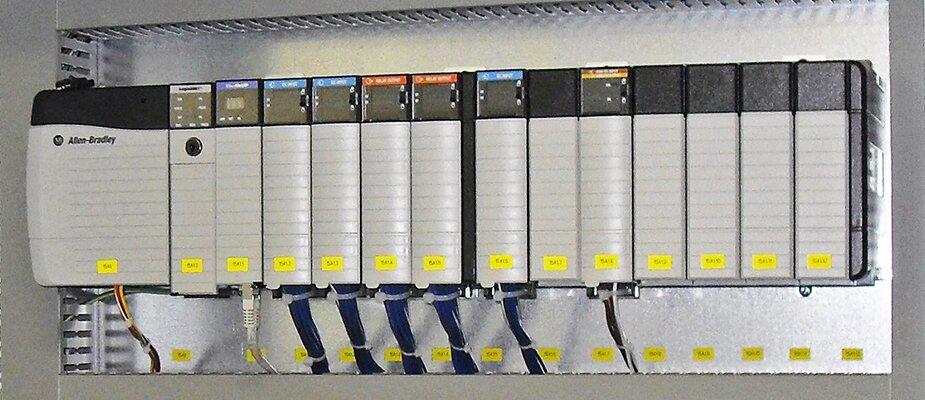
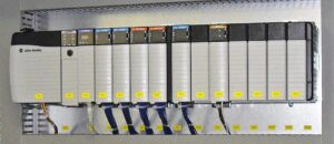
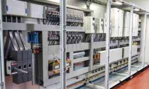
The Allen-Bradley 1769-OB32 stands as a high-density digital output solution within the Rockwell Automation CompactLogix family. This module provides 32 solid-state 24V DC sourcing outputs in a single compact slot. Consequently, it excels in factory automation environments where control cabinet space is at a premium. By consolidating multiple output points, engineers can drive relays, solenoids, and small actuators with maximum efficiency. However, its performance remains intrinsically linked to the Rockwell proprietary backplane architecture.
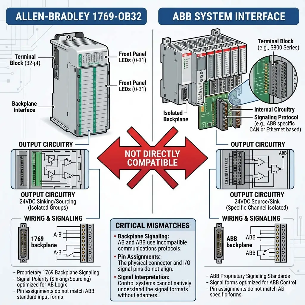
Why 1769-OB32 Is Not Directly Compatible with ABB Systems
Technical Mechanics: Sourcing Outputs and Backplane Dynamics
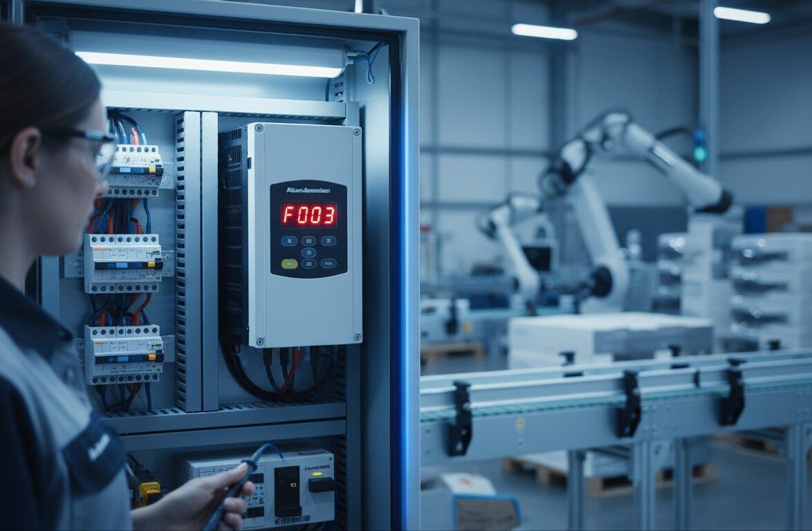
The 1769-OB32 utilizes a sourcing (PNP) logic configuration, which is the standard for North American industrial automation. Each output point delivers current to the field load, requiring a common ground for the circuit. In addition, the module features a typical response time of less than 1 millisecond. This speed is vital for high-speed packaging and sorting systems. Nevertheless, this hardware relies on the 1769 bus protocol for data exchange. This proprietary communication ensures sub-millisecond synchronization within a CompactLogix rack but creates a barrier for non-Rockwell systems.
Addressing Cross-Platform Compatibility Challenges
A frequent engineering query involves connecting the 1769-OB32 to ABB control systems like the AC500 or 800xA. In practice, direct physical integration is impossible due to incompatible backplane buses and communication protocols. While ABB might support EtherNet/IP, the physical 1769 interface is exclusive to Allen-Bradley. To bridge this gap, engineers often deploy industrial gateways (e.g., EtherNet/IP to PROFINET). However, this method introduces latency and increases system complexity. Therefore, Powergear X Automation Limited recommends using native ABB I/O modules for ABB-centric projects to ensure long-term stability.
Installation Standards and Maintenance Best Practices
Field experience suggests that proper protection is essential for maximizing the lifespan of the 1769-OB32. Inductive loads, such as large solenoids, can generate significant back-EMF during switching. To mitigate this risk, follow these technical guidelines:
- ✅ Surge Suppression: Install flyback diodes or RC snubbers across inductive loads to prevent output point damage.
- ✅ Grounding Protocols: Use shielded cables for long-distance runs and implement single-point grounding to reduce EMI.
- ✅ Power Quality: Deploy 24V DC surge protective devices (SPD) in environments prone to lightning or heavy motor interference.
- ✅ Wiring Integrity: Ensure the 18-point removable terminal block (RTB) is securely seated to avoid intermittent connectivity.
Strategic Procurement: Assessing Total Cost of Ownership
From a buyer’s perspective, the 1769-OB32 is a high-value asset primarily when maintaining an existing Rockwell infrastructure. According to MarketsandMarkets, the global PLC market is shifting toward unified ecosystems to reduce downtime. Mixing I/O brands often leads to “hidden costs” in the form of specialized spare parts and extended troubleshooting hours. If your primary DCS is ABB, replacing 1769 modules with native S500 or S800 series I/O is usually the more cost-effective strategy over the machine’s lifecycle.
Expert Commentary from Powergear X Automation Limited
At Powergear X Automation Limited, we emphasize that the 1769-OB32 is a specialized component, not a generic universal tool. It represents the pinnacle of compact sourcing output technology for the CompactLogix range. While communication integration via gateways is technically feasible, it is rarely the most “elegant” engineering solution. We advise our clients to prioritize platform homogeneity. This approach minimizes “MTTR” (Mean Time To Repair) and simplifies the training requirements for plant floor technicians.
Application Scenarios and Practical Solutions
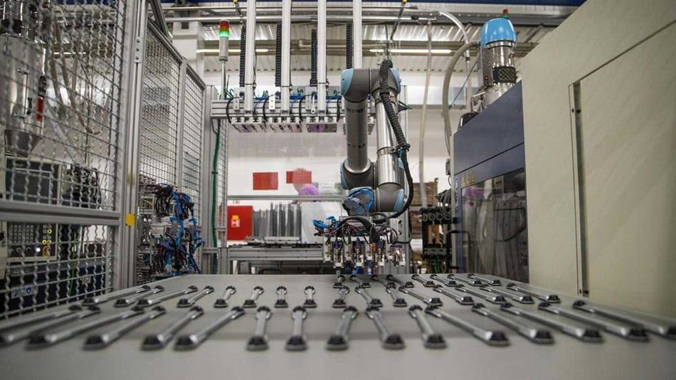
- Automotive Assembly: Managing 32-point valve banks for pneumatic clamping systems in high-speed robot cells.
- Discrete Manufacturing: Controlling small DC motor starters and signal indicators in compact control panels.
- Legacy Migrations: Acting as a high-density replacement during upgrades of older SLC 500 systems to CompactLogix.
Frequently Asked Questions (FAQ)
Q: Can I mix NPN sensors with the 1769-OB32 sourcing outputs?
Direct connection is not possible because the 1769-OB32 provides current (PNP) while NPN sensors expect a sinking input. You must use intermediate relays or signal converters to bridge the two different logic types.
Q: What is the primary cause of individual output point failure on this module?
The most common cause is an overcurrent condition or a short circuit in the field wiring. Since these are solid-state outputs, a single high-voltage spike from an unprotected solenoid can permanently damage the switching transistor for that specific channel.
Q: Is it better to use a gateway or replace the module when switching to an ABB controller?
Unless the 1769-OB32 is part of a large, pre-existing rack that cannot be moved, replacing it with native ABB I/O is the superior choice. Gateways add a “point of failure” and increase communication jitter, which can affect precision timing.
To discover more high-performance modules and expert automation advice, please visit the official Powergear X Automation Limited website for our latest inventory and technical support.