Over 50,000 hot-selling automation module components.

Troubleshoot Bently Nevada 3300 XL System Errors

Troubleshooting Bently Nevada 3500 Bypass and Not OK Faults in 3300 XL Systems

Industrial plants rely heavily on the Bently Nevada 3500 Monitoring System to protect critical rotating machinery. However, maintenance teams frequently encounter yellow Bypass or red Not OK indicators on channel modules. These alarms disrupt operations and threaten plant safety. Our team at Powergear X Automation observes that many operators immediately blame the hardware probe. In reality, issues often stem from simple wiring faults or improper installation gaps.

This technical guide provides a systematic process to isolate faults within your Bently Nevada 3300 XL Proximity Transducer System. Following these steps helps engineers prevent costly false shutdowns. Furthermore, it ensures your machinery asset protection platform operates reliably.

Understanding the Core Value of Proximity System Data

Continuous vibration monitoring safeguards high-capital assets like steam turbines, centrifugal compressors, and large electric motors. The Bently Nevada 3300 XL system utilizes eddy current principles to measure shaft vibration and axial displacement. According to API 670 standards, machinery protection systems must deliver maximum uptime and accurate fault metrics.

When a 3500 monitor registers an alert, the entire data loop requires inspection. Data collected by Powergear X Automation indicates that over 60% of proximity probe errors originate from loose physical connections. Therefore, field technicians should analyze the complete loop before ordering expensive replacement parts.

Decoding Gap Voltage as Your Primary Diagnostic Metric

The 3300 XL Proximitor Sensor outputs a negative DC voltage proportional to the distance between the probe tip and the target shaft. Under normal operating conditions, a calibrated system maintains a static gap voltage near -8.0 VDC. This value represents the midpoint of the linear range for standard 8mm eddy current transducers.

Technicians must use a digital multimeter to measure this voltage directly at the Proximitor terminal block. If the reading approaches 0 VDC, a short circuit or physical contact likely occurred. Conversely, an over-scale reading near -24 VDC indicates an open circuit or an excessive physical gap. Always verify these voltages before adjusting any mechanical bracket.

Verifying Component Compatibility and Configuration Parameters

System mismatch frequently triggers a persistent Not OK alarm on the 3500 rack. Every eddy current measurement loop requires precise calibration between the probe, extension cable, and sensor. For example, a 5-meter Proximitor sensor will not function accurately with a 9-meter cable length.

Moreover, the 3500 configuration software must match the physical hardware profile exactly. If an engineer replaces an older sensor with a 3300 XL 8mm probe without updating the scale factor, the monitor rejects the signal. Always verify the scale factor, which typically equals 200 mV/mil (7.87 V/mm) for standard applications.

Differentiating Channel Logic Between Bypass and Not OK Alerts

Engineers must carefully distinguish between the structural meanings of yellow and red status lights. A yellow Bypass light indicates that a user or automated logic has manually suppressed the channel alerts. Consequently, the monitor does not execute automatic trip functions for that specific transducer.

A red Not OK light signifies a severe hardware or signal transmission failure. The internal diagnostics of the 3500 monitor have detected a fault that compromises data integrity. The table below outlines the primary culprits behind these critical errors.

Fault LocationTypical Symptom ObservedRoot Cause Category
3300 XL ProbeErratic gap voltage readingsMechanical damage or physical contamination
Extension CableIntermittent Not OK alarmsLoose coaxial connectors or internal conductor breaks
Proximitor SensorZero voltage output on terminalInternal circuit failure or loss of -24VDC power
3500 Input ModuleSingle isolated channel failureBackplane interface damage or configuration error

Executing the Step-by-Step Loop Inspection Sequence

To safely isolate a fault without disturbing adjacent channels, maintain a strict diagnostic sequence. Technicians should systematically move from the monitoring instrument down to the physical machine environment.

  1. Check the 3500 Rack Status: Review the event logs via the configuration software to identify the exact error timestamp.
  2. Measure Power Supply Voltages: Confirm the Proximitor sensor receives a stable -24 VDC input from the rack terminal.
  3. Inspect the Coaxial Connectors: Ensure the miniature gold ClickLoc connectors between the probe and extension cable are clean and insulated.
  4. Perform Cross-Channel Validation: Swap the suspect channel input with a known functional channel on the same 3500 module.

If the fault moves to the new channel during validation, the issue lies in the field components. However, if the fault stays on the original channel, the 3500 module requires replacement or reconfiguration.

Optimizing the Installation Environment for Signal Stability

Harsh industrial environments introduce significant physical stress to delicate monitoring cables. High-vibration machinery can cause micro-abrasions in extension cables if they lack flexible armor conduit protection. In addition, routing signal lines parallel to high-voltage motor power cables introduces electrical noise.

Always ground the extension cable shield at the 3500 rack end only. Floating or double-grounded shields create ground loops that distort critical vibration metrics. For outdoor installations, ensure that all terminal junction boxes maintain their NEMA 4X weatherproofing integrity.

Industry Insights from Powergear X Automation

We observe that procurement managers often waste budget by immediately purchasing new probes during an outage. Proximity probes are highly durable components because they feature no moving parts. Most failures stem from oil ingress inside the cable connectors or cracked ceramic tips caused by incorrect installation depth.

We recommend keeping a small stock of matched 3300 XL Proximitor sensors and extension cables instead of excessive probe bodies. This strategy minimizes inventory costs while addressing the most common failure points in factory automation ecosystems.

Real-World Application Scenario

At a large petrochemical plant, a centrifugal compressor feed pump triggered a sudden red Not OK alarm on its radial vibration channel. The operator prepared to halt production to replace the sensor body. However, the maintenance engineer utilized a multimeter to check the terminal block. The engineer discovered a gap voltage of -23.5 VDC. Instead of pulling the probe, they inspected the junction box and found a disconnected extension cable nut. Tightening the connector restored the -8.0 VDC gap and cleared the system alarm within ten minutes, saving thousands of dollars in potential downtime.

Frequently Asked Questions

Q1: Can I mix 5-meter and 9-meter 3300 XL system components?
No. The total electrical length of the probe plus the extension cable must match the specific calibration of the Proximitor sensor. Mixing lengths changes the system impedance and ruins the measurement linearity.

Q2: What is the fastest way to clear a false Bypass status?
Connect your computer to the 3500 rack via the configuration software. Navigate to the channel status window, verify the physical sensor loop is stable, and deselect the “Bypass” option before downloading the changes to the rack.

Q3: How often should we calibrate the 3300 XL proximity loop?
Industry standards recommend verifying the calibration curve every 12 to 24 months during planned machinery turnarounds. Use a specialized spindle micrometer to check voltage changes across the entire linear range.

Need to replenish your critical plant machinery protection spares? Discover an extensive inventory of authentic control systems components and components by visiting Powergear X Automation to secure your facility’s operational uptime today.

Does a Failed S800 DO630 Module Disrupt ModuleBus Communication?

Does a Damaged DO630 Module in the First Slot Halt Downstream S800 I/O Communication?

Field engineers frequently encounter hardware failures in distributed control systems. A common concern involves the ABB S800 I/O system via a CI801 PROFIBUS DP interface (part number 3BSE022366R1). Specifically, professionals ask whether an electrical failure on the first DO630 digital output module disrupts communication to subsequent I/O modules on the same cluster. Powergear X Automation leverages extensive field experience to analyze this critical hardware diagnostic scenario.

Understanding S800 ModuleBus Architecture and Data Routing

The short answer is no, a standard electrical failure on a single DO630 module will not block communication to downstream modules. Unlike traditional serial daisy-chain networks, the ABB S800 I/O system utilizes a parallel backplane topology known as ModuleBus. The CI801 interface module communicates directly with each local I/O slot through this shared parallel bus. Therefore, individual I/O modules do not act as data repeaters for the next unit in line. If the first DO630 module fails due to an isolated channel issue, the remaining AI, AO, DI, and DO modules continue to refresh their process variables normally.

How Isolated Power Circuits Protect Factory Automation Networks

Electrical isolation plays a vital role in protecting modern programmable logic controllers (PLC) and distributed control systems (DCS). The DO630 digital output module features strict separation between its internal ModuleBus communication electronics and the external 24VDC field load power. Industry statistics indicate that over 70% of digital output failures stem from severe field-side anomalies. These field issues include shorted solenoid valves, inductive voltage surges from contactors, and improper field wiring. Because of this robust optical isolation, field-side electrical overstress rarely penetrates the internal ModuleBus logic circuit, ensuring overall network stability.

When a Local Module Fault Escalates to a System-Wide Outage

However, automation technicians must not rule out severe cascading failures entirely. While data routing is parallel, severe physical damage can occasionally bridge the isolation barriers. For instance, a catastrophic overvoltage event might physically scorch the module substrate. As a result, the damaged circuit might drag down the shared ModuleBus 5VDC logic power supply. Moreover, a bent pin on the MTU (Module Termination Unit) baseplate during hot-swapping can cause a physical short circuit across the data lines. Consequently, the entire CI801 cluster will drop offline, rendering all downstream I/O unreadable.

Proven Field Inspection Guidelines for Automation Engineers

When troubleshooting a suspected I/O cluster failure, engineers should follow a structured diagnostic sequence rather than relying on guesswork:

  • Verify LEDs: Check the RUN and FAULT LED indicators on both the CI801 interface and individual I/O modules.
  • Monitor Software: Review the Control Builder diagnostic buffer for specific “ModuleBus Error” or “Module Missing” flags.
  • Measure Voltages: Measure the logic power lines and the external 24VDC field distribution voltages separately.
  • Inspect Hardware: Examine the MTU backplane connectors for physical alignment, debris, or thermal damage.

Proactive Suppression Strategies to Reduce Hardware Failure Rates

Industrial standards like IEC 61131-2 define rigorous boundaries for PLC input and output voltage tolerances. To minimize DO630 component degradation from inductive load switching, plants should implement reliable external suppression. Technicians should always install freewheeling diodes across heavy DC inductive loads. Similarly, installing RC snubbers across AC contactors effectively dampens transient voltage spikes. Implementing these engineering best practices drastically mitigates the risk of catastrophic failures that could disrupt the entire ModuleBus segment.

Real-World Application Scenario and Solution

In a continuous chemical processing plant, a 24VDC solenoid valve coil failed shut, causing a direct short circuit on the first DO630 module of a remote I/O station. Thanks to the S800 parallel ModuleBus design, the adjacent AI810 analog input modules continued transmitting critical temperature and pressure data to the main AC 800M controller. The plant operator safely scheduled a targeted, hot-swapping maintenance window during a shift change. Maintenance personnel replaced the faulty DO630 module without shutting down the primary production line, proving the high availability of the system.

Expert Insights from Powergear X Automation

Modern industrial automation prioritizes system availability and rapid fault isolation. When diagnosing S800 infrastructure, a single module fault should never justify an immediate, costly replacement of the main communication adapter. For reliable sourcing of original industrial components, technical documentation, and expert engineering support, visit Powergear X Automation to optimize your plant maintenance strategies.

Frequently Asked Questions

Q1: Can I hot-swap a failed DO630 module while the CI801 station is actively running?
Yes. The ABB S800 I/O platform supports hot-swapping (Removal and Insertion Under Power) when using appropriate MTU bases. However, you must insert the new module straight into the slot to prevent bending the ModuleBus connector pins.

Q2: What specific diagnostic code indicates a backplane communication breakdown rather than a single module failure?
A single module failure typically triggers a “Module Fault” or “Channel Error” in the controller hardware tree. Conversely, a total backplane issue will trigger a continuous “ModuleBus Error” or report all subsequent slots as “Module Missing”.

Q3: How do I isolate whether a fault originates within the DO630 module or the underlying MTU baseplate?
First, move the suspected DO630 module to an empty, identically configured slot on a known working cluster. If the fault follows the module, the module is defective. If the fault remains at the original slot with a new module, inspect the MTU baseplate and its underlying ModuleBus connection.

How to Power Photoelectric Keyphasor via Bently Nevada 3500/40M

How Does the Bently Nevada 3500/40M Keyphasor Module Supply 15VDC Power to a Photoelectric Sensor?

Understanding the Role of Keyphasor Modules in Factory Automation

Reliable machinery protection systems form the backbone of modern industrial automation. Within these setups, the Bently Nevada 3500/40M Proximity Keyphasor Module plays a critical role. It captures essential shaft reference signals for rotational speed measurement, phase analysis, and critical vibration diagnostics.

When engineers select a photoelectric sensor as the primary input device, commissioning often brings up a practical engineering challenge. Technicians frequently wonder if the 3500/40M Rear I/O module can directly supply the required 15VDC operating power. Powergear X Automation presents this comprehensive technical guide to clarify wiring configurations, electrical compatibility, and best practices for the field.

Analyzing the Core Engineering Value for Critical Machinery

The 3500/40M Keyphasor system generates a vital once-per-revolution pulse to synchronize vibration data across the entire PLC and DCS infrastructure. Without an accurate reference pulse, advanced diagnostics like orbit analysis, shaft centerlines, and rotor balancing calculations fail.

Industrial facilities in the oil & gas, petrochemical, and power generation sectors rely on these continuous data streams. According to EPRI (Electric Power Research Institute) reliability statistics, improper instrumentation accounts for over 30% of false machinery trips. Utilizing the internal 15VDC supply simplifies field installations. Consequently, this design choice eliminates external power supplies and significantly reduces complex cable routing.

Technical Deep Dive: The 15VDC Excitation Circuit and Signal Integrity

The standard internal circuitry of specific 3500/40M Rear I/O modules includes a regulated excitation voltage output. This hardware path routes a steady 15VDC directly to the designated sensor power terminal blocks.

  • Component Redundancy: Direct wiring removes independent external power supplies, which reduces the total bill of materials (BOM).
  • Ground Isolation: Utilizing the internal power loop minimizes the risk of ground loops between the machinery skid and the control cabinet.
  • Design Simplification: Fewer active devices inside the marshalling panel streamline future maintenance tasks.

However, field engineers must verify the exact bill-of-materials part number before wiring. Certain legacy hardware revisions or specific isolated I/O variants alter this standard power distribution model.

Evaluating Sensor Output Formats and Digital Compatibility

Photoelectric sensors commonly feature diverse electronic output stages. These variants typically include open-collector, NPN, PNP, or TTL pulse outputs. The Bently Nevada 3500/40M module requires highly precise voltage thresholds and sharp edge transitions to register a valid event.

Sensor Output TypeCompatibility with 3500/40MRequired Action / Engineering Verification
NPN Open-CollectorFully CompatibleRequires correct pull-up resistor configuration via internal jumpers.
PNP Voltage PulseCompatibleMatch peak voltage limits with the module’s input thresholds.
TTL Level (5V)Moderately CompatibleVerify threshold settings within the 3500 Rack Configuration Software.

An incompatible configuration can lead to missing pulses or corrupted speed readings. Therefore, engineers must match sensor electrical data sheets with the monitoring system specifications rather than assuming universal interoperability.

Optimizing Pulse Response Times for High-Speed Turbomachinery

The Keyphasor card monitors rapid pulse edge transitions rather than smooth, continuous analog voltage variations. As a result, the switching frequency and response time of your photoelectric sensor directly dictate system accuracy.

In high-speed applications like gas turbines or centrifugal compressors, sluggish sensor response times cause phase jitter. This timing drift severely distorts balancing routines. Powergear X Automation recommends industrial-grade optical sensors with high ambient light rejection and microsecond response times. This step ensures consistent tracking during transient machine conditions, such as rapid startups or emergency trips.

Step-by-Step Commissioning and Field Installation Guide

Engineers must adhere to precise electrical checks during initial commissioning to ensure long-term system reliability.

  1. Verify the Current Budget: Confirm that the current draw of the photoelectric sensor does not exceed the maximum mA rating of the Rear I/O module.
  2. Configure Module Jumpers: Open the module housing to set internal jumpers for the correct input signal type (e.g., Proximitor or Magnetic Picker/Digital).
  3. Terminate Power Connections: Wire the sensor positive lead to the +15VDC terminal and the common lead to the COM terminal on the Rear I/O connector block.
  4. Connect Signal Channels: Land the sensor pulse output line on the dedicated SIG terminal of the respective Keyphasor channel.
  5. Verify the Waveform: Use an oscilloscope to inspect the pulse wave shape directly at the rack terminals while the machine rotates.

Mitigating Noise Interference via Grounding and Shielding Protocols

Machinery skids often generate significant electromagnetic interference (EMI) due to nearby variable frequency drives (VFDs) and high-power motor leads. Field experience indicates that poor shielding causes most intermittent Keyphasor failures.

  • Always use high-quality twisted, shielded instrument cables for all field runs.
  • Terminate the cable shield only at the 3500 rack ground bar to prevent dangerous ground loops.
  • Keep signal lines isolated from high-voltage AC power trays by maintaining at least 12 inches of physical separation.

Following these clean-wiring principles prevents unwanted electrical noise from triggering false speed readings or unexpected system shutdowns.

Protecting Outdoor Infrastructure Against Surge Transients

Photoelectric hardware mounted on outdoor cooling towers or exposed offshore skids faces continuous risk from lightning and surge transients. Industrial plants can prevent costly module damage by integrating specific physical protections.

  • Install dedicated DIN-rail surge protection devices (SPDs) inside local field junction boxes.
  • Ensure the metal sensor housing maintains a low-resistance path to the local machine skid ground.
  • Implement heavy-duty, weather-proof conduits to protect field cables from physical deterioration and ultraviolet exposure.

These rugged installation practices extend component life cycles and preserve data continuity across harsh operational environments.

Industrial Application Scenario: Centrifugal Compressor Retrofit

Consider a large-scale chemical facility retrofitting an older centrifugal compressor train. The engineering team replaced an obsolete magnetic pickup with a modern high-speed photoelectric sensor to track low-speed start-up conditions more effectively.

By utilizing the internal 15VDC supply from the Bently Nevada 3500/40M Rear I/O card, the plant eliminated two external power units per panel. The system successfully integrated with the main plant Distributed Control System (DCS) via Modbus TCP. Consequently, this layout provided the reliability required for critical machine interlocks. The upgrade delivered precise phase accuracy, allowing the plant to execute accurate dynamic balancing procedures.

Industry FAQs: Keyphasor Power and Configuration

Q1: Can I power two photoelectric sensors from a single 3500/40M Keyphasor channel terminal?

A: No. Each terminal possesses a strict current limitation designed for one sensor. Overloading the circuit can trigger internal current-limiting protection or damage the module card.

Q2: What happens if the photoelectric sensor voltage requirement is 24VDC instead of 15VDC?

A: The sensor will likely fail to power up or may operate erratically. In this scenario, you must deploy an external 24VDC industrial power supply and route the signal common correctly.

Q3: How do I adjust the threshold voltage if the sensor pulse is too weak?

A: You can adjust the threshold and hysteresis settings through the 3500 Rack Configuration Software under the Keyphasor options tab.

Power Up Your Industrial Automation Systems with Confidence

Selecting the right components and understanding precise electrical wiring saves significant commissioning time and avoids unexpected downtime. If you are upgrading your machinery protection systems or expanding your facility’s control capabilities, sourcing genuine, reliable components is vital. Discover high-quality industrial control hardware, specialized modules, and expert technical support by visiting Powergear X Automation today.

Troubleshooting PM802F Redundancy Failure | Powergear X

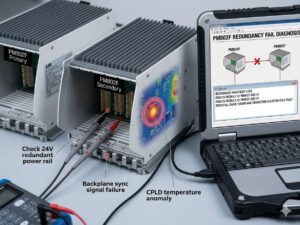
Resolving PM802F Redundancy Switching Failure: Online Diagnostics for Dual Channel Errors

Understanding the Dual Channel Error Crisis

In ABB Freelance distributed control systems (DCS), the PM802F controller manages critical process loops. However, field engineers occasionally face a catastrophic simultaneous Channel Error alarm on both the primary and backup central processing units (CPUs) during a redundancy switchover. This specific failure can halt production in continuous-process industries like petrochemical, fine chemical, and pharmaceutical manufacturing. Industrial automation professionals often assume a hardware defect caused the fault. Nevertheless, field data reveals that pure hardware failure accounts for less than fifteen percent of these incidents. Most issues stem from complex synchronization disruptions, fiber optic instability, firmware mismatches, or unbalanced controller loading.

The Mechanics of Redundancy Synchronization States

The redundancy mechanism relies on constant data mirroring between the active and standby units to ensure seamless hot-standby switching. Engineers must monitor the real-time synchronization status through Freelance Engineering diagnostics before initiating any maintenance. The system exhibits several distinct operational states during runtime. A Synchronized status indicates a complete data mirror, making it safe for manual or automatic switchover. Conversely, a Synchronizing state points to an ongoing initial data transfer, which introduces significant switching risks. If the system displays Not Synchronized, the runtime data between the two units is mismatched, rendering the redundancy completely invalid.

Root Causes of Interrupted Synchronization Channels

When both controllers report a Channel Error concurrently, the physical and logical communication link has failed. Technicians frequently discover reversed transmit (TX) and receive (RX) fiber lines during commissioning or post-maintenance startups. Moreover, microscopic physical contamination inside ST fiber connectors increases optical attenuation beyond acceptable limits. In large-scale factory automation projects, excessive CPU utilization can trigger synchronization timeouts. If the primary controller scan rate exceeds eighty percent during a major online application download, it may fail to update its partner within the designated time window. This timeout forces both units into an isolated error state.

Analyzing Firmware and Control Project Consistency

A frequent error during emergency maintenance involves replacing only one damaged controller while leaving the older partner online. ABB Freelance architecture requires absolute consistency across the redundant pair to maintain stable operations. System synchronization will fail if the firmware revisions do not match perfectly. Furthermore, any discrepancy in the Control Builder project cyclic redundancy check (CRC) checksum prevents successful data mirroring. Inconsistent Fieldbus Foundation High-Speed Ethernet (FF/HSE) communication objects or outdated I/O topology definitions also disrupt the background synchronization process. Consequently, the backup controller may remain trapped in a permanent Synchronizing loop.

Evaluating Redundancy Link Communication Quality

Healthy link light-emitting diodes (LEDs) on the controller faceplate do not guarantee flawless data transmission. Intermittent optical degradation often hides behind solid green indicators, causing random switching failures during load transitions. High electromagnetic interference (EMI) environments, such as compressor stations or variable frequency drive (VFD) cabinets, severely impact communication quality if fiber cables run parallel to high-voltage lines. Engineers must track specific health metrics to predict failures before they disrupt operations.

  • Optical Attenuation: Fluctuations greater than 3 dB indicate dirty connectors or excessive cable bending.
  • Redundancy Latency: An increasing latency trend indicates packet loss and imminent timeout alarms.
  • CRC Communication Errors: Continuous increments reveal electrical noise or failing transceiver modules.
  • CPU Utilization: Sustained loading above 80% delays the critical redundancy background tasks.

Online Inspection and Maintenance Protocols

Engineers must follow a strict diagnostic sequence before physically removing any hardware from the rack. First, open the Freelance Engineering diagnostics console to verify the active and standby assignments. Second, confirm that the synchronization counter is updating steadily. Never extract a suspected backup CPU while the synchronization process is incomplete, because this action can force the primary controller into a standalone degraded mode. If a channel error exists, avoid repeated forced role switching or simultaneous reboots, as these actions corrupt the runtime redundancy buffers. Stabilize the communication medium first, allow one controller to establish a firm primary role, and let the system rebuild synchronization gradually.

Expert Insights from Powergear X Automation Limited

As industrial control systems age, lifecycle management becomes crucial for plant reliability. Our engineering team at Powergear X Automation Limited notes that mixed-generation hardware and firmware variants cause over sixty percent of chronic synchronization issues. When migrating older Freelance systems, users must strictly validate the compatibility matrix for control software, CI modules, and Ethernet topologies. Replacing individual components without checking project CRCs often introduces hidden vulnerabilities. We highly recommend executing a comprehensive digital diagnostic audit before scheduling hardware upgrades during planned turnarounds.

Industrial Application and Solution Scenario

Consider a large refinery utilizing redundant controllers to manage a critical distillation column interlock system. During a routine maintenance window, the secondary controller suddenly lost its connection, and both units flagged a dual channel error. Instead of replacing the expensive CPU modules immediately, the instrument team checked the diagnostic logs. The event log showed a continuous increment in CRC communication errors, coinciding with the startup of a nearby heavy-duty cooling pump. Technicians rerouted the fiber optic cables into a shielded conduit and cleaned the ST connectors with isopropyl alcohol. The optical attenuation dropped by 4 dB, the synchronization state returned to Synchronized within minutes, and the plant avoided an unscheduled shutdown scenario.

Frequently Asked Questions

How do you differentiate between a physical fiber fault and a software logic conflict when troubleshooting redundancy errors?
Look directly at the error counters in the engineering tool. A physical fault causes a steady rise in CRC errors and sudden link drops, whereas a logic conflict allows the link to stay active while keeping the backup unit stuck in a continuous synchronizing loop with mismatched project checksums.

What specific field tools are necessary to validate the synchronization channel without interrupting live operations?
Engineers should use the internal Freelance Diagnostics software tool to read live buffer states and counter trends online. For physical validation, an optical power meter can measure line attenuation at the patch panel without disconnecting the active online controller.

Why does an online project download occasionally break the synchronization link on healthy controller pairs?
When a project download contains massive structural changes or expanded I/O topologies, the primary unit requires extra processing power to compile the changes. If the base CPU utilization is already high, this extra load delays the synchronization heartbeat packets, causing the backup unit to declare a timeout fault.

For more technical documentation, original spare parts, and advanced system integration support, please visit the official website of Powergear X Automation Limited to consult with our certified application engineers.

Universal I/O Integration: Honeywell CC-PUIO31 on CC-TUIO01

Universal I/O Integration: Honeywell CC-PUIO31 on CC-TUIO01

Optimizing Honeywell Experion Systems with CC-PUIO31 and CC-TUIO01 Integration

The Honeywell CC-PUIO31 module installs directly onto the CC-TUIO01 baseplate. This hardware pairing delivers a sophisticated Universal I/O solution for modern industrial environments. However, achieving peak performance requires more than a physical connection. Engineers must evaluate system release levels, power distribution, and grounding strategies. Success depends on aligning these technical variables with Honeywell’s specific Universal I/O standards.

Universal I/O Integration: Honeywell CC-PUIO31 on CC-TUIO01

The Versatility of Universal I/O Architecture

The combination of CC-TUIO01 and CC-PUIO31 introduces software-defined I/O to the Honeywell Experion platform. This technology allows a single hardware channel to function as AI, AO, DI, or DO. Consequently, engineers can reconfigure channels through software without changing physical wiring. This flexibility significantly reduces engineering risks during late-stage project modifications. Furthermore, it minimizes the need for extensive spare parts inventory in large-scale plants.

Critical Hardware Compatibility and Power Management

The CC-TUIO01 baseplate serves as the essential mechanical and electrical interface for the CC-PUIO31 module. While they fit together perfectly, the CC-PUIO31 demands more power than traditional fixed-function modules. Therefore, you must verify your 24 VDC field power supply capacity before installation. Undersized power supplies often lead to intermittent channel failures rather than total system shutouts. Adequate power sizing ensures long-term stability in demanding process environments.

Software Dependencies and Firmware Requirements

Functionality relies heavily on the Experion PKS system release and firmware versions. Typically, CC-PUIO31 requires Experion R430, R431, or later versions to operate correctly. Although the hardware may physically mount on older systems, the software might not recognize the Universal I/O capabilities. As a result, users could face commissioning delays or unexpected upgrade costs. Always cross-reference the Honeywell firmware compatibility matrix before beginning a brownfield project.

Best Practices for Reliable Industrial Installation

Professional installation determines the reliability of your control system in harsh conditions. Even though channels are software-defined, smart physical planning remains necessary. For instance, you should avoid placing low-level analog signals next to high-frequency digital lines. In addition, always utilize single-point grounding at the control cabinet to prevent signal interference. Properly terminated shield drains at the terminal base prevent the 4–20 mA instability common in industrial sites.

Powergear X Automation Expert Insights

At Powergear X Automation, we observe that Universal I/O technology represents the future of DCS flexibility. We recommend that engineers perform a thermal cycle check after the initial startup. Tightening terminal screws after the first heating cycle prevents micro-loosening in high-vibration areas like compressor skids. This simple maintenance step eliminates hard-to-diagnose intermittent alarms. For high-quality components and expert support, visit Powergear X Automation to explore our comprehensive hardware solutions.

Technical Summary Checklist

  • Verify System Version: Ensure Experion PKS is at R430 or higher.
  • Power Calculation: Confirm 24 VDC field power supports higher PUIO demand.
  • Wiring Integrity: Use ferrules and maintain proper grounding.
  • ⚙️ Channel Mapping: Plan signal types in software before commissioning.
  • 🔧 Maintenance: Re-torque terminals after the system reaches operating temperature.

Application Scenario: Brownfield Plant Revamp

A major chemical refinery recently transitioned from fixed I/O to the CC-PUIO31 and CC-TUIO01 architecture. During the final commissioning phase, the team discovered several instruments required different signal types than originally planned. Because they used Universal I/O, the engineers changed the channel configurations in the software within minutes. This eliminated the need for cabinet rewiring and saved the project approximately three weeks of labor.

Frequently Asked Questions (FAQ)

1. Can I use the CC-TUIO01 baseplate with traditional AI or DI modules?
No, the CC-TUIO01 is designed exclusively for Universal I/O modules like the CC-PUIO31. Traditional fixed-function modules require their own specific terminal assemblies.

2. What happens if I install CC-PUIO31 on an older Experion release?
The module might power up, but the system will likely fail to configure the universal channels. You will lack the software interface needed to define the I/O types.

3. Why is grounding so critical for the CC-PUIO31?
The high-density nature of 30 universal channels makes the module sensitive to electromagnetic interference. Proper grounding ensures signal integrity for sensitive 4–20 mA loops.

For more information on optimizing your control system hardware, discover the latest products at Powergear X Automation.

Choosing BN 3500 Modules for Industrial Vibration Monitoring

Choosing BN 3500 Modules for Industrial Vibration Monitoring

Choosing the Right Bently Nevada Monitor: 3500/40M vs. 3500/42M for Industrial Automation

Selecting the optimal machinery protection module is vital for system reliability in industrial automation environments. Bently Nevada’s 3500 series offers two primary choices for vibration monitoring: the 3500/40M Proximitor® Monitor and the 3500/42M Proximitor®/Seismic Monitor. Although both are cornerstones of a robust control systems setup, their capabilities and ideal applications differ significantly. Understanding these distinctions ensures you select the best fit for your factory automation needs.

Choosing BN 3500 Modules for Industrial Vibration Monitoring

The Specialized Focus of the 3500/40M Proximitor Monitor

The 3500/40M, a four-channel monitor, maintains a precise and focused application scope. It exclusively manages input from proximity probes (Proximitors). This design targets machines where shaft movement relative to the bearings or housing is the most critical measurement. We primarily see the 40M utilized in high-speed turbomachinery, such as steam and gas turbines, or critical large compressors. It excels at measuring:

  • Shaft Relative Vibration: Detecting radial movement of the rotating shaft.
  • Shaft Position: Monitoring axial (thrust) position.
  • Keyphasor Signals: Providing critical phase reference for diagnostic analysis.

This module is a gold standard where the protection strategy hinges entirely on relative shaft vibration measurements, a common practice in API 670 compliance for critical assets.

Expanded Versatility with the 3500/42M Proximitor/Seismic Monitor

The 3500/42M offers a much broader set of features, reflecting its dual-purpose design. It is also a four-channel module, but its key differentiator is the flexibility in sensor input. The 42M accepts not only proximity probes but also seismic sensors. This makes it suitable for equipment requiring both shaft and casing vibration monitoring simultaneously.

The 42M can measure:

  • Shaft Relative Vibration and Position (using Proximitors).
  • Casing Absolute Vibration (using velocity or acceleration transducers).

Therefore, the 42M module is a preferred choice for monitoring “balance-of-plant” equipment. This includes motors, pumps, fans, and gearboxes, assets that often require casing vibration monitoring for condition assessment. Moreover, the ability to mix sensor types within a single module significantly simplifies the PLC or DCS I/O integration.

Key Technical Differences: Sensor Compatibility and Measurement Scope

The primary technical divergence lies in the sensor compatibility, which directly dictates the module’s application scope.

  • The 3500/40M is limited to Proximitor inputs. Consequently, its measurements are inherently relative to the sensor mount.
  • However, the 3500/42M supports a mixed configuration. It handles Proximitor, seismic velocity, and seismic acceleration sensors.

This flexibility allows the 42M to deliver both relative (shaft) and absolute (casing) vibration readings, providing a more comprehensive view of machine health. In addition, the 42M’s advanced signal processing adapts easily to the different dynamics of various sensor types, offering a more versatile tool for maintenance engineers.

Application Scenarios: Turbomachinery vs. General-Purpose Machinery

The selection between the 40M and 42M often comes down to the machinery type and criticality.

  • 3500/40M for Critical Turbomachinery: When monitoring large, critical assets like turbines or hydrogen compressors, the protection philosophy focuses on preventing contact between the shaft and stationary parts. The 40M provides the precise, dedicated proximity measurements needed.
  • 3500/42M for Flexible Monitoring: For general-purpose machinery, such as an ANSI pump or a cooling tower fan, casing vibration provides sufficient data for condition monitoring. The 42M offers an economical, multi-sensor solution for these assets, consolidating diverse inputs into one industrial automation rack.

Author’s Insight: From a system design perspective, I believe the 42M offers superior long-term value in an expanding plant. While the 40M is perfect for pure API 670 compliance on a turbine, the 42M is far more future-proof. It allows the plant to easily integrate new sensor types (like accelerometers for gearbox fault detection) without adding an entirely new monitoring chassis.

Choosing the Right Module: A Practical Decision Matrix

Consider these practical points before making your final selection:

Choose the 3500/40M if:

  • Your equipment is critical, high-speed turbomachinery.
  • You require pure proximity measurements (shaft vibration, thrust).
  • API 670 compliance based on relative vibration is the main goal.

Choose the 3500/42M if:

  • You need to monitor both shaft and casing vibration.
  • The system requires mixed sensors (e.g., proximity for thrust, velocity for bearing caps).
  • Your plant has many different machinery types (pumps, motors, fans, gearboxes).
  • You prioritize flexibility and consolidation of inputs.

In summary, the 40M is specialized for high-fidelity shaft monitoring, while the 42M is the Swiss Army knife of general-purpose machinery protection.

Technical Power Features of the 3500/42M

The 3500/42M’s added capabilities provide significant operational advantages in complex control systems:

  • Compatibility: Accepts 2-wire and 3-wire proximity probes, velocity sensors, and accelerometers.
  • Mixed Monitoring: Capable of combining different sensor types within the four channels.
  • Enhanced Diagnostics: Supports both absolute (casing) and relative (shaft) vibration analysis.

As a result, the 42M provides a richer data set for predictive maintenance strategies.

Solution Scenario: Gearbox Monitoring

Consider a gearbox paired with a large motor.

  • Motor Monitoring: A 3500/42M channel can monitor casing vibration on the motor using a velocity sensor.
  • Gearbox Monitoring: The same 42M module can use an accelerometer to detect high-frequency gear mesh faults.
  • Thrust Protection: An additional channel can use a proximity probe to monitor the gearbox input shaft’s thrust position.

This single 3500/42M module delivers comprehensive protection and condition monitoring across multiple fault modes, enhancing the overall industrial automation safety profile.

The team at Powergear X Automation Limited can assist you in selecting and integrating the ideal Bently Nevada 3500 solution for your specific application. Learn more about our comprehensive machinery protection and control system integration services by clicking here: https://www.powergearx.com/

Frequently Asked Questions (FAQ)

Q1: How does the choice impact the overall control system (PLC/DCS) integration?

A: Minimal impact on the control system itself. Both the 40M and 42M communicate with the PLC or DCS via their TMR or redundant communication modules (like the 3500/92). The main difference lies in the number of Bently Nevada racks required. If you consolidate multiple sensor types onto a 42M, you reduce the physical footprint and I/O count dedicated to machinery monitoring, potentially simplifying the factory automation system architecture.

Q2: Can I upgrade a 3500/40M to a 3500/42M?

A: No, you cannot simply upgrade the firmware or configuration. They are distinct hardware modules with different internal circuitry to handle the different sensor signal types. If your monitoring needs expand to include seismic measurements, you must purchase and install a new 3500/42M module into the rack. This is a common maintenance upgrade when migrating from solely protection-focused to combined protection and condition monitoring strategies.

Q3: Is one module more complex to configure than the other?

A: The 3500/42M requires slightly more complex configuration due to its versatility. The technician must specify the sensor type (proximity, velocity, or accelerometer) for each of the four channels, along with the correct integration and scaling settings. The 3500/40M is simpler; all channels are proximity-based, limiting the configuration options primarily to scale factors and alarm setpoints. I typically recommend the 42M only be configured by personnel experienced in machinery vibration and sensor characteristics to ensure accuracy.

Choosing PLCs: AB ControlLogix vs. Mitsubishi GX Works3

Allen-Bradley vs. Mitsubishi PLC: Engineer’s Automation Guide

Allen-Bradley vs. Mitsubishi PLCs: The Definitive Comparative Guide for Industrial Engineers

Introduction: Choosing the Right Control System Backbone

Programmable Logic Controllers (PLCs) form the essential backbone of modern industrial automation. They manage operations from basic machine sequencing to sophisticated factory production lines. When selecting a control system, engineers often face a critical choice between two global giants: Allen-Bradley (AB), owned by Rockwell Automation, and Mitsubishi Electric. Both vendors offer robust automation solutions. However, they target distinct market segments, budget realities, and application requirements.

This comprehensive guide will detail the differences between Allen-Bradley and Mitsubishi PLCs. We will focus on performance metrics, programming environments, scalability, market presence, and total cost of ownership (TCO) to assist engineers in making a fully informed decision for their next project.

Choosing PLCs: AB ControlLogix vs. Mitsubishi GX Works3

Understanding the Ecosystems: AB and Mitsubishi Overview

The Allen-Bradley Advantage: High-End and Integrated Solutions

Allen-Bradley PLCs, part of the Rockwell Automation portfolio, dominate the market in North America and many high-specification control systems sectors worldwide. The brand is renowned for its exceptional reliability, wide scalability, and deeply integrated software ecosystem. This makes AB the top choice for demanding, performance-critical factory automation applications.

Key AB Series:

  • Micro800 Series: Best suited for smaller, standalone machine control.
  • CompactLogix: A versatile mid-range solution supporting scalable machine and process control.
  • ControlLogix: The flagship, high-end platform for massive, highly distributed automation projects.

Core Strengths:

  • Market Dominance: Significant installation base in North America and Western Europe.
  • System Robustness: Highly reliable for mission-critical industries like Oil & Gas.
  • Seamless Integration: Complete compatibility within the entire Rockwell Automation suite (HMI, Drives, Safety).
  • Exceptional Support: Unmatched global support network and comprehensive documentation.

The Mitsubishi Advantage: Cost-Effective and Compact Automation

Mitsubishi Electric stands as a global powerhouse in industrial automation, with a dominant presence across Asia and strong footing in Europe. Their PLCs are recognized for being highly cost-effective, offering compact physical designs, and emphasizing energy-efficient operation. This profile makes Mitsubishi an ideal partner for Original Equipment Manufacturers (OEMs) and small-to-mid-scale machine automation.

Key Mitsubishi Series:

  • FX Series: Extremely compact and cost-efficient for basic and small PLC applications.
  • L Series: A flexible, mid-range controller with integrated networking and I/O.
  • Q Series: The advanced, high-end modular platform with superior processing power for complex systems.

Core Strengths:

  • Price Competitiveness: Very favorable pricing and a lower overall total cost of ownership.
  • Design Efficiency: Compact footprint and superior energy management are crucial for modern machinery.
  • OEM Focus: The controllers are perfectly suited for machine builders in mass production industries.
  • Asian Market Leadership: The undisputed leader in many rapidly growing Asian DCS and automation markets.

Programming and Software Environments: A Deep Dive

Allen-Bradley: Studio 5000 and Connected Components Workbench (CCW)

Rockwell Automation splits its programming tools based on the controller series. Engineers use Studio 5000 Logix Designer for the powerful CompactLogix and ControlLogix platforms. The simpler Connected Components Workbench (CCW) handles the Micro800 series.

Studio 5000 Features (High-End):

  • Tag-Based Addressing: Simplifies modular code development and system configuration.
  • Advanced Debugging: Offers robust online editing, trend analysis, and superior diagnostics.
  • Integrated Design: Tools inherently link with Rockwell’s drive and visualization products.

Licensing and Cost: Studio 5000 requires expensive, tiered licenses. These costs often include additional fees for advanced features. CCW, however, is a free download but offers limited functionality.

Mitsubishi: GX Works2 and GX Works3

Mitsubishi provides a unified, modern software suite: GX Works3. This platform supports all current PLC series (FX, L, Q). The older GX Works2 is still in wide use, specifically for legacy FX and Q systems.

GX Works3 Features (Modern):

  • Intuitive Interface: Supports multiple programming languages, including graphical function block programming.
  • Motion Integration: Includes pre-configured function blocks that simplify sophisticated motion control tasks.
  • Integrated Simulation: Built-in simulation tools allow thorough testing of logic without requiring physical hardware.

Licensing and Cost: GX Works3 is generally more cost-effective than a Studio 5000 license. Furthermore, Mitsubishi often bundles essential, basic software versions for free with certain PLC hardware purchases.

Powergear X Automation Insight: As an industry professional, I’ve observed that the initial high cost of Studio 5000 is often justified by the massive ecosystem of support and the virtually unlimited scalability of ControlLogix. Conversely, the affordability of GX Works3 makes it highly appealing for OEMs who need to deploy hundreds of identical machines globally, where every dollar counts in the hardware BOM.

Application Suitability and Industry Presence

The choice between AB and Mitsubishi often depends on the specific industry and application demands.

IndustryAllen-Bradley PLCsMitsubishi PLCsCommentary (Powergear X Automation)
Automotive✅ Preferred Choice (Assembly, Body Shop)🔹 Moderate Usage (Specific Machines)AB is dominant in North American and German large-scale body-in-white production.
Oil & Gas / Chemical✅ Mandatory Standard (Critical Process Control)❌ Less CommonAB’s ControlLogix and associated safety PLCs (GuardLogix) meet rigorous process standards.
Food & Beverage✅ Strong Presence (Process & Packaging)✅ Very Common (High-Speed Packaging)Both are strong, but Mitsubishi often wins in high-speed, compact packaging lines due to cost.
Electronics / Semiconductor🔹 Moderate Usage✅ Very CommonMitsubishi excels here due to compact design, speed, and strong presence in Asian semiconductor facilities.
General Manufacturing✅ Large Factories✅ Small/Mid-size Machines & OEMsAB dominates enterprise-level plant integration; Mitsubishi is the go-to for many machine builders.

Key Takeaways: Allen-Bradley’s strength lies in highly regulated and mission-critical industries (e.g., Oil & Gas, Pharma) where high reliability and system integration are paramount. Mitsubishi excels in high-volume, cost-sensitive sectors (e.g., Electronics, OEM machinery) where compactness and price are the main differentiators.

Conclusion: Making the Informed Decision

Choosing between an Allen-Bradley and a Mitsubishi PLC is not about finding the “better” controller; it is about finding the right control system for the job.

Choose Allen-Bradley if: Your project is large-scale, requires deep integration with an existing Rockwell Automation enterprise network, demands the highest level of reliability, and has a flexible budget to cover higher initial software and hardware costs. You are operating in a highly regulated industry where validation is crucial.

Choose Mitsubishi if: You are an OEM focused on cost-competitive, compact machinery, the project budget is a major constraint, or the system needs energy-efficient performance. Your application does not require massive I/O counts or the specific integration features of the Rockwell ecosystem.

For tailored solutions and expert consultation on which industrial automation platform best suits your requirements, please explore our services and resources at Powergear X Automation. Our team has hands-on experience deploying both AB and Mitsubishi solutions across diverse industries.

Technical Focus Points for Engineers

Performance Metrics: AB’s ControlLogix generally offers superior instruction execution speed and large memory capacity, handling the most complex data processing needs.

Communications: Mitsubishi’s key network is CC-Link and CC-Link IE Field. AB leverages EtherNet/IP for seamless data exchange across the enterprise level.

Safety PLCs: Allen-Bradley’s GuardLogix platform is a world-leading solution for integrated safety control up to SIL 3 / PLe.

Frequently Asked Questions (FAQ)

Q1: Is the learning curve steeper for Studio 5000 or GX Works3?

A: Based on experience, Studio 5000 has a steeper initial learning curve due to its complexity and tag-based structure. However, once mastered, its robust features are powerful. GX Works3 is often considered easier for new engineers to pick up, particularly those familiar with ladder logic, making it a faster entry point into machine automation.

Q2: Beyond hardware, what is the biggest long-term cost difference?

A: The most significant long-term cost difference is often the software and support fees. Allen-Bradley’s software maintenance and upgrade costs are substantially higher than Mitsubishi’s. While the initial AB hardware cost is high, the recurring software licensing fees can dramatically increase the total cost of ownership (TCO) over a decade.

Q3: For a simple, standalone machine, why should I choose an AB Micro800 over a Mitsubishi FX Series?

A: The Mitsubishi FX Series typically offers more processing power and integrated I/O for a lower cost than the Micro800. You might choose the Micro800 primarily if you anticipate a future need to integrate that simple machine into a larger, plant-wide system already running on CompactLogix/ControlLogix. This choice maintains a consistent programming language and reduces integration effort later on.

Back to Top
Product has been added to your cart