Over 50,000 hot-selling automation module components.

Honeywell FC-RUSIO Flashing Yellow STBY Diagnostics Guide

Decoding Honeywell FC-RUSIO Yellow Flashing STBY Status in Safety Systems

In high-stakes industrial automation, reliable safety instrumented systems protect critical manufacturing assets. The Honeywell FC-RUSIO Universal Safety I/O module handles field inputs for Safety Manager and Experion PKS DCS architectures. However, engineers frequently encounter a yellow flashing STBY indicator during module initialization or switchover. Powergear X Automation provides this practical diagnostic guide to help technicians interpret intermediate standby states correctly without risking safety trips.

Understanding Standby States in Redundant Control Systems

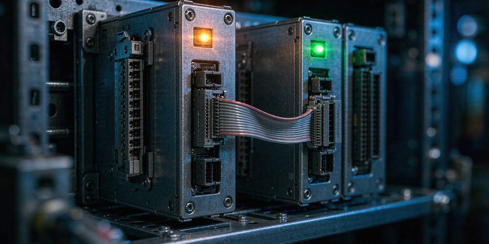
The STBY indicator signals the secondary module status within a redundant safety pair. According to ISA-84 safety standards, redundant hardware must verify memory synchronization before taking active control. A yellow flashing light usually indicates an intermediate state, such as boot-up or database qualification. Therefore, operators must not assume the secondary module is fully ready for automatic failover during this phase.

Evaluating Root Causes of Intermediate Yellow Flashing Statuses

Several factors cause the STBY LED to flash yellow on FC-RUSIO modules during operation. Modern factory automation environments demand strict hardware and firmware alignment between redundant pairs. An ongoing synchronization process or mismatched firmware version holds the module in a qualification loop. Moreover, minor communication faults across the redundant backplane prevent the standby unit from reaching fully synced status.

Ensuring Safety Integrity During Module Maintenance and Swaps

Safety System Integrity Level compliance requires strict verification before executing hot swaps. Field technicians must never rely solely on front panel LED indicators. Instead, operators should check the Experion PKS system diagnostics to confirm database consistency. In addition, technicians must review active bypasses and safety interlocks prior to cycling power on redundant I/O cards.

Step-by-Step Diagnostic Sequence for Honeywell I/O Troubleshooting

  1. Record All Module LEDs: Document the status of the FAULT, RUN, and STBY indicators simultaneously.
  2. Check System Diagnostics: Access the Safety Manager software to view detailed event logs and error codes.
  3. Verify Firmware Consistency: Confirm that the primary and secondary FC-RUSIO modules share identical firmware revisions.
  4. Inspect Backplane Connections: Ensure proper seating and clean physical connections along the rack backplane.

Best Practices for Maintenance and Safety System Readiness

Unplanned shutdowns often occur when technicians force failovers on unready standby modules. According to ARC Advisory Group reports, improper maintenance procedures cause nearly 20% of industrial unscheduled downtime. Therefore, maintenance teams must maintain verified software backups and update system documentation regularly. Always follow approved plant safety procedures before manipulating live SIS hardware.

B2B Procurement and Compatibility Insights for Honeywell Parts

Procurement teams must carefully verify exact part numbers when ordering replacement safety modules. For example, buying an FC-RUSIO-3224 module requires verifying backplane compatibility and terminal assembly revisions. Installing mismatched hardware revisions can delay synchronization and disrupt DCS communications. Powergear X Automation recommends consulting certified automation specialists to ensure seamless module integration.

Application Scenario: Refined Chemical Plant SIS Maintenance

A petrochemical processing facility experienced a persistent yellow flashing STBY light after replacing a secondary FC-RUSIO module. The engineering team initially suspected a defective replacement card. However, diagnostic software logs revealed that the primary module ran firmware version 2.1, while the new module contained version 2.4.

The technical team aligned the module firmware using Safety Manager software tools. Once the firmware versions matched, the STBY LED transitioned from flashing yellow to solid yellow within 45 seconds. This process successfully re-established full redundant synchronization without interrupting plant production.

To source original Honeywell safety modules and access expert support for your control systems, visit Powergear X Automation to find high-performance components for your facility.

Frequently Asked Questions (FAQ)

Q1: Does a yellow flashing STBY light mean the FC-RUSIO module is faulty?
No. A yellow flashing light typically indicates an intermediate transition state, such as memory synchronization or firmware validation, rather than an active hardware failure.

Q2: Can I manually trigger a failover while the STBY light is flashing yellow?
No. Forcing a failover while the secondary module is unverified can drop field signals and trigger an unintended safety trip across your DCS.

Q3: Where can I confirm the exact LED definitions for my FC-RUSIO module revision?
Always consult the official Honeywell Safety Manager Hardware Guide or check Experion PKS system diagnostics for your specific firmware revision.
Honeywell FC-PSU-UNI2450U Smoke Diagnosis & Power Supply Guide

Honeywell FC-PSU-UNI2450U Smoke at Power-On: Diagnostic Guide for Power Supply Faults

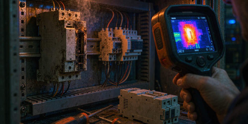
A sudden emit of smoke from a Honeywell FC-PSU-UNI2450U power supply during post-overhaul energization demands immediate technical investigation. Industrial control systems rely on stable 24VDC power rails to maintain continuous safety manager operations. However, field engineers cannot immediately attribute power-on smoke solely to bridge rectifier breakdown or capacitor aging. Powergear X Automation provides this engineering assessment to isolate internal component failures, inrush current surges, and external wiring faults in process automation environments.

Understanding the Safety Manager Power Architecture

The FC-PSU-UNI2450U serves critical safety system components in DCS and PLC hardware environments. This module delivers regulated 25–28 VDC output specifically designed for high-reliability process safety applications. Unlike general-purpose industrial automation power units, safety manager power supplies integrate precise voltage monitoring and fast-acting protection logic. Therefore, engineers must avoid substituting this unit with standard commercial power supplies during facility maintenance or cabinet overhauls.

Analyzing Input Rectifier Failures and Inrush Current Impacts

Primary AC rectification components face severe thermal and electrical stress during initial system energization. An internal short circuit inside the bridge rectifier causes a massive AC input current surge upon power-on. Consequently, this sudden current draw trips input protection fuses, damages printed circuit boards, and generates visible smoke. However, metal oxide varistors, primary MOSFET switching devices, and input suppression circuits produce identical symptoms. Engineers must perform diode junction testing and resistance checks before declaring the rectifier as the root cause.

Evaluating Electrolytic Capacitor Aging and Dielectric Breakdown

DC bus electrolytic capacitors experience electrolyte drying, elevated Equivalent Series Resistance, and internal insulation degradation over time. High ESR typically causes excessive ripple voltage and thermal buildup during steady-state operation. However, severely aged capacitors can suffer dielectric breakdown during power-on inrush events. Visual indicators include bulging safety vents, electrolyte residue, and localized PCB discoloration. Furthermore, secondary collateral damage from a failed switching transistor can mimic direct capacitor failure, requiring thorough circuit tracing.

Technical Specifications and Thermal Operating Limits

Honeywell hardware reference manuals define strict operational parameters for the FC-PSU-UNI2450U power module. The unit guarantees a full-load hold-up time of 100 milliseconds to bridge momentary utility voltage dips. Moreover, operating ambient temperatures above 50°C trigger thermal derating profiles that shorten capacitor lifespan. Industrial plants must maintain cabinet ventilation to prevent heat accumulation, as excessive ambient temperatures accelerate insulation breakdown in both power semiconductor junctions and filter capacitors.

Step-by-Step Commissioning Isolation Protocol

  1. Secure System Isolation: Lock out the AC supply immediately and never re-energize a smoking power supply repeatedly.
  2. Verify Line Input Parameters: Measure incoming AC voltage, supply frequency, and mechanical connector retention clips for proper installation.
  3. Isolate Downstream Loads: Disconnect output terminals to differentiate between internal PSU short circuits and external load faults.
  4. Perform Component Resistance Tests: Check primary switching MOSFETs, rectifier diodes, and input MOVs with an multimeter prior to re-applying power.

Field Guidelines for Installation and Physical Maintenance

Proper mechanical assembly prevents premature power supply failures during plant commissioning. The FC-PSU-UNI2450U utilizes locking DC connectors and AC input retention clips to withstand cabinet vibration. Engineers must maintain vertical mounting orientations to facilitate natural convection cooling across the internal heat sinks. In addition, cleaning cabinet dust filters and verifying cooling fan operation significantly reduces thermal stress on high-voltage primary components.

B2B Procurement and Version Compatibility Review

Replacing legacy safety manager power supplies requires careful verification of hardware revisions and system catalog numbers. Honeywell documentation specifies FC-PSU-UNI2450U version 2.1 as a direct upgrade for older V1.0 and V2.0 models. However, legacy cabinet backplanes may require additional mechanical adapter plates or wiring harness updates. Purchasing teams should verify exact part numbers, revision levels, and firmware support with certified automation suppliers before executing plant upgrades.

Application Scenario: Petrochemical Refinery Commissioning

During a planned turnaround at a chemical processing facility, maintenance crews re-energized a safety instrumented system cabinet containing an FC-PSU-UNI2450U module. The power supply emitted smoke instantly, tripping the main cabinet circuit breaker. The plant engineering team isolated the supply and performed benchtop component analysis.

The diagnostic revealed that an line voltage transient had shorted the primary MOV surge suppressor, which subsequently damaged the adjacent bridge rectifier. The DC bus capacitors remained fully functional. The team replaced the damaged power module with a verified unit, inspected the AC input line filtering, and successfully restored safety system communications without further downtime.

For high-performance industrial control hardware, genuine safety system components, and expert technical support, visit Powergear X Automation to explore our comprehensive automation product portfolio.

Frequently Asked Questions (FAQ)

Q1: Can an external short circuit on the 24VDC output cause the power supply to smoke?
No, the FC-PSU-UNI2450U features built-in electronic short-circuit protection on its output stage. An external DC load fault causes output voltage collapse or hiccup mode protection, rather than immediate primary-side smoking.

Q2: How do I distinguish between a failed bridge rectifier and a shorted MOSFET?
Unplug the power supply and use a digital multimeter in diode-check mode. A shorted bridge rectifier shows zero resistance across the AC input pins or DC bus rails, whereas a shorted MOSFET displays low resistance specifically between its drain and source terminals.

Q3: Is the FC-PSU-UNI2450U directly interchangeable with Honeywell C300 power supplies?
No. While both systems use 24VDC power architectures, the FC-PSU-UNI2450U belongs to the Safety Manager family and possesses specific mechanical form factors, pinouts, and safety certification levels distinct from C300 series hardware.

ABB CI867 Modbus TCP Zero-Data Fix & Byte Swap Guide

Troubleshooting ABB CI867 Modbus TCP Zero-Data Faults and Byte Swap Issues After Module Replacement

Replacing an industrial communication interface in a distributed control system (DCS) often presents unexpected challenges. Maintenance teams frequently observe that replacing an ABB CI867 Modbus TCP module results in all field data displaying zero. However, the physical Link LED on the Ethernet port shows normal operation. Powergear X Automation provides this troubleshooting guide to resolve data integrity issues in ABB System 800xA and AC 800M control systems.

Distinguishing Physical Ethernet Connectivity from Modbus Application Integrity

A solid Link LED indicates a healthy physical Layer 1 Ethernet connection. However, physical layer stability does not guarantee correct application layer data exchange. Modbus TCP operates as a client-server protocol requiring precise register mapping and matching data formats. According to industrial networking surveys, over 40% of post-replacement field errors stem from software configuration mismatches rather than hardware defects. Therefore, engineers must separate physical connectivity from data interpretation when diagnosing all-zero readings.

Understanding Byte Swap and Word Swap Dynamics in Process Automation

Modbus TCP transmits 16-bit register pairs using standard big-endian byte ordering. However, multi-register 32-bit values like floating-point numbers require careful byte and word alignment. Swapping high and low bytes alters integer values within a single 16-bit word. Conversely, word swapping exchanges the positions of two adjacent 16-bit registers. While a byte swap mismatch generates incorrect numerical values, it rarely causes every register to read zero simultaneously.

Identifying Root Causes of All-Zero Readings in Factory Automation

When every Modbus register displays zero after module replacement, investigate underlying configuration mismatches. Common causes include incorrect starting register addresses, offset errors, and unsupported Modbus function codes. For instance, requesting Function Code 03 instead of Function Code 04 can cause quiet read failures. In addition, uninitialized application variables or missing communication status flags force PLC and DCS logic to output zero values for safety.

Step-by-Step Commissioning Sequence for CI867 Module Integration

  1. Verify Physical Communication: Confirm active IP configuration, subnet masks, and ping connectivity between the CI867 and remote devices.
  2. Capture Raw Register Data: Use Control Builder software or a Modbus poll utility to inspect unformatted hexadecimal register values.
  3. Validate Register Addressing: Verify whether the field instrument utilizes zero-based or one-based Modbus register addressing.
  4. Check Byte Order Settings: Compare raw register hex codes against documented field device values before enabling software byte-swapping functions.
  5. Confirm Application Logic: Ensure communication status bits enable data transfer blocks within the AC 800M controller program.

Field Installation Standards and Compliance Practices

Robust field installation prevents intermittent data corruption in factory automation networks. Signal cables must maintain proper separation from high-voltage motor wiring to prevent electromagnetic interference. Furthermore, control cabinet installations must adhere to international grounding regulations under IEC 61000 standards. Engineering teams must document all firmware revisions and Control Builder settings prior to performing hardware maintenance.

B2B Procurement and Hardware Compatibility Insights

Procurement specialists must verify hardware revisions and firmware compatibility when purchasing replacement parts. Modern CI867A modules offer enhanced diagnostics but require specific System 800xA software versions. Simply matching a base part number does not guarantee seamless hot-swapping without configuration updates. Therefore, integration teams should validate firmware compatibility before installing spare parts during planned downtime.

Application Scenario: Refined Chemical Processing Line

A chemical plant replaced a faulty CI867 module connecting an AC 800M DCS to a rack of variable speed drives. Following the replacement, all motor speed and current feedback values dropped to zero, halting production interlocks. The Ethernet Link LED remained fully operational, leading technicians to suspect a corrupt drive program.

Engineers from Powergear X Automation inspected the system and discovered that the replacement module defaulted to Function Code 04 (Input Registers), whereas the drives required Function Code 03 (Holding Registers). Reconfiguring the Control Builder hardware tree restored raw communication instantly. A minor byte-swap adjustment on 32-bit float channels then returned accurate motor current readings within 30 minutes.

For certified spare parts and expert technical support on ABB AC 800M systems, visit Powergear X Automation to secure reliable hardware solutions for your plant infrastructure.

Frequently Asked Questions (FAQ)

Q1: Does a normal Link LED mean the CI867 module is transmitting Modbus data?
No. The Link LED only confirms physical layer connection to the network switch. It does not verify IP routing, Modbus TCP handshakes, or valid register polling.

Q2: How do I determine whether I need a Byte Swap or a Word Swap?
Examine raw hexadecimal data from a known non-zero register. If the individual bytes within a 16-bit register are reversed, apply a byte swap. If two adjacent registers in a 32-bit float are transposed, apply a word swap.

Q3: Can I drop a replacement CI867 module into an existing rack without software configuration?
While the CI867 supports module replacement, the hardware revision and firmware version must match the Control Builder project requirements. Always verify project settings and firmware compatibility before commissioning.

Replace ABB PP835A HMI with Third-Party OPC Touchscreens

Replacing Damaged ABB PP835A HMI with Third-Party Touchscreens via OPC Communication

Physical damage to an ABB PP835A touchscreen panel does not force plants to replace the entire DCS architecture. Operators can retain the AC 800M controller and its core control logic. By establishing an OPC communication layer, engineers can stream process variables to third-party HMIs seamlessly. Powergear X Automation presents this guide to explain how plants can maintain system stability using modern industrial automation solutions.

Understanding MMS Communication in AC 800M Control Systems

The AC 800M controller utilizes Manufacturing Message Specification (MMS) as its primary control network protocol. ABB documentation confirms that MMS handles project downloads, online diagnostics, and alarm communications. However, standard third-party HMIs cannot natively parse MMS data structures. Simply plugging an Ethernet cable into an AC 800M controller will not grant variable access. Therefore, system integrators must bridge the gap between MMS and standard Ethernet protocols.

The Role of ABB OPC Server in Protocol Translation

The ABB OPC Server for AC 800M collects field data from the controller via MMS. It then translates these values into standard OPC DA or OPC UA interfaces. As a result, third-party platforms like Siemens WinCC or Weintek HMIs can read process tags easily. This architecture protects the core control program, eliminating the need to rewrite complex controller logic. Consequently, plants save hundreds of engineering hours during panel retrofits.

Comparing OPC DA and OPC UA for Modern Plant Architectures

Legacy DCS installations heavily rely on OPC DA, which operates on Windows DCOM technology. While OPC DA offers fast local integration, it faces severe network security limitations. Conversely, OPC UA provides cross-platform compatibility, robust encryption, and built-in user authentication. Industrial automation trends show that over 70% of new factory automation upgrades now require OPC UA. Therefore, engineers should evaluate network security requirements before selecting their integration architecture.

Step-by-Step Commissioning Procedure for HMI Replacement

  1. Audit Existing Tag Sourcing: Map all process variables, data types, and alarm states from the original PP835A project.
  2. Configure Tag Access Rights: Establish read-only permissions during initial testing to protect running production equipment.
  3. Deploy Independent Test Environment: Validate OPC Server connections and tag browsing offline before connecting to the live control network.
  4. Execute Staged Variable Testing: Verify digital status indicators, analog values, and alarm quality flags prior to enabling write commands.

Field Installation Practices and Control Network Optimization

Connecting new HMIs directly to a live control network introduces unnecessary operational risks. Continuous polling of thousands of tags can overload the AC 800M Ethernet communication modules. Engineers must optimize tag update rates based on process dynamics. For instance, temperature and tank level tags require slower scan times than fast motion loops. Moreover, field technicians must follow strict isolation practices during commissioning to prevent accidental trips.

Integrating Third-Party HMIs via OPC Gateway Architecture

Deploying a dedicated OPC Gateway creates a secure buffer between the AC 800M control network and external HMIs. The gateway retrieves data via MMS and exposes encrypted OPC UA endpoints to third-party devices. Furthermore, this architecture simplifies future plant expansions, such as integrating SCADA, Historian, or MES software. As a result, plant managers achieve a modular and scalable industrial automation infrastructure.

Application Scenario: Petrochemical Facility HMI Migration

A continuous chemical processing plant suffered a screen failure on an aging ABB PP835A panel connected to an AC 800M controller. Sourcing an exact Panel 800 replacement required a four-week lead time, threatening costly plant downtime. The engineering team deployed a third-party touchscreen HMI using the existing ABB OPC Server.

First, the team created a comprehensive Tag Mapping List to mirror the original PP835A variable addresses. Second, they configured an OPC UA client interface on the new HMI to establish secure data exchange. Finally, they conducted staged read-write validation on a isolated network segment. The new HMI went live within 48 hours without modifying a single line of AC 800M controller code.

For high-performance control system components and expert technical support on DCS migrations, visit Powergear X Automation to explore reliable hardware solutions for your plant.

Frequently Asked Questions (FAQ)

Q1: Can I connect a Siemens or Weintek HMI directly to an AC 800M without an OPC Server?
Direct Ethernet connections generally fail because standard HMIs lack native AC 800M MMS protocol drivers. You must use an ABB OPC Server, a dedicated OPC Gateway, or an HMI model with a specialized AC 800M driver.

Q2: Do I need to reprogram the AC 800M controller when replacing the PP835A?
No. The core control program remains untouched. You only need to map the new HMI tags to the process variables already published by the controller or OPC Server.

Q3: What causes write failure when controlling pumps or valves from a new HMI?
Write failures usually result from incorrect DCOM security settings in OPC DA, misconfigured user permissions in OPC UA, or tag data type mismatches between the HMI and the OPC Server.

Fix GE Fanuc IC695CPE305 CPU Random Reboots | RX3i Guide

Why GE Fanuc IC695CPE305 CPUs Experience Random Reboots and How to Fix Them

In modern industrial automation, unexpected controller reboots cause severe operational downtime. The GE Fanuc PACSystems RX3i IC695CPE305 CPU serves as a core processing unit in complex factory automation systems. However, field engineers often report random CPU reboots after approximately two years of continuous operation. Powergear X Automation provides this practical engineering guide to diagnose root causes, eliminate recurring downtime, and optimize PLC stability.

Analyzing Power Supply Degradation and Transient Dips in DCS Architecture

Power quality issues represent the primary trigger for spontaneous PLC reboots. Although power supply units work reliably at installation, internal capacitors degrade gradually over time. Consequently, high-current switching events from nearby heavy motors create momentary voltage sags. These micro-second voltage dips bypass standard multimeters but trigger the CPU under-voltage protection circuit. Therefore, maintenance teams must capture real-time power waveforms using a high-speed oscilloscope before replacing hardware.

Evaluating Thermal Stress and Long-Term Cabinet Enclosure Conditions

Heat accumulation degrades delicate microelectronics inside programmable logic controllers. Enclosure filters clog with industrial dust after extended operation without regular maintenance. As a result, internal cabinet temperatures steadily climb beyond the recommended 60°C operating limit. Excess heat triggers thermal protection mechanisms inside the CPU processor. Moreover, long-term thermal expansion loosens backplane connectors, creating intermittent physical connection drops during peak operational shifts.

Investigating CPU Firmware Restrictions and Software Watchdog Events

Software anomalies frequently mimic hardware failures in modern control systems. According to industrial control industry surveys, over 30% of unexpected PLC restarts originate from software watchdog timeouts. Heavy non-volatile memory write operations or unhandled system interrupts lock up the execution thread. Consequently, the internal watchdog timer resets the CPU to prevent erratic machine behavior. Engineers must analyze the PAC Machine Edition fault table before clearing CPU error logs.

Step-by-Step Diagnostic Sequence for Resolving CPE305 Reboots

  1. Preserve Diagnostic Error Tables: Connect to the CPU via PAC Machine Edition immediately and export the complete controller fault log.
  2. Monitor DC Power Quality: Install a transient power recorder to log 24V DC bus stability during heavy motor startup sequences.
  3. Inspect Physical Connections: Check backplane connectors, terminal blocks, and Energy Pack module cables for corrosion or mechanical looseness.
  4. Verify Cabinet Thermal Profile: Measure internal panel temperatures using thermal imaging cameras under full operational loads.

Inspecting Energy Pack Performance and Power Loss Backup Systems

The IC695CPE305 processor utilizes an Energy Pack capacitor module to preserve volatile RAM data during power outages. However, aging Energy Pack units can develop internal short circuits or fail to maintain adequate charge holding capacity. When an unstable Energy Pack draws excessive current from the CPU internal rail, it induces voltage drops across the processor board. Therefore, field technicians should regularly test and replace aging backup energy modules according to manufacturer maintenance schedules.

B2B Procurement Strategies and Backward Compatibility Verification

Replacing an IC695CPE305 module requires careful compatibility evaluation rather than quick component swapping. System integrators must verify CPU hardware revisions, installed firmware builds, and backplane bus speeds. While modern Emerson RX3i controllers support legacy Series 90-30 I/O modules, firmware mismatches can cause backplane communication errors. Procurement managers must review technical specifications thoroughly before scheduling system upgrades during maintenance windows.

Application Scenario: Chemical Plant Processing Line Recovery

A continuous chemical processing plant experienced random IC695CPE305 reboots every few days, interrupting critical batch mixing operations. The maintenance team initially suspected a defective CPU board and replaced the hardware, yet the reboots persisted. Powergear X Automation specialists audited the panel installation and discovered that aging panel cooling fans had failed, causing internal enclosure temperatures to reach 68°C.

The engineering team installed new cabinet ventilation fans and cleaned the clogged dust filters. Additionally, they updated the CPU firmware to the latest revision and adjusted the power supply monitoring parameters. These targeted actions reduced panel temperatures to a stable 38°C, completely eliminating random CPU reboots and restoring 100% processing line uptime.

To source reliable GE Fanuc PACSystems RX3i components and receive expert technical troubleshooting support, visit Powergear X Automation today for your factory automation needs.

Frequently Asked Questions (FAQ)

Q1: Should I immediately replace my IC695CPE305 CPU when random reboots start?
No. You should first investigate external power supply dips, cabinet overheating, and backplane looseness. Replacing the CPU will not resolve external electrical or thermal issues.

Q2: How does the Energy Pack affect CPU boot behavior on the PACSystems RX3i?
The Energy Pack powers the CPU memory save process during shutdown. A degraded or shorted Energy Pack can cause startup faults or force the CPU into reboot loops.

Q3: What tools are required to capture voltage transients causing PLC reboots?
Standard multimeters are too slow to detect millisecond voltage sags. You need a digital storage oscilloscope or a specialized power quality analyzer to capture brief DC power dips.

Troubleshoot Honeywell XNX Gas Detector Blank Display Errors

Troubleshooting Honeywell XNX Gas Detector Blank Display: Display Module or Main Board Failure?

A Honeywell XNX Universal Gas Detector may keep its green power LED lit while the LCD screen turns completely blank. However, this condition does not automatically indicate a defective main board. Faults often originate from the display assembly, internal power supply, or ribbon cable connection. Powergear X Automation presents this technical troubleshooting guide to isolate gas detection faults efficiently without replacing expensive electronic assemblies unnecessarily.

The Operational Importance of Local Gas Detector Displays

Industrial facilities rely on Honeywell XNX gas detectors to provide immediate toxic or flammable gas measurements. Local LCD displays allow operators to view gas concentrations, diagnostic faults, and calibration status directly in hazardous areas. When the screen turns blank, operators lose real-time local visibility. According to industrial safety field reports, quick fault isolation reduces system downtime significantly. Therefore, field technicians must isolate display failures from core processing issues before ordering replacement components.

Power LED Status Does Not Prove Display Circuit Health

An illuminated green power LED simply confirms that the primary 24V DC supply reaches the transmitter terminals. However, it does not guarantee that the internal 3.3V DC LCD rail operates correctly. The main board converts input power through separate step-down regulators to drive the display processor and backlight. Consequently, a faulty internal power converter can freeze the screen while the power LED stays lit. Technicians must check secondary voltage rails before assuming total main board failure.

Evaluating Communication Interfaces to Verify Main Controller Health

Technicians should check whether the main processor continues to communicate with central control systems. If the transmitter sends valid 4-20mA signals or responds to HART handheld communicators, the main board remains functional. Therefore, active fieldbus or DCS communications confirm that the central processor is executing its code. In this scenario, the failure isolates directly to the display POD assembly, ribbon cable connector, or local LCD driver circuit.

Key Compatibility Factors Before Ordering XNX Replacement Components

Honeywell XNX gas detectors feature modular hardware architectures with various personality and option boards. Purchasing a replacement display module based solely on the enclosure appearance often leads to compatibility issues. Technicians must verify the complete model configuration code, PCB revision, and firmware version before purchasing hardware. Furthermore, hardware substitutions in hazardous locations must strictly adhere to ATEX or IECEx certified maintenance guidelines.

Step-by-Step Diagnostic Sequence for Fault Isolation

  1. Check Communication Status: Connect a HART communicator or monitor the DCS 4-20mA input channel to verify processor activity.
  2. Isolate Power and Inspect Cabling: De-energize the unit, open the flameproof enclosure, and inspect the internal ribbon cables for corrosion.
  3. Verify Internal Voltage Rails: Apply power safely and measure the secondary internal 3.3V DC test points using an approved multimeter.
  4. Perform Controlled Component Substitution: Install a known-good compatible display POD assembly to observe whether normal screen function resumes.

Environmental Hazards Impacting Gas Detection Electronics

Industrial plants expose field electronics to extreme environmental stresses over extended operational cycles. Heavy vibration from nearby pumps or compressors can loosen internal ribbon cable connectors over time. Moreover, thermal cycling and high humidity encourage moisture condensation inside the housing, causing micro-corrosion on delicate display pin headers. Installing high-quality seals and applying recommended terminal torque specifications prevents environmental damage effectively.

Procurement Guidance and B2B Cost Optimization

Ordering a full main transmitter assembly for a simple LCD display failure increases maintenance costs substantially. Procurement managers should establish spare parts inventories based on component-level failure rates. Sourcing individual display modules or personality boards reduces emergency repair budgets dramatically. However, buyers must ensure that suppliers verify exact hardware revision compatibility before dispatching replacement components.

Application Scenario: Offshore Platform Gas Detector Maintenance

An offshore oil platform reported a blank LCD screen on an XNX transmitter monitoring hydrogen sulfide near a compressor skid. The power LED remained green, but operators could not perform local zero calibrations. Replacing the entire transmitter housing would require a lengthy hot-work permit and system shutdown.

The instrument team connected a HART communicator and confirmed that the transmitter was actively sending a normal 4.0mA signal to the DCS. By executing a controlled display POD substitution during scheduled maintenance, the team restored the display in fifteen minutes. This targeted repair saved thousands of dollars in downtime and preserved the original explosion-proof enclosure seals.

For high-reliability gas detection components, spare parts, and expert automation support, visit Powergear X Automation to explore our extensive inventory of field instrumentation solutions.

Frequently Asked Questions (FAQ)

Q1: Does a blank XNX LCD screen mean the 4-20mA alarm output has failed?
Not necessarily. If the main processor remains active, the transmitter will continue outputting valid 4-20mA gas readings and trigger remote alarms normally despite the blank local display.

Q2: Can I swap an XNX display module without turning off the power?
No. You must de-energize the transmitter before opening the explosion-proof housing or disconnecting internal electronics to prevent electrical arcing in hazardous environments.

Q3: What causes an XNX display to freeze or show scrambled characters?
Scrambled characters usually result from electromagnetic interference (EMI), loose ribbon cable connections, or momentary voltage dips on the internal 3.3V DC power rail.

IC695CPE330 Network Storm Analysis | Dual-Core PLC Stability

How IC695CPE330 Handles Network Storms: Dual-Core Architecture and PLC Resilience Guide

In modern industrial automation, Ethernet connectivity plays a critical role in high-speed data exchange. Engineers frequently debate whether a severe broadcast storm will crash an Emerson PACSystems RX3i controller. However, claiming that network overload always leads to a CPU system crash is technically inaccurate. The IC695CPE330 CPU features an advanced dual-core processor design that separates core control logic from network communication tasks. Powergear X Automation presents this technical analysis to examine how the IC695CPE330 manages extreme network traffic and maintains system stability.

Understanding the Dual-Core Processing Architecture in Advanced Control Systems

The IC695CPE330 controller utilizes two distinct processing cores to maximize operational stability. One dedicated core processes ladder logic execution and I/O scanning functions. Meanwhile, the second core manages Ethernet protocol handling and external communications. Furthermore, independent Network Interface Controllers (NICs) manage LAN1 and LAN2 separately. This physical isolation prevents high TCP or broadcast traffic from freezing the main control loop. Therefore, a heavy network storm typically causes temporary communication drops rather than a complete PLC logic failure.

Evaluating Ethernet Traffic Thresholds in Factory Automation Networks

Gigabit Ethernet capacity provides high data throughput for modern DCS and PLC architectures. However, operating at 1 Gbps does not make the controller immune to excessive multicast or broadcast packets. Heavy protocol traffic, such as SRTP or Ethernet Global Data (EGD), requires continuous packet processing. As a result, extreme network storms can overload the internal network stack. While the PLC remains in RUN mode, HMI screens may freeze and SCADA monitoring might disconnect temporarily.

Implementing Network Segmentation Using Dual Independent LAN Ports

The IC695CPE330 provides two independent Ethernet LAN interfaces that must operate on different IP subnets. Engineers should never bridge LAN1 and LAN2 into the same broadcast domain. Connecting LAN1 to the enterprise IT layer and LAN2 to the local control network creates a logical security barrier. Consequently, broadcast traffic generated on office computers cannot enter the local PLC I/O network. Proper subnetting remains the most effective defense against network-induced downtime.

Field Guidelines for Preventing Network Loops and Packet Duplication

Unintended Layer-2 loops cause severe packet duplication and rapid network degradation. According to industrial networking standards, Ethernet switches should follow structured tree topologies unless configuring managed ring redundancy. When network storms occur, field engineers must follow a systematic diagnostic sequence:

  • Check Physical Topologies: Inspect the switch cabling to verify that redundant links have Spanning Tree Protocol (STP) enabled.
  • Identify MAC Flapping: Monitor managed switch logs for rapid MAC address swapping across switch ports.
  • Inspect Broadcast Statistics: Use switch diagnostics to measure current broadcast and multicast packet rates.
  • Verify Subnet Configurations: Ensure LAN1 and LAN2 IP addresses do not overlap with adjacent subnets.

Diagnostic Methods for Differentiating Network Dropping from CPU Crashes

Troubleshooting requires distinguishing between a communication timeout and a true CPU hardware fault. If the PLC continues executing its logic loop while HMI communications fail, the CPU core is functioning normally. Engineers should execute the following steps during network anomalies:

  1. Preserve System Logs: Collect the CPU fault table and Ethernet exception logs before rebooting the controller.
  2. Isolate Network Segments: Temporarily disconnect the enterprise uplink cable from the LAN1 port.
  3. Monitor Scan Times: Check whether the controller logic scan time remains stable during high network traffic.
  4. Verify LED Diagnostics: Confirm that the CPU RUN LED stays solid green while analyzing port activity lights.

B2B Sourcing and Hardware Compatibility Insights

System integrators must evaluate total network architecture when upgrading RX3i control systems. Procuring advanced CPUs like the IC695CPE330 ensures high processing capacity for complex machinery. However, long-term reliability depends heavily on using industrial managed switches equipped with Storm Control and IGMP Snooping features. Procurement managers should source genuine hardware components to ensure full firmware compatibility across all Ethernet modules.

Application Scenario: Automotive Assembly Line Communication Isolation

An automotive manufacturing plant experienced frequent SCADA disconnections when an office video stream saturated the main network. The plant utilized an IC695CPE330 CPU connected to a flat enterprise network. Heavy broadcast traffic overwhelmed the Ethernet stack, causing SRTP communication timeouts across the assembly line.

Engineers resolved the issue by implementing strict network segmentation. They reconfigured the IC695CPE330 to route enterprise SCADA traffic through LAN1 on a dedicated VLAN. Meanwhile, local I/O drops and HMI panels were isolated on LAN2 using a managed industrial switch with active Storm Control. This dual-subnet strategy eliminated communication losses completely without requiring CPU hardware replacements.

To upgrade your industrial network infrastructure with high-performance controllers and automation components, visit Powergear X Automation for expert technical support and genuine module sourcing.

Frequently Asked Questions (FAQ)

Q1: Will a network storm cause the IC695CPE330 CPU to go into STOP mode?
No, a standard network storm rarely causes the CPU to stop. The dual-core architecture isolates logic execution from communication tasks, keeping the PLC in RUN mode during network overloads.

Q2: Can I assign the same IP subnet to both LAN1 and LAN2 ports?
No, LAN1 and LAN2 must use distinct IP subnets. Overlapping IP ranges can cause routing errors, intermittent communications, or complete network interface failure.

Q3: What switch features best protect the IC695CPE330 from broadcast storms?
Managed industrial switches with Storm Control, VLAN segmentation, and IGMP Snooping provide the best protection against broadcast and multicast network storms.

Honeywell CC-PUIO31 HART Support & Pass-Through Fix Guide

Why the Honeywell CC-PUIO31 Supports HART 7 but Blocks Handheld Communicator Pass-Through Data

In modern industrial automation, the Honeywell Experion PKS Series C CC-PUIO31 serves as a highly flexible 32-channel Universal Input/Output (UIO) module. Process control engineers widely deploy this module across distributed control systems (DCS) for chemical, pharmaceutical, and refining facilities. Official Honeywell technical specifications confirm that the CC-PUIO31 supports HART 7 protocol on analog channels through dedicated per-channel modems. However, field technicians often report that HART handheld communicators, such as the Emerson 475 or AMS Trex, fail to establish online pass-through communication when connected directly to the field terminals. Powergear X Automation presents this diagnostic guide to clarify the architectural differences between system-level HART integration and direct physical pass-through.

Understanding the Dual Functionality of Universal Input Output Architecture

The CC-PUIO31 module allows software configuration for each of its 32 channels as Analog Input (AI), Analog Output (AO), Digital Input (DI), or Digital Output (DO). However, HART communication functionality operates exclusively when channels are configured for analog signals. According to industry field surveys, over 30% of HART communication issues stem from channel misconfigurations during system commissioning. Therefore, engineers must verify that the channel software profile matches the physical 4-20mA loop type before attempting HART diagnostics.

System-Level HART Integration versus Direct Field Pass-Through Mechanics

A fundamental distinction exists between system-level HART data integration and physical signal pass-through. The CC-PUIO31 module routes HART digital commands through the C300 controller to Honeywell Field Device Manager (FDM) software. Conversely, connecting an external handheld communicator directly to the module terminal block introduces a secondary HART master onto the current loop. Because the internal HART modem actively polls the field transmitter, token-passing conflicts or signal attenuation across the Input Output Termination Assembly (IOTA) can prevent external communicators from establishing a stable connection.

The Critical Role of Loop Impedance and Signal Conditioners

HART digital communication relies on Frequency Shift Keying (FSK) superimposed on the analog 4-20mA current signal. Reliable signal transmission requires a minimum loop impedance of 230 ohms, as mandated by the HART Communication Foundation standards. In factory automation environments, signal isolators, intrinsic safety barriers, or surge protectors frequently attenuate high-frequency HART signals. While the DCS continues to display accurate process variable (PV) readings, these inline devices block the FSK signal, preventing handheld communicators from detecting the field instrument.

Step-by-Step Commissioning Procedure for HART Communication Issues

  1. Measure Loop Current: Verify that the analog circuit maintains a valid 4-20mA current range using a calibrated multimeter.
  2. Confirm DCS Process Variable: Ensure the CC-PUIO31 module correctly registers the analog PV on the Experion PKS station.
  3. Verify Channel Assignment: Check the Experion database to confirm the channel is configured as AI or AO with HART enabled.
  4. Check System Master Activity: Temporarily pause FDM or asset management polling to avoid HART master collision during handheld connection.
  5. Inspect Inline Barrier Compatibility: Confirm that all isolators and barriers on the IOTA assembly explicitly support HART pass-through.

Physical Installation Practices and Field Wiring Reliability

Physical wiring integrity directly impacts HART communication stability in high-vibration manufacturing environments. Loose terminal screws, poor shield grounding, or improper 24V DC power distribution introduce electrical noise that corrupts digital frames. Maintenance teams should inspect IOTA models, such as the non-redundant CC-TUIO31 or redundant CC-TUIO41, to ensure proper ground termination. Proper installation prevents intermittent communication drops without requiring module replacements.

B2B Procurement Considerations: Universal I/O versus Dedicated HART Modules

Procurement managers often debate whether to specify the universal CC-PUIO31 module or dedicated HART AI modules like the CC-PAIH01. While the CC-PUIO31 offers channel-type flexibility and reduces spare parts inventory, dedicated HART modules provide higher channel density for pure analog installations. Additionally, system upgrades from legacy CC-PUIO01 modules require careful verification of Experion PKS software releases and IOM firmware compatibility to preserve existing HART asset management functions.

Application Scenario: Refining Unit Asset Management Optimization

A petrochemical refinery deployed Honeywell CC-PUIO31 modules across a newly expanded hydrocracker unit. During pre-commissioning, instrument technicians could not read diagnostic data using AMS Trex communicators at the junction boxes, although the DCS displayed stable pressure readings. The engineering team initially suspected defective I/O modules.

Powergear X Automation analyzed the field loop architecture and identified non-HART-compliant signal isolators installed between the field transmitters and the CC-TUIO41 IOTA terminals. Replacing these isolators with HART-transparent units and adjusting the FDM polling cycle resolved the issue. The modification restored full HART pass-through capability, allowing seamless handheld communication and FDM asset tracking without compromising 4-20mA control loops.

To source original Honeywell Series C hardware and explore advanced DCS solutions, visit Powergear X Automation for technical expertise and reliable component delivery.

Frequently Asked Questions (FAQ)

Q1: Can I use a HART handheld communicator on a CC-PUIO31 channel configured as DI or DO?
No. The CC-PUIO31 module enables HART communication exclusively on channels configured for analog input or output operations.

Q2: Why does my handheld communicator fail to connect even though FDM reads the instrument fine?
FDM communicates through the internal HART modem across the Experion network. Handheld communicators connect physically to the local loop, where inline barriers or impedance issues may block the local FSK signal.

Q3: Are CC-PUIO01 and CC-PUIO31 modules directly interchangeable in Experion PKS?
Not automatically. While both belong to the Universal I/O family, hardware replacement requires checking Experion release levels, firmware revisions, and database channel assignments prior to installation.

Fix TM200CE24T Unlit Ethernet LED & Machine Expert Basic Faults

Troubleshooting Schneider TM200CE24T Unlit Ethernet LEDs and Machine Expert Basic Discovery Failures

In modern factory automation, reliable Ethernet connectivity ensures efficient programming, commissioning, and system diagnostics. The Schneider Electric Modicon TM200CE24T programmable logic controller serves compact machinery across various industrial sectors. However, field engineers frequently encounter situations where the Ethernet LED remains unlit and software discovery fails. Powergear X Automation presents this step-by-step diagnostic guide to help technicians resolve physical link failures and software communication errors in control systems.

Diagnosing Physical Layer Faults and Ethernet LED Status Indicators

Physical layer integrity forms the baseline for all Ethernet-based industrial automation network communications. An unlit Link/Activity LED usually indicates an unpowered PLC, broken RJ45 cabling, or damaged port hardware. According to industrial maintenance statistics, physical cabling issues account for nearly 70% of network field faults. Continuous machine vibration often damages mechanical RJ45 latch clips and degrades solder joints inside control cabinets. Therefore, engineers must test the connection using a known good, industrial-grade CAT5e cable directly between the PC and controller.

Resolving IP Subnet Mismatches and Network Adapter Conflicts

EcoStruxure Machine Expert – Basic cannot discover PLCs located on different IP subnets without valid routing. For instance, a PC on subnet 192.168.0.x fails to auto-detect a controller configured on 192.168.1.x. Moreover, active Wi-Fi connections, VPN tunnels, and virtual network adapters often intercept local broadcast packets. As a result, engineers should temporarily disable secondary adapters and assign a static IP address to the primary Ethernet interface before refreshing device lists.

Evaluating Software Platform Compatibility and Firmware Alignment

Software version mismatches frequently prevent successful PLC discovery and project downloads. The Modicon M200 family requires the dedicated EcoStruxure Machine Expert – Basic programming environment. Attempting to connect via standard Machine Expert or legacy SoMachine platforms results in empty discovery lists. In addition, outdated software versions lack support for newer controller firmware revisions. Therefore, control engineers must verify software compatibility before attempting firmware upgrades or project transfers.

Step-by-Step Commissioning Procedure for Ethernet Connection Recovery

  1. Verify Power Supply Inputs: Measure 24VDC terminal voltages to confirm stable power distribution to the CPU module.
  2. Test Direct Ethernet Cabling: Bypass unmanaged switches and connect the PC directly to the PLC using a tested industrial patch cable.
  3. Isolate Computer Network Adapters: Disable Wi-Fi, VPNs, and virtual network interfaces inside Windows Network Connections.
  4. Assign Static Local IP Address: Configure the computer Ethernet adapter to match the default network segment of the controller.
  5. Execute Device Refresh in Software: Open Machine Expert – Basic, navigate to Commissioning, and perform an Ethernet Device Refresh.

B2B Procurement and PLC Module Replacement Strategy

Procurement managers should evaluate systemic installation factors before classifying a unresponsive controller as hardware failure. Replacing a TM200CE24T PLC requires verifying I/O point counts, transistor output types, and application software compatibility. Furthermore, upgrading legacy machine controllers demands careful review of expansion bus limits and fieldbus communication protocols. Investing in surge-protected 24VDC power supplies and shielded Ethernet connectors extends hardware operational lifespans significantly.

Application Scenario: Packaging Machine Communication Recovery

A high-speed food packaging line experienced sudden communication loss with an integrated TM200CE24T PLC during routine operation. The Ethernet LED on the CPU module turned completely dark, preventing Machine Expert – Basic from locating the device. The maintenance team initially suspected internal hardware failure and considered replacing the PLC.

Following the Powergear X Automation diagnostic protocol, engineers discovered that severe cabinet vibration had fractured the RJ45 port pins on the unmanaged switch. Replacing the damaged patch cable and securing the conduit reduced physical stress on the port. Consequently, the Ethernet LED illuminated immediately, and the programming software successfully restored full online diagnostics without requiring PLC replacement.

To source reliable automation hardware and explore high-performance PLC components, visit Powergear X Automation for expert technical solutions and system support.

Frequently Asked Questions (FAQ)

Q1: Does an unlit Ethernet LED always mean the TM200CE24T PLC is damaged?
No. An unlit LED usually indicates a lack of physical carrier signal, which commonly stems from loose cabling, unpowered switches, or disabled PC network interfaces rather than internal PLC failure.

Q2: Can I use standard EcoStruxure Machine Expert to program the TM200CE24T?
No. The Modicon M200 series specifically requires EcoStruxure Machine Expert – Basic. The standard edition software will not recognize the controller during network scans.

Q3: How do I find the IP address of a TM200CE24T if software auto-discovery fails?
You can use a third-party Wireshark packet analyzer to capture ARP broadcast packets during PLC power-up, or reset the controller to its default factory IP configuration using the hardware dip switches.

Troubleshooting 140DAM59000 Output Failures in Quantum PLCs

Emergency Repair and Troubleshooting Guide for Schneider Modicon Quantum 140DAM59000 Output Failure

In mature legacy distributed control systems (DCS) and programmable logic controllers (PLC), output channels occasionally fail to turn off. Field technicians frequently diagnose this behavior as a welded contact error on the output module. However, the Schneider Electric Modicon Quantum 140DAM59000 is a discrete combination module featuring 16 inputs and 8 outputs at 115 Vac rated at 0.5 A per point. Powergear X Automation presents this troubleshooting guide to isolate output channel faults and execute safe emergency workarounds without causing unneeded downtime.

Understanding the Core Value of Modicon Quantum Discrete I/O Architecture

Industrial automation infrastructure in chemical plants and utilities relies heavily on stable 115 Vac control loops. When an actuator remains energized after the PLC commands an off state, maintenance crews must act quickly. Engineers must determine whether the fault stems from an external shorted contactor coil or an internal 140DAM59000 output failure. Implementing structured diagnostics prevents misdiagnosing healthy hardware and ensures continuous operation for critical process control systems.

Technical Insights: Load Limits and Grouped Output Protection

The 140DAM59000 module provides eight 115 Vac discrete outputs arranged into two distinct groups of four channels. Each output point handles up to 0.5 A of continuous load current. However, driving inductive loads like large contactor coils or solenoid valves generates high inductive voltage spikes. Without proper inductive surge suppression, these transients stress internal solid-state switching components. Consequently, an unsuppressed inductive load can short-circuit the output channel or weld external interposing contactor contacts.

Differentiating 115 Vac AC Modules from 24 Vdc Transistor Modules

A common error in factory automation maintenance involves applying 24 Vdc troubleshooting practices to 115 Vac AC circuits. For instance, the Schneider 140DDM39000 module handles 24 Vdc signals, whereas the 140DAM59000 operates exclusively on 115 Vac power. Mixing these voltage levels or wiring intermediate 24 Vdc relays into a 115 Vac output loop damages internal circuitry. Maintenance engineers must always verify the module part number and physical wiring before attempting any emergency modifications.

Step-by-Step Diagnostic Method for Suspected Output Channel Failure

  1. Command Channel OFF in PLC: Set the logic bit to OFF within the Quantum programming software.
  2. Measure Voltage at Output Terminal: Check for persistent 115 Vac output voltage at the module terminal block.
  3. Disconnect the Field Load Cable: Isolate the field wiring safely to separate the I/O module from external machinery.
  4. Re-test Terminal State: If voltage remains present after disconnecting the load, the module output channel has failed closed.

Emergency Restoration Using Spare Outputs and Interposing Relays

When a single output point on the 140DAM59000 fails closed and no spare module exists, engineers can use an unused healthy channel. Re-route the PLC logic address to an available spare output point on the module. Always install an interposing relay between the 140DAM59000 output terminal and the heavy inductive load. This interposing relay isolates the PLC output from high inrush currents and protects the module from future electrical breakdown.

Safety Boundary Protocol: Emergency Bypass Restrictions

Temporary wiring modifications can restore standard auxiliary equipment during emergency production runs. However, safety standards strictly prohibit bypassing automated safety instrumented systems (SIS) or emergency shutdown (ESD) interlocks. Never force PLC output bits or jumper physical terminals on high-pressure cutoffs, flame detectors, or emergency stop circuits. Critical safety loops require official replacement parts and full validation to maintain industrial safety compliance.

Preventing Repeated Output Channel Damage After Module Replacement

Replacing a damaged 140DAM59000 module without addressing field load issues often leads to immediate repeat failures. Inductive back-EMF from unsuppressed AC solenoids rapidly destroys fresh switching components. Field technicians should verify coil voltage, measure steady-state current, and install RC snubber networks across all AC inductive loads. Proper surge suppression extends hardware life and protects factory automation systems from unexpected downtime.

B2B Procurement and Hardware Compatibility Guidelines

Procurement teams sourcing replacement legacy Quantum modules must evaluate several technical parameters. You cannot replace a 140DAM59000 module using an arbitrary 8-point output card. Purchasing agents must cross-reference input/output point counts, group isolation voltage, continuous current ratings, and backplane firmware compatibility. Reviewing exact module nameplates and hardware manuals ensures smooth drop-in replacements during scheduled maintenance windows.

Application Scenario: Chemical Dosing Pump Output Emergency Recovery

A water treatment facility experienced a critical fault when a 115 Vac chemical dosing pump failed to stop. The operator issued a stop command from the DCS, but the pump continued running. Troubleshooting revealed that the assigned 140DAM59000 output point had shorted internally due to repetitive solenoid voltage spikes. Because spare modules were out of stock, the team implemented a quick workaround.

The engineer rewired the signal cable to an unused healthy output channel on the same 140DAM59000 module. They updated the logic mapping in the PLC software and added an external 115 Vac interposing relay with an RC snubber across the pump solenoid coil. This modification successfully restored automated pump control within two hours, keeping the plant operational while procurement sourced a permanent replacement module.

To source authentic Schneider Electric Modicon Quantum components and explore reliable industrial automation solutions, visit Powergear X Automation for technical expertise and inventory support.

Frequently Asked Questions (FAQ)

Q1: Is the Schneider 140DAM59000 a relay output module or a solid-state AC output module?
The 140DAM59000 is a discrete combination module featuring 16 AC inputs and 8 AC outputs rated at 115 Vac, 0.5 A per point with grouped fusing. Always check the official hardware manual and module nameplate for precise switching element specifications.

Q2: Can I fix a shorted 140DAM59000 output channel by resetting or clearing PLC memory?
No. A shorted or failed-closed output channel represents physical hardware degradation within the output stage. Clearing PLC memory or forcing logic states cannot repair damaged electronic components.

Q3: What snubber protection should I install for 115 Vac inductive loads on this module?
Install an appropriately rated RC (Resistor-Capacitor) snubber network directly across the AC contactor coil or solenoid terminals. This absorbs inductive energy spikes and protects the 140DAM59000 output channel during de-energization.

Back to Top
Product has been added to your cart