
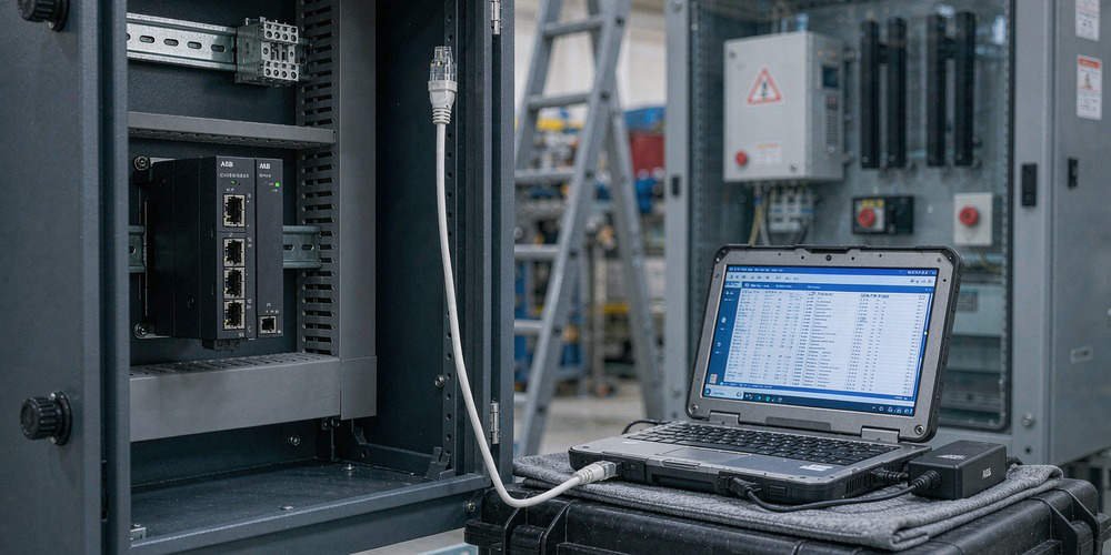
Troubleshooting ABB CI867 Modbus TCP Zero-Data Faults and Byte Swap Issues After Module Replacement
Replacing an industrial communication interface in a distributed control system (DCS) often presents unexpected challenges. Maintenance teams frequently observe that replacing an ABB CI867 Modbus TCP module results in all field data displaying zero. However, the physical Link LED on the Ethernet port shows normal operation. Powergear X Automation provides this troubleshooting guide to resolve data integrity issues in ABB System 800xA and AC 800M control systems.

Distinguishing Physical Ethernet Connectivity from Modbus Application Integrity
A solid Link LED indicates a healthy physical Layer 1 Ethernet connection. However, physical layer stability does not guarantee correct application layer data exchange. Modbus TCP operates as a client-server protocol requiring precise register mapping and matching data formats. According to industrial networking surveys, over 40% of post-replacement field errors stem from software configuration mismatches rather than hardware defects. Therefore, engineers must separate physical connectivity from data interpretation when diagnosing all-zero readings.
Understanding Byte Swap and Word Swap Dynamics in Process Automation
Modbus TCP transmits 16-bit register pairs using standard big-endian byte ordering. However, multi-register 32-bit values like floating-point numbers require careful byte and word alignment. Swapping high and low bytes alters integer values within a single 16-bit word. Conversely, word swapping exchanges the positions of two adjacent 16-bit registers. While a byte swap mismatch generates incorrect numerical values, it rarely causes every register to read zero simultaneously.
Identifying Root Causes of All-Zero Readings in Factory Automation
When every Modbus register displays zero after module replacement, investigate underlying configuration mismatches. Common causes include incorrect starting register addresses, offset errors, and unsupported Modbus function codes. For instance, requesting Function Code 03 instead of Function Code 04 can cause quiet read failures. In addition, uninitialized application variables or missing communication status flags force PLC and DCS logic to output zero values for safety.
Step-by-Step Commissioning Sequence for CI867 Module Integration
- Verify Physical Communication: Confirm active IP configuration, subnet masks, and ping connectivity between the CI867 and remote devices.
- Capture Raw Register Data: Use Control Builder software or a Modbus poll utility to inspect unformatted hexadecimal register values.
- Validate Register Addressing: Verify whether the field instrument utilizes zero-based or one-based Modbus register addressing.
- Check Byte Order Settings: Compare raw register hex codes against documented field device values before enabling software byte-swapping functions.
- Confirm Application Logic: Ensure communication status bits enable data transfer blocks within the AC 800M controller program.
Field Installation Standards and Compliance Practices
Robust field installation prevents intermittent data corruption in factory automation networks. Signal cables must maintain proper separation from high-voltage motor wiring to prevent electromagnetic interference. Furthermore, control cabinet installations must adhere to international grounding regulations under IEC 61000 standards. Engineering teams must document all firmware revisions and Control Builder settings prior to performing hardware maintenance.
B2B Procurement and Hardware Compatibility Insights
Procurement specialists must verify hardware revisions and firmware compatibility when purchasing replacement parts. Modern CI867A modules offer enhanced diagnostics but require specific System 800xA software versions. Simply matching a base part number does not guarantee seamless hot-swapping without configuration updates. Therefore, integration teams should validate firmware compatibility before installing spare parts during planned downtime.
Application Scenario: Refined Chemical Processing Line
A chemical plant replaced a faulty CI867 module connecting an AC 800M DCS to a rack of variable speed drives. Following the replacement, all motor speed and current feedback values dropped to zero, halting production interlocks. The Ethernet Link LED remained fully operational, leading technicians to suspect a corrupt drive program.
Engineers from Powergear X Automation inspected the system and discovered that the replacement module defaulted to Function Code 04 (Input Registers), whereas the drives required Function Code 03 (Holding Registers). Reconfiguring the Control Builder hardware tree restored raw communication instantly. A minor byte-swap adjustment on 32-bit float channels then returned accurate motor current readings within 30 minutes.
For certified spare parts and expert technical support on ABB AC 800M systems, visit Powergear X Automation to secure reliable hardware solutions for your plant infrastructure.
Frequently Asked Questions (FAQ)
Q1: Does a normal Link LED mean the CI867 module is transmitting Modbus data?
No. The Link LED only confirms physical layer connection to the network switch. It does not verify IP routing, Modbus TCP handshakes, or valid register polling.
Q2: How do I determine whether I need a Byte Swap or a Word Swap?
Examine raw hexadecimal data from a known non-zero register. If the individual bytes within a 16-bit register are reversed, apply a byte swap. If two adjacent registers in a 32-bit float are transposed, apply a word swap.
Q3: Can I drop a replacement CI867 module into an existing rack without software configuration?
While the CI867 supports module replacement, the hardware revision and firmware version must match the Control Builder project requirements. Always verify project settings and firmware compatibility before commissioning.



Leave a Comment
Your email address will not be published. Required fields are marked *