Over 50,000 hot-selling automation module components.
Bently Nevada 3500-53 Coexistence with Monitoring Modules

Bently Nevada 3500/53 Coexistence with Monitoring Modules

Overview

The Bently Nevada 3500 Machinery Protection System is a cornerstone in industrial automation, delivering essential condition monitoring and machine protection. A frequent query from engineering teams centers on the compatibility of the high-integrity 3500/53 Overspeed Detection Module with other general monitoring modules in the same rack.

The definitive answer is affirmative. The 3500 platform is specifically engineered to allow this coexistence. This architecture significantly streamlines control systems and enhances operational efficiency for critical rotating assets.

Bently Nevada 3500-53 Coexistence with Monitoring Modules

The Role of the 3500/53 in Machinery Protection

The 3500/53 module functions as a dedicated safety instrument. Its core purpose is swift and reliable detection of critical shaft overspeed conditions. Unlike continuous diagnostic monitoring, this module provides deterministic, high-speed protection for assets like turbines and compressors. It is designed to be the final layer of defense. A 2024 analysis by a major industrial report estimates that reliable overspeed protection, often utilizing modules like the 3500/53, reduces catastrophic failure risk in turbomachinery by over 95%.

The Bently Nevada 3500 Modular Design Advantage

The 3500 system uses a robust, rack-based framework. This design principle facilitates simultaneous operation of various module types. The backplane acts as a unified communication backbone for all installed components. This scalable setup is vital in complex industrial automation environments. Module types include radial vibration, axial displacement, temperature, and specialized protection units.

Achieving Electrical and Mechanical Compatibility

The 3500/53 adheres to the standardized physical and electrical specifications of the 3500 rack.

  • ✅ Shared Power: It draws power from the common rack power supplies.
  • ✅ Common Form Factor: The module fits perfectly into the designated 3500 rack slots.
  • ✅ Backplane Integration: Communication is seamlessly handled via the shared backplane infrastructure.

This innate compatibility ensures easy integration with other monitoring modules, such as the 3500/42M for radial vibration or the 3500/40 for axial position.

Maintaining Functional Independence in Control Systems

Despite sharing the same physical enclosure, each module operates independently. This separation is paramount for safety integrity.

Protection Focus: The 3500/53 focuses solely on machinery protection functions. Its logic is simple, fast, and highly reliable.

Monitoring Focus: Vibration and axial displacement modules (part of the DCS or condition monitoring system) handle diagnostic data.

Industry Insight: This functional separation aligns with standards like API 670, which mandates that primary protection functions remain distinct from less critical monitoring activities.

Key System Integration and Slot Planning Considerations

Successful coexistence requires careful planning, especially within a highly reliable system like a PLC or DCS integration.

⚙️ Expert Configuration Checklist:

Slot Assignment: The 3500/53 typically occupies specific, often dedicated, slots. Always follow the Bently Nevada System Manual.

Power Redundancy: Use dual or triple redundant power supplies for the rack. Overspeed protection must never be compromised by power loss.

Sensor Wiring: Protection sensor wiring (for 3500/53) must be physically separated from monitoring sensor wiring. This minimizes potential signal interference.

Trip Logic: Ensure the 3500/53 output relays interface correctly with the plant’s final shutdown system (e.g., a hardwired trip or safety PLC).

Benefits of Single-Rack Unified Monitoring

Combining protection and monitoring in one 3500 rack offers substantial advantages for the industrial automation sector.

Space Optimization: Reduces footprint in the control room or field enclosure. Therefore, it lowers installation costs.

Simplified Commissioning: Centralized wiring and configuration reduce setup time.

Data Correlation: Operators gain an integrated view, correlating vibration data with protection status immediately.

Consistent Platform: Maintenance teams leverage a single hardware platform, streamlining spare parts inventory and training.

Expert Commentary and Application Scenario

By Powergear X Automation:

We often see this setup in critical steam turbine applications. The ability to house the 3500/53 Overspeed Module alongside the 3500/42M Vibration Monitor in the same rack simplifies the overall architecture significantly. This integrated approach, while governed by strict separation rules, is a testament to the robust design of the 3500 platform. Our experience shows that proper grounding and shielding are critical during installation to guarantee the high integrity of the 3500/53 speed signal. This principle of layered protection within a single chassis is becoming a key trend in industrial control systems (ICS).

Application Case Study: Gas Compressor Train

A major natural gas pipeline operator used a single 3500 rack. The 3500/53 provided primary overspeed protection, while the 3500/40M (axial position) and 3500/42M (radial vibration) provided continuous diagnostic data. This unified setup ensured that any increase in vibration or thrust, which could precede an overspeed event, was immediately monitored, while the dedicated 3500/53 stood ready to execute an emergency trip.

Frequently Asked Questions (FAQ)

Q1: Does a fault on a vibration monitoring channel affect the overspeed protection provided by the 3500/53?

A: No, absolutely not. The Bently Nevada 3500 design ensures functional independence. A fault or failure in a vibration monitoring module will not propagate to or compromise the protection logic or circuitry of the 3500/53. The overspeed module maintains its own dedicated trip logic and output relays, enhancing system reliability.

Q2: How does integrating the 3500/53 impact the communication bandwidth of the 3500 rack?

A: The 3500/53 is primarily a protective device; it does not generate continuous, high-volume diagnostic data like a vibration module. Its data transmission is minimal, mainly focused on status, speed values, and occasional alarms or events. Therefore, its presence has a negligible impact on the overall backplane communication capacity or speed of the condition monitoring modules.

Q3: What is one practical, experience-based tip for maximizing the reliability of a combined 3500 rack system?

A: Ensure that the Keyphasor® signal used by the 3500/53 is of the highest quality and is sourced from a dedicated, robust probe. Often, technicians forget that a noisy or weak Keyphasor signal can hinder the 3500/53’s ability to calculate speed accurately and swiftly. Always follow the manufacturer’s guidance on gap setting and cable routing to maintain signal integrity, which is vital for both protection and vibration data correlation.

Powergear X Automation specializes in high-integrity industrial automation and control system solutions. To explore our expertise in Bently Nevada 3500 system integration and other DCS/PLC applications, please visit us at https://www.powergearx.com/.

GE Fanuc RX3i Applications in Energy and Manufacturing

RX3i PLC: Powering Industrial Automation and Control Systems

The Versatile Powerhouse: GE Fanuc (Emerson) RX3i PLC in Modern Industrial Automation

The RX3i PLC is a flagship product. It was originally from GE Fanuc. Now it is part of Emerson’s suite. It is a critical asset in modern control. This platform is for demanding applications. It offers great reliability. It provides real-time processing. Its adoption is widespread. This confirms its preferred status.

Understanding the RX3i as a Programmable Automation Controller (PAC)

The RX3i is more than a PLC. It is a true PAC. It combines PLC ruggedness with advanced features. These include fast CPUs. It has deterministic Ethernet. It uses modular I/O. Its architecture is very scalable. It supports small machine control. It also runs large factory networks.

✅ Key Characteristics:

High-Speed Processing: It ensures minimal scan times.

Hot-Swap I/O: Replace modules without stopping.

Robust Communication: Supports PROFINET, Modbus, Serial.

System Integration: Handles safety and motion control.

Powering the Grid: Applications in the Energy and Utilities Sector

The energy industry needs robust control. Downtime is costly and hazardous. The RX3i manages key auxiliary functions.

It controls Balance of Plant in thermal plants. It manages boiler controls. And it handles cooling water systems. It aids substation automation. It controls wind and solar farms. Redundancy options are key here. Reliable systems cut unplanned outages.

From Wellhead to Refinery: Reliability in Oil and Gas Operations

The oil and gas sector uses the RX3i. It works in extreme environments.

Common applications include wellhead control. It manages pipeline compressor stations. It automates gas processing separation. And it integrates with SCADA systems. It works with certified safety systems. It manages remote I/O effectively.

Ensuring Public Health: Water and Wastewater Treatment Automation

Water facilities need stable control systems. Public safety depends on it. The RX3i is often chosen.

It controls raw water intake. It manages high-pressure pump stations. And it oversees aeration and sludge handling. Its longevity minimizes maintenance risks. It assures continuous, compliant operation.

Accelerating Production: High-Speed Discrete and Factory Automation

Manufacturing needs speed and synchronization. The RX3i enables higher throughput.

It is used in high-speed packaging. It controls complex assembly cells. And it integrates robotics smoothly. It connects with HMIs and VFDs. This creates adaptable production lines.

My Take: The Value Proposition of Emerson’s RX3i

The RX3i stays relevant for two reasons. It has backward compatibility. It is part of Emerson’s portfolio. This protects prior investment. It also allows for modernization.

It bridges field control and higher systems. These include DCS or MES layers. Engineers trust this workhorse. One platform serves many applications. This is its main advantage.

🔧 Technical Advantages in Implementation:

Simple configuration for redundant CPUs. It handles large tag databases well. It uses a standardized programming environment.

Seamless Data Exchange: Integration with SCADA and DCS Architectures

The RX3i is an intelligent I/O layer. It fits within larger supervisory architectures. It communicates with SCADA and DCS.

This allows reliable field-level control. It provides a stream of data. It supports standard industrial protocols. And it links legacy and modern equipment.

Conclusion: A Trusted Platform for Mission-Critical Control

The RX3i PLC is critically important. It combines high performance and rugged design. It has extensive communication capabilities. And t is a go-to solution for many industries. These include power generation and oil. It works in manufacturing and infrastructure. Its success proves its reliability.

FAQ: Expert Insights on RX3i Deployment

Q1: What is a common migration pitfall?

A common pitfall involves I/O configuration. The RX3i offers a migration path. Older programming was register-based. The new system is tag-based. This must be updated. Thorough testing is essential. This uses the new hardware’s full potential.

Q2: How does its PAC architecture help analytics?

The PAC architecture provides more power. It has greater memory capacity. This handles complex control logic. It manages direct, high-speed data connections. It can push data efficiently. This is great for real-time analytics. It aids predictive maintenance applications.

Q3: When should a smaller plant choose the RX3i?

Choose the RX3i for future scalability. Choose it for inherent redundancy. Use it for high-speed synchronization. Lighter-duty PLCs cannot guarantee this. It future-proofs your system. It provides better security features. And it simplifies later DCS or MES integration.

Explore Advanced Automation Solutions

Learn more about the RX3i PLC. See how it optimizes industrial processes. View specific application case studies. Please visit our website. Powergear X Automation provides expert solutions. We tailor them for complex environments.

Integrating Quantum Module with Industrial Automation Protocols

Integrating Quantum Module with Industrial Automation Protocols

Integrating the Quantum CPU Module with Industrial Ethernet: EtherNet/IP and PROFINET Compatibility

The evolution of smart manufacturing demands that high-performance computing modules, like the Quantum CPU, connect effortlessly with existing industrial networks. System integrators frequently ask about the Quantum CPU’s ability to communicate with market-leading Industrial Ethernet protocols such as EtherNet/IP and PROFINET. This detailed guide clarifies compatibility and outlines essential integration strategies for your industrial automation projects.

Integrating Quantum Module with Industrial Automation Protocols

Understanding the Quantum CPU’s Native Communication Architecture

The Quantum CPU Module is engineered for robust control and real-time data processing in control systems. Its core architecture prioritizes foundational networking capabilities. Typically, the module features built-in support for open, widely used protocols. This usually includes standard Ethernet TCP/IP and Modbus TCP. However, native support for proprietary Industrial Ethernet protocols often depends on the specific manufacturer’s design philosophy. The initial focus is on high-speed internal processing, not necessarily on protocol-specific external interfaces.

Achieving EtherNet/IP Connectivity for Factory Automation

EtherNet/IP dominates the North American factory automation landscape. This protocol relies on the Common Industrial Protocol (CIP) for data exchange. Direct, built-in support for EtherNet/IP on the Quantum CPU is uncommon. Therefore, engineers must implement supplementary solutions to achieve seamless integration. These integration methods usually involve two primary options:

  • External Communication Module: Utilizing a manufacturer-specific or third-party EtherNet/IP communication module that plugs directly into the Quantum backplane.
  • Protocol Gateway Device: Deploying an industrial gateway to translate Modbus TCP (supported by the Quantum CPU) to the required EtherNet/IP CIP messages.

Choosing the right approach depends on required data throughput and system complexity.

Integrating the Quantum CPU into a PROFINET Environment

PROFINET is the prevalent choice in European industrial automation, especially for systems built around Siemens PLCs. Full PROFINET functionality requires real-time (RT or IRT) capabilities. The Quantum CPU Module typically requires an add-on solution, much like with EtherNet/IP. The goal is enabling the Quantum to function as a PROFINET I/O Controller (Master) or I/O Device (Slave).

System integrators typically use one of the following methods:

  • Dedicated Expansion Card: Installing a specialized PROFINET interface card, often certified by the PROFINET user organization.
  • Third-Party Gateways: Employing a gateway to bridge the Quantum’s native communication (e.g., Modbus TCP) to the PROFINET network.

In addition, verifying the necessary firmware level is crucial. Some manufacturers offer firmware that enables non-native protocol support via standard Ethernet ports.

The Flexibility of Open and Standard Protocols

Even without native EtherNet/IP or PROFINET support, the Quantum CPU Module provides robust alternatives. Standard protocols ensure broad compatibility across different vendor equipment. The most common pathways include:

  • Modbus TCP: Excellent for data exchange with supervisory DCS or PLC systems.
  • OPC UA: The trend toward unified architecture favors OPC UA for secure, platform-independent data integration.
  • MQTT: Advanced Quantum models often support MQTT for lightweight, cloud-based data publishing.

Moreover, these open standards significantly reduce vendor lock-in, which is a key consideration for modern control systems.

Author’s Commentary: A Pragmatic Approach to Integration

From my experience in industrial automation, I advise against relying on native support for these protocols in general-purpose CPU modules. The strength of the Quantum lies in its processing power, not protocol standardization. Therefore, the use of high-quality industrial gateways is often the most reliable and cost-effective solution. Gateways isolate the proprietary network from the core CPU, enhancing overall system stability. I believe this modular approach is superior for systems requiring high uptime, consistent with Industry 4.0 principles.

Key Considerations for Successful Quantum Integration

Engineers must follow specific steps to ensure successful protocol integration:

  • Step 1: Check the Datasheet: Always verify the exact model’s support for specific communication modules.
  • Step 2: Define Network Role: Determine if the Quantum needs to be a Scanner/Controller (initiating communication) or an Adapter/Device (responding to requests). This affects the required module.
  • Step 3: Validate Gateway Performance: Ensure any chosen gateway can handle the required I/O count and data refresh rate for the application.

Technical Integration Checklist

  • ✅ Utilize dedicated Industrial Ethernet communication modules.
  • ⚙️ Ensure firmware supports protocol-specific features.
  • 🔧 Configure the control systems network role correctly (Controller/Scanner or Device/Adapter).

FAQ: Practical Integration Insights

Q1: Will using an external gateway negatively affect the communication speed or latency?

A: Using a gateway introduces a small, measurable latency, typically in the millisecond range. However, modern, high-speed industrial gateways are designed specifically to minimize this impact. For non-deterministic, supervisory data exchange, the latency is usually negligible. For critical, motion control systems requiring sub-millisecond updates, a direct I/O link or a native protocol module is usually required over a gateway.

Q2: What is the primary benefit of using a Quantum CPU in an existing EtherNet/IP network if native support is limited?

A: The main benefit is leveraging the Quantum’s specialized computing power. Engineers use the Quantum for complex, real-time control loops or data pre-processing (like advanced analytics or predictive maintenance algorithms) before passing summarized data to the main PLC or DCS via a gateway. It acts as an intelligent co-processor in the industrial automation setup.

Q3: Is Modbus TCP secure enough for data transmission, or is PROFINET/EtherNet/IP better?

A: Modbus TCP is inherently less secure than modern protocols like PROFINET or EtherNet/IP, as it often lacks built-in encryption and authentication features. Therefore, when using Modbus TCP for the Quantum, system security (e.g., firewall, VLAN segmentation, and VPNs) must be implemented externally to protect the data exchange. Protocols like OPC UA are generally preferred for secure, standardized communication in modern control systems.

Powergear X Automation Limited specializes in integrating high-performance computing modules, like the Quantum CPU, with diverse Industrial Ethernet protocols. We deliver robust and reliable control systems solutions. To learn more about our integration expertise and industrial gateway solutions, please visit us here: https://www.powergearx.com/

DCS Integration Choosing 3500-42M Communication Gateway or Analog

DCS Integration: Choosing 3500/42M Communication Gateway or Analog

Communication Gateway vs. 4–20 mA: The Best Way to Transfer Bently Nevada 3500/42M Data to a DCS

The Bently Nevada 3500/42M Proximitor/Seismic Monitor is a cornerstone of critical machinery protection in industrial automation. This robust module reliably manages vibration and position data. A critical engineering decision, however, is determining the optimal path to transmit this protection data to a central Distributed Control System (DCS). Should you rely on the legacy 4–20 mA analog output, or is a modern digital communication gateway the definitive solution?

This article, brought to you by Powergear X Automation, dissects these two options. We will explore their technical capabilities and limitations, providing a clear recommendation to support your factory automation and control systems strategy.

DCS Integration Choosing 3500-42M Communication Gateway or Analog

Understanding the Essential Data from the 3500/42M

The 3500/42M module generates complex data vital for both protection and condition monitoring. The module processes raw sensor input to provide several key metrics.

  • Primary Measurement Values: This includes proximity (gap) or seismic vibration measurements.
  • Processed Variables: Operators rely on calculated values like Overall Vibration, Peak-to-Peak amplitude, $1\times$ and $2\times$ amplitude components, and DC Gap voltage.
  • Protection Status: Crucially, the module issues trip statuses such as OK, Alert, and Danger.
  • Diagnostic Information: The module provides internal health and system diagnostic data accessible via the 3500 rack backplane.

To effectively integrate this into a DCS, the chosen method must efficiently deliver the required data points and maintain adequate update rates.

Option 1: Utilizing 4–20 mA Analog Outputs

The 4–20 mA loop represents a traditional and highly reliable method for data transfer. It converts a measured variable into a proportional current signal.

How the 4–20 mA Output Works

To use this option, the 3500 rack requires optional I/O modules, specifically the Bently Nevada 3500/92 or 3500/96 Analog Output modules. Each analog channel is configured to represent one selected variable—for instance, the overall vibration level—as a continuous 4–20 mA current signal.

Advantages of Analog Transfer

  • Simplicity and Universality: The DCS or PLC (Programmable Logic Controller) requires only standard analog input cards, which are universally supported.
  • Noise Resistance: The current-based signal is inherently resistant to electrical noise over long cable runs.
  • Electrical Isolation: This approach offers excellent isolation between the protection system and the control system.

Limitations of Analog Transfer

However, the 4–20 mA method presents significant constraints when dealing with modern machinery monitoring needs.

  • Single-Variable Constraint: You can transmit only one variable per channel. To get overall vibration and DC Gap, you need two separate analog loops.
  • Data Exclusion: Alarm statuses, event data, diagnostic information, and essential waveform or spectrum data are entirely lost.
  • High Wiring Complexity: A large installation requiring dozens of variables translates into a complex, costly, and resource-intensive wiring process involving numerous analog input cards.
  • Resolution and Speed: The resolution is limited by the DCS/PLC analog-to-digital converter, and the update rate is relatively slow compared to digital protocols.

Use Case: Choose 4–20 mA only if you need minimal data integration, such as displaying the overall vibration value for basic trending on a DCS faceplate.

Option 2: Leveraging a Communication Gateway

For comprehensive integration and modern maintenance practices, a digital communication gateway is the superior solution. This approach transforms the protection system data into a standardized digital protocol.

How Digital Gateway Communication Works

Bently Nevada offers solutions like the 3500/95 or 3500/91 Ethernet Communication Gateway modules. These modules capture all internal data from the 3500 rack via the backplane and present it using industrial protocols like Modbus TCP/RTU, OPC UA, or other Ethernet-based standards.

Advantages of Digital Gateway Transfer

The digital gateway overcomes all the limitations of the analog approach, providing a future-proof link.

  • Full Data Access: Access to all measurement parameters from every channel, not just one processed value.
  • Critical Status Information: Includes all crucial data points: ✅ Alarm statuses (Alert/Danger trips) ✅ Channel OK status ✅ Configuration and system diagnostics
  • High Performance: Features a high data update rate, suitable for detailed trending and fast-acting alarms.
  • Scalability and Efficiency: A single Ethernet cable replaces dozens or hundreds of analog signal wires, drastically reducing installation complexity and cost.
  • Monitoring Platform Support: Facilitates integration with specialized condition monitoring systems, such as GE’s System 1 platform.

Limitations of Digital Gateway Transfer

This option is not without its own requirements.

  • Increased Configuration: Requires networking knowledge and protocol configuration (e.g., Modbus address mapping).
  • DCS/Network Dependency: The DCS or SCADA system must natively support the chosen industrial protocol (e.g., Modbus TCP).
  • Network Reliability: Performance depends entirely on the stability and reliability of the industrial network infrastructure.

Use Case: Choose a communication gateway when multiple variables are required, diagnostic integration is essential, or when transmitting a large number of measurement points.

Best Practice Recommendation and Expert Insight

In the landscape of modern industrial automation, our recommendation is decisive: The Communication Gateway is the preferred solution.

The industry trend, validated by reports from ISA and MarketsandMarkets, shows a clear shift toward digital integration for its scalability and comprehensive data access. While 4–20 mA has a place in legacy or extremely basic systems, it fails to meet the data demands of predictive maintenance and holistic asset management.

⚙️ Use 4–20 mA for:

  • Minimalist Requirements: Displaying only one single, slow-changing overall value.
  • Legacy Systems: Facilities where existing wiring and control systems lack networking capability.

🔧 Use a Communication Gateway for:

  • Comprehensive Diagnostics: Accessing all parameters for advanced asset health monitoring.
  • Efficiency and Scalability: Eliminating massive analog card and wiring infrastructure.
  • Modern Standards: Integration with digital protocols in line with modern PLC and DCS architecture.

Author Comment (Powergear X Automation): Relying solely on 4–20 mA for critical machinery data is like buying a Ferrari but only using the speedometer. The true value of the Bently Nevada 3500/42M lies in its full spectrum of data—alarms, diagnostics, and multiple parameters. The communication gateway unlocks this value, making it a crucial component for maximizing machine uptime and embracing the principles of Industry 4.0.

Practical Solution Scenario: Advanced Asset Management

Imagine a large turbine package. The protection system generates eight key values (Overall, 1x, Gap, Phase) for each of the four bearings, plus two thrust position measurements.

  • Analog Scenario: You would need (8 x 4) + 2 = 34 separate analog loops and 34 analog input channels on the DCS. This creates complexity and cost.
  • Digital Gateway Scenario: A single Ethernet cable from the 3500/95 gateway can deliver all 34 values, plus all associated alarm statuses and diagnostic information, using only one DCS network port. This greatly simplifies wiring, reduces hardware cost, and provides richer data for sophisticated analysis in systems like GE’s System 1.

Frequently Asked Questions (FAQ)

Q1: Can I use both 4–20 mA and the Communication Gateway simultaneously?
A: Yes. Many clients choose a hybrid approach. They use the 4–20 mA output for a few primary, overall vibration values needed immediately on the basic DCS Human-Machine Interface (HMI) screen. Meanwhile, the communication gateway provides the full diagnostic dataset to a separate condition monitoring platform (System 1), effectively separating the protection and diagnostic data streams.

Q2: What is the main configuration hurdle when implementing a Communication Gateway?
A: The primary configuration challenge is accurately mapping the Modbus register addresses within the DCS or SCADA system. Each Bently Nevada variable (e.g., Overall Vibration Channel 1) corresponds to a specific register address in the gateway. This mapping must be meticulously configured to ensure the DCS is reading the correct value, requiring close coordination between the machinery protection specialist and the DCS engineer.

Q3: Does the Communication Gateway replace the need for physical relay outputs for trips?
A: No. The communication gateway is primarily for data transfer to the DCS/SCADA system. For critical machinery trip actions, the physical relay outputs (3500/32 Relay Module) must still be used. Protection systems operate independently and rapidly based on hardware logic; digital communication is too slow and network-dependent to be the primary means of shutdown protection.

To learn more about optimizing your machinery protection integration and leveraging the power of industrial communication, visit Powergear X Automation at https://www.powergearx.com/.

Troubleshooting Bently Nevada 3500/22M TDI

Flashing 3500/22M TDI Fault: Causes and Fixes for Communication Module Failure

Decoding the Fault: Why the 3500/22M’s ‘OK’ LED is OFF While ‘TX/RX’ Flashes

The Bently Nevada 3500 Machinery Protection System is a cornerstone of critical asset monitoring in industrial automation. The 3500/22M Transient Data Interface (TDI) module is essential for data exchange and system interface, acting as the primary communication gateway between the rack and external systems, often a DCS or PLC. When its ‘OK’ LED is unlit (OFF) and the ‘TX/RX’ LED is rapidly flashing, it signals a critical state: the module has power and is attempting communication, yet it is fundamentally blocked from achieving a healthy, fully operational status.

This situation demands immediate attention to prevent system downtime. As observed in many factory automation environments, the causes typically fall into software missteps, firmware issues, or subtle hardware failures.

Troubleshooting Bently Nevada 3500/22M TDI

Configuration Mismatches Block Healthy Operation

The most frequent culprit behind a failed ‘OK’ LED is a configuration issue. The module must pass rigorous self-checks against its loaded setup to achieve a healthy state. If the control systems configuration is invalid or incomplete, the module cannot proceed.

Key configuration pitfalls include:

Missing or Corrupted Configuration: The module has no valid or intact operating parameters loaded.

Incorrect Slot Assignment: The physical placement of the module does not match the assigned slot in the configuration software.

System Parameter Discrepancies: A mismatch exists in the configured rack address, essential communication parameters, or the designated TDI role.

The persistent flashing of the ‘TX/RX’ LED in this state shows that the module is still trying to exchange limited packets, perhaps for network discovery, but the system does not recognize it as a properly configured device.

Outdated or Corrupt Firmware Prevents Boot-up

The integrity and compatibility of firmware across the entire 3500 rack are non-negotiable for stable operation. Firmware issues can easily prevent the module from reaching an ‘OK’ status.

Common firmware-related barriers:

Version Incompatibility: The module’s firmware version is obsolete relative to the current rack configuration or the System 1 software.

Firmware Image Corruption: The internal software of the module itself is damaged.

Database Mismatch: The module’s firmware does not align with the 3500 Module Database used by the configuration application.

In these specific scenarios, the system’s protective logic disables the ‘OK’ status. This keeps the module from going online and potentially compromising the integrity of the protection system. This is a crucial safety feature in machinery monitoring.

Subtle Hardware Failures Impact Core Functionality

If software validations all pass, engineers must investigate potential hardware integrity issues. A completely OFF ‘OK’ LED often points to a failure within the physical components.

Hardware failure indicators:

Internal Circuit Board Fault: Failure of core components like memory chips or the processor.

Module Power Rail Issues: Internal power supply regulation failures within the 3500/22M.

Backplane Connector Damage: Bent pins or damaged seating on the module or the backplane slot.

The Author’s Insight: The ‘TX/RX’ LED might still flicker because the basic transmitter/receiver circuitry often operates independently of the main processor’s full operational readiness. This is a valuable diagnostic clue showing that basic I/O power is present.

Backplane Communication Interruptions

The 3500/22M relies on the rack’s backplane for stable internal communication and power distribution. If the backplane link is interrupted, the module cannot successfully achieve a healthy operational state.

Common backplane causes:

Poorly Seated Module: The module is not fully or correctly inserted into the slot.

Contaminated Connectors: Oxidation or foreign debris on the gold-plated connectors.

Faulty Rack Slot: The physical slot on the backplane itself is damaged.

Power Distribution Irregularities: Unstable or insufficient voltage delivered via the backplane.

Even if the module receives enough power to flicker the ‘TX/RX’ LED, a loss of the critical backplane communication path forces the ‘OK’ LED to remain OFF.

External Network Link Faults

The flashing ‘TX/RX’ indicates active attempts to communicate with external systems (like a DCS or a historian). However, if this external link is unstable or incorrectly configured, the module’s initialization sequence can stall.

Potential external communication issues:

Incorrect Network Parameters: Misconfigured IP addresses, baud rates, or protocol settings.

Damaged or Miswired Cable: A fault in the physical Ethernet or serial communication cable.

External System Conflicts: Errors or conflicts when interfacing with external systems, often seen in complex control systems networks.

Rack Interface Module (RIM) Identification Problems

The 3500 Rack Interface Module (RIM) or TDI is responsible for recognizing and managing all other modules in the rack. If the RIM fails to properly identify the 3500/22M, the ‘OK’ status will be suppressed.

Causes related to module recognition:

Incomplete Initialization: The 3500/22M fails to complete its identification handshake with the RIM.

Incorrect Module Sequencing: The physical or configured order of modules is wrong.

RIM Fault: A failure within the Rack Interface Module itself affects module identification services.

Addressing Power Instability Within the Rack

While the flashing ‘TX/RX’ confirms some power is present, insufficient or unstable power can easily prevent the module from completing its resource-intensive boot sequence.

Power supply related reasons:

Weak Rack Power Supply: The overall power supply unit is aged or operating below specification.

Overloaded Power Bus: Too many high-draw modules are installed, straining the power capacity.

Internal Power Distribution Faults: Short circuits or loose wiring within the rack’s power distribution.

Solutions & Next Steps

A systematic troubleshooting approach is key to resolving this critical module state:

✅ Configuration Validation: Always start by verifying the configuration file against the physical installation and ensuring firmware compatibility. ⚙️ Reseating the Module: Power down the rack (if safe) and reseat the 3500/22M module to rule out a loose connection. 🔧 Checking Backplane Integrity: Inspect the backplane slot for any bent pins or contamination. ✅ Communication Path Review: Confirm external network settings (IP, baud rate) are correct and test cables for continuity.

If your team is facing chronic issues with Bently Nevada systems, our experts at Powergear X Automation can provide specialized support and integration services. Visit Powergear X Automation here for advanced troubleshooting guides and system consultation.

Frequently Asked Questions (FAQ)

Q1: The ‘TX/RX’ LED is flashing, but communication software still shows the module offline. Why?

The ‘TX/RX’ LED is a low-level indication that the transmitter and receiver circuits are active and attempting to send or receive data packets. However, if the module’s main processor or its operating system has failed to boot (often due to a configuration or firmware lock-out), the module cannot execute the higher-level application protocol needed to be recognized as ‘online’ by the external monitoring software.

Q2: Does this fault state indicate that my machinery is completely unprotected?

Not necessarily, but it is a serious warning. The 3500/22M is the communication module; its failure means that transient data, alarms, and diagnostics are not being sent to the control room (DCS/Historian). However, the other 3500 protection modules (like the 3500/40 or 3500/50) are typically designed to continue performing their localized monitoring and protective trip functions independently of the 3500/22M’s communication status. You lose visibility and logging, not immediate protection.

Q3: Based on experience, which cause should I check first for the quickest fix?

In our field experience, the single most common and easiest issue to verify is Module Seating/Configuration Mismatch. After a maintenance window or module swap, technicians sometimes overlook a correct reseat or load an old configuration file. Always verify the configuration file’s integrity and the module’s physical seating before moving on to more complex checks like firmware updates or hardware replacement.

Bently Nevada 21000 Probe: On-Site Testing for Industrial Automation

Bently Nevada 21000 Probe: On-Site Testing for Industrial Automation

Comprehensive On-Site Testing: Verifying Bently Nevada 21000 Probe Systems for Reliable Industrial Automation

Installing Bently Nevada 21000 Series Probe Housings is crucial for machine protection. However, installation is just the start. Thorough on-site testing confirms mechanical integrity and signal quality. This verification is essential for reliable industrial automation systems. It ensures accurate data for predictive maintenance and machinery diagnostics.

The Critical Role of Commissioning Checks in Control Systems

Testing after installation validates the entire proximity probe system. It ensures probe housings are secure and properly aligned. Moreover, it confirms the proximity probes maintain the correct target gaps. Reliable signal paths are vital for integrating with a DCS or PLC. Data accuracy is the foundation of effective machine protection.

✅ Expert Insight: API 670, the standard for Machinery Protection Systems, mandates verification. This includes functional testing before a machine starts. Adhering to this standard ensures system reliability and compliance.

Bently Nevada 21000 Probe: On-Site Testing for Industrial Automation

Essential Pre-Test Safety and Equipment Preparation

Safety must always come first in factory automation. Always follow Lockout/Tagout (LOTO) procedures. Confirm the machinery is completely locked down and cannot move. Verify that the Bently Nevada probe model matches the housing and proximitor. Experienced field engineers prioritize calibrated tools.

Necessary Tools for Field Testing:

Calibrated digital multimeter (DMM).

A precision proximity probe gap meter.

Oscilloscope or a portable vibration analyzer.

Detailed Mechanical Verification of Probe Housing Integrity

Begin with a thorough mechanical inspection. Ensure the 21000 housing is mounted perfectly perpendicular to the shaft. Proper alignment minimizes signal distortion. Check all O-ring seals for any potential contamination. Furthermore, confirm that all mounting bolts meet the specified torque values. Incorrect torque can lead to housing shift during operation. Misalignment exceeding 1° to 2° significantly impacts eddy-current sensor accuracy.

Electrical Continuity: A Cornerstone of Signal Trust

After mechanical checks, electrical testing confirms system health. Technicians must verify proper cable routing. This includes checking for correct shielding and grounding practices. Use a DMM to test continuity from the probe to the proximitor terminals. Look for abnormal resistance readings. High resistance often indicates damaged insulation or loose connections. This testing prevents hidden issues common from improper cable pulling during setup.

Setting the Precise Gap Voltage for Optimal Performance

The proximity probe’s gap voltage is the system’s baseline. Power the system and adjust the probe until the target DC voltage is achieved. This is typically -10  VDC± 1  VDC for Bently Nevada systems. Always measure this voltage at the proximitor output. In addition, perform a linear range check. Apply a known shim offset and verify that the voltage change matches the probe’s calibration curve. This confirms the system operates within its most accurate range.

⚙️ Practical Tip: Staying strictly within the linear operating range prevents signal clipping. This ensures that the vibration monitoring system delivers true amplitude readings.

Dynamic Signal Validation and Noise Assessment

Dynamic testing proves the system performs under load. If possible, perform a slow machine roll or a “bump test.” Observe the waveform stability on the vibration monitor. A clean signal is critical for accurate fault detection. Moreover, check for signal noise spikes or drift. Excessive AC noise when the machine is stationary often points to grounding or shielding problems. A stable DC bias confirms system integrity for dynamic monitoring.

System Integration and Monitor Calibration for Control Systems

The final phase involves integrating the monitoring data into your control systems. Verify that the monitor’s scaling precisely matches the probe and proximitor specifications. Alarm and trip setpoints must align with the site’s condition monitoring strategy. Conduct a full loop test: Sensor → Proximitor →Monitor→ DCS. This confirms real-time readings transfer accurately. It also verifies that simulated alarm and trip events successfully activate plant protection protocols.

Establishing a Reliable Baseline and Documentation

Complete the commissioning by collecting baseline data. Record stable vibration and position readings under normal, no-load conditions. Save all waveform and spectrum data as reference files. Finally, log all final gap voltages and physical orientations. Thorough documentation supports warranty compliance and API 670 acceptance. This baseline is invaluable for long-term predictive maintenance programs.

Ubest Automation Limited: Your Partner in Industrial Automation

Ubest Automation Limited specializes in supplying reliable hardware and expertise for machine protection systems. We understand that the integrity of your industrial automation systems, including your Bently Nevada installations, is non-negotiable. Our goal is to provide high-quality components that support data-driven reliability strategies.

Click here to explore our full range of PLC, DCS, and Factory Automation solutions at Ubest Automation Limited and elevate your machine monitoring capabilities.

Application Scenario: Turbo-Compressor Protection

In a major petrochemical plant, a newly installed turbo-compressor requires protection. Our team implemented Bently Nevada 21000 systems. After completing all checks—from mechanical seating to loop testing with the main DCS—we achieved a stable baseline. This rigorous process guaranteed that the turbine’s protection system was fully functional before the critical start-up, safeguarding an asset valued at over $20 million.

Frequently Asked Questions (FAQ)

Q1: What is the most common commissioning error with Bently Nevada probe systems?

A: The most frequent issue we encounter is incorrect scaling between the protection monitor and the plant’s main control systems (DCS/PLC). The hardware may be perfect, but if the monitor’s output range is improperly configured to the input card’s scaling, the system will provide inaccurate, meaningless readings. This is why a full loop test is mandatory.

Q2: How does improper grounding affect the dynamic signal from a proximity probe?

A: Improper grounding or shielding introduces high-frequency noise and 50 Hz/60 Hz line frequency interference into the signal. This noise can mask actual, low-amplitude machine faults, such as early-stage bearing wear. A clean, stable DC bias with minimal AC noise (less than 1 mV peak-to-peak) when the machine is at rest is the gold standard for reliable signal quality.

Q3: Why is it crucial to check the linear range, even if the gap voltage is set correctly?

A: Setting the nominal gap voltage (e.g., 10 VDC) is insufficient. The linear range check confirms that the probe has sufficient travel margin in both directions before hitting the non-linear “clipping” points. If the probe is too close to a clipping point, a large vibration event could be severely distorted, leading to under-reporting of a dangerous vibration amplitude. This margin ensures accurate measurement of high vibration amplitudes.

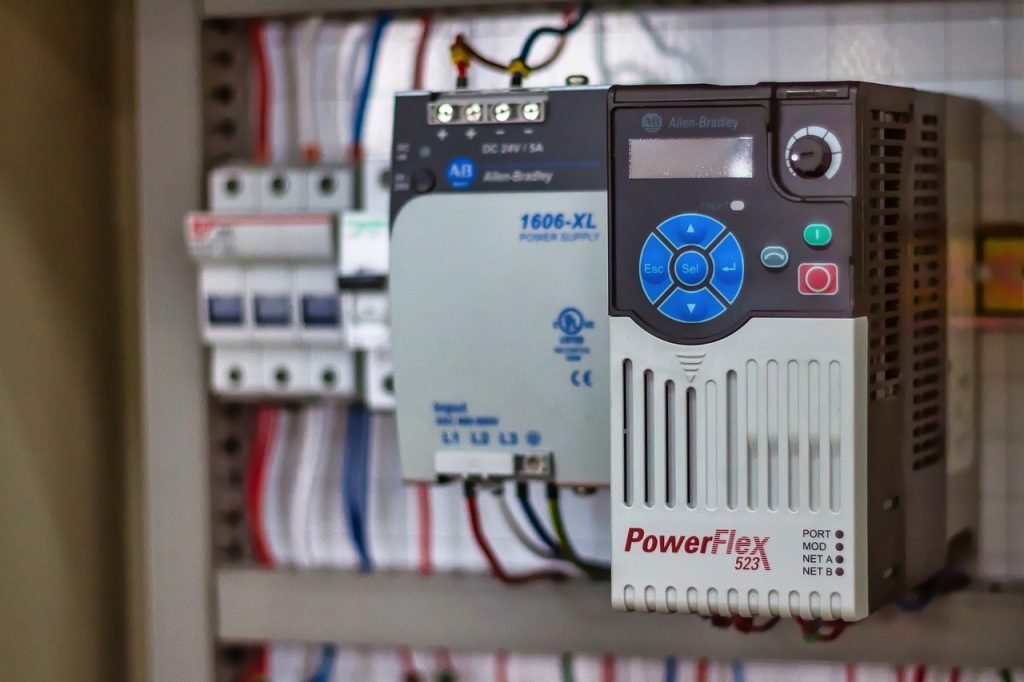
Allen-Bradley PowerFlex 40P Drive - Industrial Control

PowerFlex 40P: Essential Motor Control for Automation

Optimizing Motor Control: Why the Allen-Bradley PowerFlex 40P is Key for Industrial Automation

The Allen-Bradley PowerFlex 40P series is a highly reliable and efficient motor control solution. It delivers exceptional performance across many industrial applications. From basic localized systems to complex, medium-scale operations, this drive ensures consistent output. It offers flexible power options, advanced I/O, and intelligent communication capabilities. Therefore, the PowerFlex 40P provides a strategic balance of power, versatility, and affordability. Plant managers and OEMs value its compact, rugged design for managing pumps, conveyors, and general machinery. This drive truly simplifies factory automation.

Allen-Bradley PowerFlex 40P Drive - Industrial Control

Flexible Power for Diverse Industrial Applications

The PowerFlex 40P supports a wide array of voltage classes and horsepower ratings. This broad compatibility helps facilities streamline their drive inventory. As a result, standardizing control systems becomes much simpler.

Low Voltage (200–240V AC): These drives range from 0.4 to 7.5 kW (0.5 to 10 HP). They handle 2.3 to 33 Amps. These units are perfect for small machines and localized motor control.

Mid-Range Voltage (380–480V AC): Power options cover 0.4 to 11 kW (0.5 to 15 HP). They draw 1.4 to 24 Amps. This makes them ideal for mid-range operational needs.

High Voltage (500–600V AC): These robust models offer 0.75 to 11 kW (1 to 15 HP). They manage 1.7 to 19 Amps. Moreover, they suit high-demand equipment like pumps and compressors.

Author’s Comment (Powergear X Automation): In an era where the cost of capital equipment is rising, an engineer must select a drive that matches the load exactly. This series allows for precision selection, avoiding the common mistake of over-specifying power and increasing project costs unnecessarily. This design philosophy aligns perfectly with lean industrial automation practices.

Advanced Input/Output Enhances PLC Integration

The PowerFlex 40P supports extensive I/O configurations. This reduces the need for external relays and complex panel wiring significantly. Therefore, system setup time is greatly reduced.

Digital Inputs: Two semi-programmable inputs simplify basic start/stop control. In addition, five fully programmable digital inputs enable deep customization for specific application logic.

Output Flexibility: Two opto outputs and a programmable Form C relay output provide critical real-time motor feedback and status.

Analog Signals: Analog input/output options (0–10V or 0–20mA) are selectable via a DIP switch. This ensures accurate control signals for modern DCS and PLC systems.

These streamlined I/O capabilities simplify the process of integration. They also offer users greater flexibility when tailoring drive behavior for unique control environments.

Seamless Industrial Communication for Smart Factories

The PowerFlex 40P series supports modern industrial networks natively. This often eliminates the need for expensive, extra communication hardware.

Network Support: Optional communication cards provide native support for major protocols. This includes DeviceNet, EtherNet/IP, ControlNet, PROFIBUS DP, and LonWorks.

Remote Access: Wireless Bluetooth access is available through the DSI Wireless Interface Module (WIM). This allows for easy remote monitoring and adjustment.

As a result, seamless connectivity to PLCs and HMIs reduces engineering overhead and system downtime. This feature promotes faster commissioning and diagnostics across the factory automation layer. A 2024 IEEE report highlighted that standardized fieldbus communication shortens industrial project timelines by up to 15%.

Energy Management and Precision Feedback Control

Engineers designed the PowerFlex 40P to manage dynamic loads while improving energy efficiency. It ensures consistent motor performance at all times.

Encoder Feedback: The drive auto-detects encoder feedback with 5V, 12V, or 24V DC line driver signals. This enables highly accurate speed and position control.

Smooth Operation: Moreover, PWM frequency can reach 250 kHz. This ensures very smooth and acoustically quiet operation.

Power Reliability: Ride-through functionality uses half-DC bus operation. This is critical for keeping motors running during brief power disturbances.

Energy Sharing: DC bus sharing and pre-charge control improve energy utilization. This is particularly effective across multiple drives in shared bus systems.

These energy-conscious features are key for facilities focused on achieving sustainability goals.

Built for Durability in Harsh Industrial Environments

The PowerFlex 40P series features an engineered design for durability and operational flexibility. It performs reliably in challenging field conditions.

Braking Capacity: Integrated brake resistors support rapid load deceleration. This is essential for safe operation in hoisting and high-speed conveyor applications.

Thermal Resilience: Compact frames, such as the 22D-B3P0N104, operate without extra cooling up to 50°C ambient temperatures.

Mounting Versatility: It offers flexible mounting options, including DIN rail. Enclosure ratings range from NEMA 1/IP30 to NEMA 4/IP66.

For heat-sensitive or space-constrained setups, the PowerFlex 40P offers a high-performance drive in an efficient package. This minimizes the footprint required in crowded control panels.

Versatile Motor Control for Complex Motion Profiles

The PowerFlex 40P supports both open-loop and closed-loop control methods. This gives users flexibility for various motion control requirements.

Precision Control: Closed-loop control with encoder feedback allows for high-precision speed regulation.

Motion Sequencing: Local Position Control (StepLogic) supports basic motion profiles. The drive can store up to eight steps internally.

Smooth Transitions: Zero-cross performance optimization ensures smooth motion transitions in bipolar mode.

Reference Inputs: Multiple speed references can come from analog signals or network commands. This is invaluable for coordinated drive groups in complex control systems.

These built-in features allow the drive to handle everything from basic V/Hz control to more complicated positioning tasks without expensive, external components.

Featured Applications: Real-World Solution Scenarios

The PowerFlex 40P is suitable for numerous applications across industrial automation. Here are two prime examples:

Case 1: HVAC System Optimization (Allen-Bradley 22D-B012N104)

This model operates on 208–240V AC 3-phase power. It provides 3 HP (2.2 kW) and 12 Amps of output current.

Key Features: It includes robust PID control with auto-tuning, transient protection, and integrated dynamic braking. Setup for general-purpose use is simplified.

Best Use: This unit is ideal for cost-effective motor control in small-scale applications. Think of it in HVAC systems, light conveyors, and pump stations. Its reliability and energy efficiency are critical for these uses.

Case 2: High-Demand Material Handling (Allen-Bradley 22D-B033F104)

This model runs on 240V AC 3-phase power. It delivers 10 HP (7.5 kW) and 33 Amps of output.

Key Features: It features RS485 communication, StepLogic for sequencing, and enhanced diagnostics via a 4-digit display and 10 LED indicators. Moreover, it supports Zero Stacking and DIN rail mounting.

Best Use: This is perfect for high-inertia loads and medium-to-high-demand industrial applications, such as mixers and bulk material handling. Its enhanced diagnostics ensure maximum uptime in critical processes.

Final Thoughts: The Strategic Choice for Drive Optimization

The Allen-Bradley PowerFlex 40P series is a highly strategic investment for industrial teams. It allows them to optimize motor control performance without overspending. Its robust feature set, flexible power ranges, and compact form factor meet critical requirements for value and reliability. The 40P delivers dependable operation and built-in intelligence, satisfying the high demands of both maintenance professionals and design engineers.

If you are looking for in-depth technical guides, training, or tailored system integration for your PowerFlex drives, we invite you to explore the expertise offered by Powergear X Automation.

Click here to find your next automation solution: https://www.powergearx.com/

Frequently Asked Questions (FAQ)

Q1: What is the main operational advantage of using the PowerFlex 40P over a standard V/Hz drive in a pumping application?

A: The primary advantage lies in the closed-loop control capability, particularly its PID function and encoder feedback support. A standard V/Hz drive simply controls voltage and frequency. However, the 40P can precisely adjust its output based on real-time process feedback (like pressure or flow). This provides stable process control and ensures the pump runs at the optimal speed for energy savings, which a basic drive cannot achieve.

Q2: My facility uses an older DeviceNet network. How easily can the PowerFlex 40P integrate without major upgrades?

A: Integration is straightforward. Unlike some modern drives that only offer native EtherNet/IP, the PowerFlex 40P explicitly supports optional communication cards for older fieldbuses, including DeviceNet and ControlNet. You simply install the appropriate card, and the drive becomes a native node on the existing network. This is a massive benefit for brownfield upgrades, preventing the need for costly and disruptive network overhauls.

Q3: I am an OEM building small, heat-sensitive machines. What is your experience with the drive’s thermal performance?

A: Based on our experience, the PowerFlex 40P’s ability to run up to 50°C ambient without derating (for the compact frames) is a significant design strength. This high thermal tolerance, coupled with Zero Stacking capability, means you can place the drives right next to each other in a small, sealed panel without the usual concern of a heat-related fault trip. This translates directly to a smaller overall machine footprint and reduced panel cooling costs.

Bently Nevada 3500/22M TDI Evaluation for Industrial Automation

Bently Nevada 3500/22M TDI Evaluation for Industrial Automation

Evaluating Your Bently Nevada 3500/22M TDI: Replacement vs. Reconfiguration in Industrial Automation

The Bently Nevada 3500 Machinery Protection System is a cornerstone of critical asset monitoring in heavy industry. At its core, the 3500/22M Transient Data Interface (TDI) acts as the central nervous system. This module is vital for configuration management, transient data capture, and communication within complex industrial automation and control systems. When operational issues arise, maintenance engineers face a crucial decision: Is this a simple fix via reconfiguration, or does the TDI require a full replacement? Making the wrong call leads to unnecessary downtime and increased costs, impacting overall factory automation efficiency.

Bently Nevada 3500/22M TDI Evaluation for Industrial Automation

The Critical Role of the 3500/22M TDI in Machine Protection

The TDI is more than a simple gateway; it is the data traffic controller for the entire rack. Its primary duties include storing the rack configuration, managing high-speed data transfer to System 1 condition monitoring software, and ensuring reliable Modbus TCP/IP and Ethernet communications. Moreover, it coordinates module diagnostics and provides essential time synchronization. Because its function is so pervasive, any error in this module directly compromises the integrity of machine protection. Therefore, a structured diagnostic approach is essential for maintaining reliable PLC and DCS integration environments.

Symptoms Suggesting a Simple Reconfiguration is Sufficient

  • Many common TDI issues stem from software glitches or data integrity problems, not hardware failure. When you observe these symptoms, a simple configuration reload or firmware update is typically the most effective solution:
  • Intermittent Communication Failure: The system may experience occasional Modbus drops or System 1 connection losses. This often presents as data timeout warnings. Crucially, the TDI’s front-panel LEDs remain green, and no hard fault lights appear.
  • Configuration Integrity Errors: Look for “Configuration Not Valid” messages or issues during upload/download with the 3500 Configuration Software. These errors usually follow an interrupted transfer or an improper configuration change.
  • Firmware Mismatch and Corruption: If the TDI was recently updated, or if rack modules and the TDI have mismatched firmware versions, communication warnings are common. Reloading the firmware often resolves these versioning inconsistencies.
  • Temporary Recovery After Power Cycling: If cycling the rack power temporarily restores full operation, the underlying hardware is generally sound. The issue is likely a software lock-up or memory error, a scenario often remedied by a re-initialization process.

Clear Indicators That a TDI Replacement is Necessary

Hardware failures are definitive and cannot be resolved with software fixes. If your TDI exhibits the following signs, prepare for a full module replacement to restore system functionality:

Hard Fault Indicators on the Module: The presence of a continuously illuminated red “Module Fault” LED, or a red “OK” LED, signals a severe internal component failure. Also, if all LEDs remain off after powering the rack, internal power supply or circuit damage is suspected.

Irrecoverable Communication Hardware Failure: This means the Ethernet port is physically non-functional. The link lights on both ports will not illuminate, even after verifying cables and network switches are working. The module is detected, but it cannot physically transmit or receive data.

Failure Persistence After Full Diagnostic Sequence: If you have attempted a firmware reload, a configuration reload, and a rack power cycle, and the module still fails system diagnostics, hardware degradation is highly likely.

Thermal or Power-Related Failures: Visible signs such as a burnt smell, PCB discoloration, excessive overheating, or random, continuous resets despite stable power indicate a failure in the internal voltage regulator circuitry. According to industry data, aging voltage regulators are a common failure point for modules over ten years old.

A Field-Proven 5-Step Diagnostic Workflow

Engineers at Powergear X Automation recommend this structured approach to swiftly differentiate between software and hardware problems:

  • Check the TDI’s Front-Panel LEDs:
  • Green: Proceed with configuration and firmware checks.
  • Red or Off: Halt software attempts; prepare for replacement.
  • Verify Communication Recovery Attempts: Try swapping cables and connecting directly with a laptop. If the link restores, the issue is external (network).
  • Reload the Configuration File: Upload the current file and immediately re-download it back to the rack. This corrects common configuration inconsistencies that lead to instability.
  • Update or Reinstall the Firmware: A fresh firmware installation can resolve subtle memory or instruction set corruption.
  • Test System After Rack Power Cycle: If the module fails diagnostics immediately after the rack is fully powered up and re-initialized, the fault is almost certainly hardware-based.

Author’s Insight: When Proactive Replacement is Smart

While cost is always a factor, a proactive replacement can be the better long-term strategy for critical assets. The 3500/22M TDI plays an active role in transient data capture, which is essential for detailed diagnostics. If your TDI has served for over a decade, or if your site experiences repeated, inexplicable rack-wide communication issues, consider an upgrade. IEEE reliability standards often suggest a Mean Time Between Failures (MTBF) reduction after ten years of continuous operation, especially in harsh environments. The cost of a spare module is negligible compared to the financial impact of unplanned shutdown of a critical turbomachinery train. Maintaining a spare TDI in inventory is a standard best practice in DCS and PLC environments.

Technical Best Practice Checkpoints

  • Firmware Alignment: Ensure the TDI firmware version is fully compatible with all installed I/O modules (e.g., 3500/42M).
  • Voltage Stability: Use a multimeter to verify stable rack power supply output if random resets occur.
  • Direct Connection: When troubleshooting, always bypass network infrastructure by connecting directly to the TDI Ethernet port for a reliable communication test.
  • Transient Buffer: Unreliable transient capture in System 1 is a strong indicator of an aging TDI communication processor.

Case Study: Addressing Chronic Data Loss

A petrochemical plant running an older 3500 rack began experiencing intermittent gaps in vibration data sent to System 1. The module lights were all green, suggesting a configuration problem. However, multiple configuration and firmware reloads failed to solve the chronic data loss, indicating the communication issues were not being corrected at the software level. The engineers decided to replace the 3500/22M TDI. Post-replacement, the data stream became instantly stable, confirming a low-level hardware component—likely the Ethernet PHY chip—was degrading and causing packet loss without triggering a hard fault. This averted a potential loss of critical machine data.

Frequently Asked Questions (FAQ)

Q1: How can I definitively rule out the network before blaming the TDI for communication issues?

The simplest way is to connect a laptop with the 3500 Configuration Software directly to the TDI’s Ethernet port using a cross-over or straight-through cable (depending on the model). If you achieve a stable, continuous connection and can communicate with the module, the network infrastructure (switch, patch panel, cable run) is the source of the problem. If the direct link is unstable, the TDI hardware is the suspect.

Q2: My TDI is over 12 years old but appears to be working. Should I replace it anyway?

While continuous operation is a good sign, an older module, especially one that handles transient data, is operating on borrowed time. Industry experience shows that passive components (capacitors, resistors) degrade over time, affecting signal integrity and power regulation. A proactive replacement prevents an unplanned failure, which is almost always more expensive than a scheduled replacement. Keep the old module as a low-priority, non-critical spare or consider it for immediate disposal.

Q3: What’s the most common configuration error that mimics a TDI hardware failure?

The most common and confusing error is a version mismatch between the rack configuration file and the firmware loaded on the TDI. If the file was created with an older software version or the rack I/O modules were updated but the TDI wasn’t, the TDI will often become unstable, dropping communication. Always ensure your configuration software, rack firmware, and System 1 version are all compatible before concluding a hardware failure.

For more in-depth solutions, training, and spares for your Bently Nevada 3500 systems and to improve your overall industrial automation strategy, we invite you to explore the resources available at Powergear X Automation.

5-Step Servo Drive Troubleshooting Guide

Servo Drive Repair vs. Replacement in Industrial Automation

Overview

Servo drives are the unsung heroes of precision manufacturing, providing the speed and accuracy necessary for robotics, CNC machinery, and high-speed packaging lines.When a drive malfunctions, production grinds to a halt quickly. Whether your facility relies on a Mitsubishi MR-J2S, Yaskawa SGDH, or FANUC A06B series drive, fast and effective troubleshooting is crucial. A systematic approach determines the difference between a fleeting inconvenience and a costly, extended shutdown. This expert guide walks you through a structured, five-step diagnostic process. We highlight common brand-specific failure signatures. Finally, we provide clear criteria for deciding whether to repair, replace, or escalate the issue within your factory automation system.

Step 1: Systematically Identify Failure Symptoms

Before reaching for a multimeter or a manual, you must gather detailed, observable symptoms. Simply noting “drive fault” is insufficient for accurate diagnostics. Specificity saves time.

Observable Indicators:

A specific alarm or fault code appears on the drive’s display.

The motor is completely unresponsive or exhibits erratic, jittering movement.

Motion unexpectedly stops mid-cycle, disrupting the PLC sequence.

A distinct burnt odor is present, or the drive housing feels excessively hot.

The drive shows no display and has no power indicator lights.

Pro Tip from the Field: Document the exact drive model number and the displayed alarm code immediately. Moreover, record the system’s behavior just before the failure. This information is vital for accurately isolating the root cause and defining the next course of action.

Step 2: Eliminate External Factors First (Power and Wiring)

In industrial automation, internal drive failures account for fewer issues than external problems. Before investigating complex fault codes, eliminate the simplest, most common external causes first.

Fundamental Electrical Checks:

Verify Input Voltage: Use a true RMS multimeter to confirm the drive receives the correct input voltage at the terminals.

Inspect Connections: Check all cables and terminals for loose connections, corrosion, or signs of arcing and heat damage.

Check for Shorts/Ground Faults: A short circuit in the motor winding or cabling often triggers immediate drive overcurrent alarms.

Powergear X Automation Insight: We estimate that over 40% of all reported “drive faults” are resolved by simply correcting power or wiring issues. For instance, on a Yaskawa SGDH drive, an A.C. alarm frequently points to a shorted output or incorrect motor wiring. Therefore, always confirm good grounding, especially on older legacy systems like the Mitsubishi MR-J2S, after any maintenance.

5-Step Servo Drive Troubleshooting Guide

Step 3: Interpret Drive Alarm Codes and Fault History

Servo drives incorporate sophisticated self-diagnostic capabilities. The alarm or fault code displayed on the panel is your most important clue. Different brands use distinct codes for similar failures.

Key Fault Codes by Brand:

Mitsubishi MR-J2S:

  • AL.37: Indicates Overcurrent during deceleration—often a mechanical issue or tuning problem.
  • AL.33: Points to an Encoder error—a feedback problem.

No Display: Often suggests a blown fuse or power board failure.

Yaskawa SGDH:

  • A.C.: Output short circuit—check motor/cable integrity.
  • A.E.: Overvoltage—frequently caused by poor regeneration handling.

Solid Red LED: Indicates a severe internal hardware failure.

FANUC A06B:

  • AL-1: Overcurrent—a common indication of a shorted load or motor.
  • AL-3: Regenerative error—the drive cannot dissipate energy effectively.
  • No LED: Suggests an issue with the control or power board.

Expert Tip: Many modern drives and even some legacy control systems store a fault history log. Reviewing this log helps identify patterns. In addition, recurring errors suggest environmental factors like heat, vibration, or unstable input power.

Step 4: Isolate the Problem to the Motor or the Drive

The servo drive and motor operate as a synchronized, closed-loop system. A fault originating in the motor (e.g., a shorted coil or a damaged encoder) will cause the drive to trip, masking the true source.

Motor Testing Methods:

  • Known-Good Swap: The quickest diagnostic method is temporarily swapping the suspect motor with a functional, known-good spare unit.
  • Electrical Verification: Perform a Megger test to check for shorts to ground and use a multimeter to confirm equal resistance across all motor phases.

Brand-Specific Motor Failure Notes:

  • MR-J2S: Encoder feedback problems are prevalent. Always check the integrity of the encoder cable and connector pins.
  • SGDH: Persistent A.E. or A.C. alarms often require checking for open or shorted motor windings.
  • A06B: Motors with shorts to the ground are a leading cause of damage to the power output section of the drive.

Solution Scenario: If on-site motor testing is impractical, specialized facilities offer bench testing and joint drive-motor evaluations to diagnose system interaction issues accurately before further equipment is damaged.

Step 5: Make the Informed Decision: Repair, Replace, or Retest

Downtime is costly. Your final decision—repair or replace—must balance cost-effectiveness against required recovery speed. Statista data shows that the cost of unplanned downtime in manufacturing can exceed $10,000 per hour.

ActionJustification
Repair the DriveThe failure is clearly internal (e.g., blown component). The model is obsolete or legacy (like MR-J2S) and expensive to replace. A cost-effective fix is needed, and you can tolerate a few days of turnaround time. You must retain the original application settings or custom wiring.
Replace the DriveThe same fault has recurred multiple times. There is visible, catastrophic damage (burned components, cracked boards). Immediate recovery is mandatory to prevent production line delays. You are actively upgrading the control systems to newer, supported models.
Retest or EscalateThe fault is intermittent or only happens under high load. You have replaced the drive, but the problem persists. You strongly suspect external factors like EMI or grounding issues.

Powergear X Automation offers trusted, warranty-backed repair services for legacy and current industrial automation components, including the MR-J2S, SGDH, and A06B series.

Final Thoughts: Minimizing Downtime in Motion Control

Troubleshooting a servo drive failure is manageable when you follow a structured, step-by-step methodology. By systematically checking power, wiring, fault codes, and the motor condition, maintenance teams can quickly isolate the true issue. This allows for a pragmatic decision regarding repair or replacement, minimizing the overall impact on production.

Powergear X Automation helps manufacturers maintain continuous operation by providing essential services:

Thousands of in-stock servo drives for immediate replacement.

Trusted, expert repair services for obsolete and current models.

Fast turnaround and same-day shipping on critical spares.

Don’t let a drive failure dictate your production schedule.

Need expert support, quick diagnostics, or a rapid replacement for your industrial automation components? Contact our certified team today. Click the link to explore our solutions: Powergear X Automation

Frequently Asked Questions (FAQ)

Q1: What is the significance of the “No Display” fault on a Mitsubishi MR-J2S drive, and what should I check first?

A: A “No Display” on the MR-J2S typically signifies that the low-voltage control power supply on the drive’s power board has failed. Before concluding the drive needs repair, always check the incoming control voltage fuse. If the fuse is intact, the failure is usually internal (e.g., a power supply circuit failure), requiring the unit to be sent to a dedicated repair center.

Q2: My Yaskawa SGDH drive trips on an “A.E.” (Overvoltage) alarm only when the machine decelerates quickly. Why is this happening?

A: This is a classic symptom of a failure in the regenerative circuit, which handles the energy fed back from the motor during deceleration. The drive is unable to dissipate this energy, causing the DC bus voltage to spike. The issue could be a faulty internal braking transistor, a failed external braking resistor unit (if used), or incorrect wiring to the external resistor. Check the resistor’s continuity and connections, as this is a more common point of failure than the drive’s internal components.

Q3: We have recurring encoder errors (AL.33 on MR-J2S) after a major machine vibration event. Can I fix this without replacing the drive or motor?

A: Recurring encoder errors, especially after a physical shock, suggest mechanical damage or a connection problem, not necessarily a motor coil failure. First, meticulously check the encoder cable and its connector at both the motor and the drive end for any bent pins or abrasions in the shielding. If the error persists, the encoder head or disk inside the motor is likely misaligned or damaged. Replacing the motor’s encoder unit or the entire motor is usually the required course of action, as internal encoder repair on-site is difficult.

HMI SCADA

Industrial Automation Systems: IIoT, Hybrid-Cloud & Predictive Analytics

The Evolution of Control Systems: Beyond Simple Monitoring

Factories no longer view Human-Machine Interfaces (HMIs) and Supervisory Control and Data Acquisition (SCADA) systems as mere display panels. They were once simple windows showing if a motor was running or a valve was closed. Today, these control systems operate as the nerve center of modern industrial facilities. Their function has shifted from basic data visualization to sophisticated analysis, prediction, and seamless integration across the enterprise. This transformation is driven by several powerful trends: the rise of Industrial IoT (IIoT), the adoption of hybrid-cloud technology, advanced analytics, and the crucial requirement for IT/OT convergence. At the core of this shift are new SCADA platforms and HMIs that are smarter, incredibly intuitive, and deeply embedded in daily operational decisions. Powergear X Automation supports this critical market evolution. We provide cutting-edge HMI panels and essential components from trusted industry leaders such as Allen-Bradley, Siemens, and Mitsubishi, empowering plants to sustain a competitive edge.

Leveraging IIoT for Real-Time Operational Visibility

The Industrial Internet of Things (IIoT) completely changes how operators interact with HMIs and SCADA. Systems now display much more than simple on/off status. They integrate massive sensor data streams from every machine across production lines. This provides real-time visibility into crucial metrics like overall performance, product quality, and critical energy consumption. For instance, pairing a robust Siemens Comfort Panel with an S7-1500 PLC allows operators to instantly visualize energy trends specific to each asset. This proactive insight helps managers eliminate inefficiencies long before they become expensive cost overruns. Furthermore, the Allen-Bradley PanelView family offers seamless connectivity with ControlLogix and CompactLogix PLCs, creating unified dashboards for all critical Key Performance Indicators (KPIs).

Enhanced Anomaly Detection: Teams spot minor issues faster.
Performance Benchmarking: Compare machine or shift efficiency easily.
Integrated Data Flow: Connect floor data with MES/ERP for smarter, business-level decisions.
HMI SCADA

Hybrid-Cloud SCADA: The Best of Both Worlds

Historically, SCADA systems ran on local, on-premise servers. While reliable, this architecture severely limited scalability and secure remote access. Hybrid-cloud architectures provide an intelligent compromise: reliable local control paired with the inherent flexibility of the cloud. This design enables secure remote monitoring, much easier system scaling, and enhanced resilience against system failures. Plants can implement modernization in phases. They keep extremely latency-sensitive control functions on-premise while utilizing cloud services for global fleet dashboards, multi-site reporting, and secure data backups. Mitsubishi GOT2000 panels, for example, are perfectly suited for integration with secure remote-access tools, which extends operational visibility beyond the physical plant walls.

Proactive Maintenance Powered by Predictive Analytics

The future of SCADA is defined by being proactive, not reactive. Analytics models are now actively flagging subtle patterns that indicate an impending failure, moving beyond just waiting for an alarm to trip. This allows maintenance teams to plan necessary interventions long before a catastrophic breakdown forces production to stop. Consider a PanelView dashboard that displays subtle vibration trends on a critical motor. Connected advanced analytics can identify minor bearing wear several weeks in advance. This crucial heads-up enables perfectly planned downtime and efficient, smarter parts staging.

Minimize Unplanned Downtime: Early warning indicators provide critical lead time.
Optimize Repair Costs: Fixing issues before minor damage escalates into systemic failure.
Streamline Inventory: Better prediction of parts needs optimizes scheduling and inventory levels.

In the face of volatile supply chains and increasing budget pressures, adopting predictive maintenance is not merely an option—it is an absolute necessity for competitive operations.

Intuitive HMIs: Role-Based and Mobile-Optimized Design

The era of confusing, monochrome screens and overwhelming alarm notifications is ending. Modern HMIs prioritize clean, role-based views. These new interfaces emphasize superior usability and mobility. They ensure that operators can take action faster while minimizing the potential for human error.

Modern Touch Interfaces: Multi-language support shortens training time.
Role-Specific Dashboards: Eliminate screen clutter and highlight only actionable KPIs.
Native Mobile Support: Supervisors securely monitor real-time status using tablets or smartphones.

High-performance options include the Allen-Bradley PanelView 5310 for tight, efficient integration with Logix controllers. Similarly, Siemens Comfort Panels offer highly customizable and flexible screen layouts suitable for diverse applications.

Cybersecurity as a Fundamental Design Requirement

As connectivity expands, so does the security risk landscape. Today’s HMI/SCADA platforms must incorporate security-first features. These features include robust encrypted communications, strict role-based access controls, multi-factor authentication, and sophisticated anomaly detection tools. The primary goal is always to protect operational uptime.

The Mitsubishi GOT2000 series provides user authentication and precise access control directly at the panel level.

Furthermore, engineering environments from all major vendors now centralize security settings. This approach significantly reduces the risk of “configuration drift.” As we move deeper into Industry 4.0, security is no longer an optional add-on; it is an integrated design principle.

IT/OT Convergence: A Unified Operational Strategy

The rigid division between Operational Technology (OT) and Information Technology (IT) is rapidly disappearing. Modern SCADA and HMI platforms must natively connect with higher-level business systems. This integration allows leaders to align real-time production status with critical supply chain, quality, and financial data.

Unified Visibility: Track performance from the machine line all the way to enterprise-level KPIs.
Agile Response: Implement faster reactions to sudden supply-chain shortages or shifts in demand.
Enhanced Collaboration: Promote stronger working relationships between IT and controls engineering teams.

The crucial practical takeaway: Select HMIs and controllers that use communication standards compatible with your existing business systems. Plan your network and security architectures with IT/OT convergence as the central objective.

Conclusion: Building a Resilient Future with Smart SCADA

The current generation of industrial automation systems is shaped by powerful forces: deep IIoT integration, flexible hybrid-cloud deployments, sophisticated predictive analytics, highly modern interfaces, fundamental cybersecurity, and IT/OT convergence. These factors together are fundamentally redefining how today’s factories operate and compete globally.

Ready to accelerate your plant’s digital transformation?

Powergear X Automation can expertly assist you in evaluating your options, quickly sourcing in-stock panels, and ensuring fast shipment of components from top brands.

Click here to explore our wide range of HMI and SCADA solutions at Powergear X Automation and take the essential next step toward smarter, more resilient factory automation.

Application Scenario: Optimized Pump Station Monitoring

A municipality uses a Powergear X Automation solution to monitor remote water pump stations. Instead of sending technicians to check pumps weekly, a Siemens Comfort Panel acts as the local HMI, sending pump vibration and energy data via a secure, low-latency hybrid-cloud connection to a central SCADA system. The system uses a predictive model to alert maintenance 3-4 weeks before a pump bearing is expected to fail. This enables a shift from costly emergency repairs to scheduled, efficient component replacement during off-peak hours, dramatically reducing operational costs and unplanned downtime. This is a practical example of the Expertise and Experience we bring to real-world industrial challenges.

Frequently Asked Questions (FAQ)

Q1: How does a hybrid-cloud SCADA setup actually affect my system’s latency for critical control?

A: A well-designed hybrid-cloud architecture keeps critical, immediate control loops (like emergency stops or fast process regulation) entirely on the local PLC/DCS, guaranteeing low latency. The cloud component is used for non-critical, high-level functions like historical data aggregation, trend analysis, and remote reporting, where slightly higher latency is acceptable. The local network always retains core real-time control.

Q2: What is the single biggest operational benefit I can expect from upgrading to a modern HMI panel?

A: The most significant benefit is the reduction in human error and the increase in operator speed. Modern panels use intuitive, role-based graphics (high-resolution, customizable graphics) that reduce training time and eliminate screen clutter. This focused design means an operator can correctly identify a fault and initiate the correct response significantly faster than on an older, text-based system.

Q3: I have a mix of old and new PLCs (Allen-Bradley and Mitsubishi). Is IT/OT convergence possible without replacing everything?

A: Yes, convergence is definitely possible. It requires a strategic approach using modern middleware or specialized SCADA servers that can translate data across various industrial protocols (like Modbus, EtherNet/IP, PROFINET, etc.) and then structure that data into common IT-friendly formats (like OPC UA or MQTT). Focus on upgrading the communication gateway/SCADA layer first, rather than ripping and replacing every PLC or DCS component.

Back to Top
Product has been added to your cart