Communication Gateway vs. 4–20 mA: The Best Way to Transfer Bently Nevada 3500/42M Data to a DCS
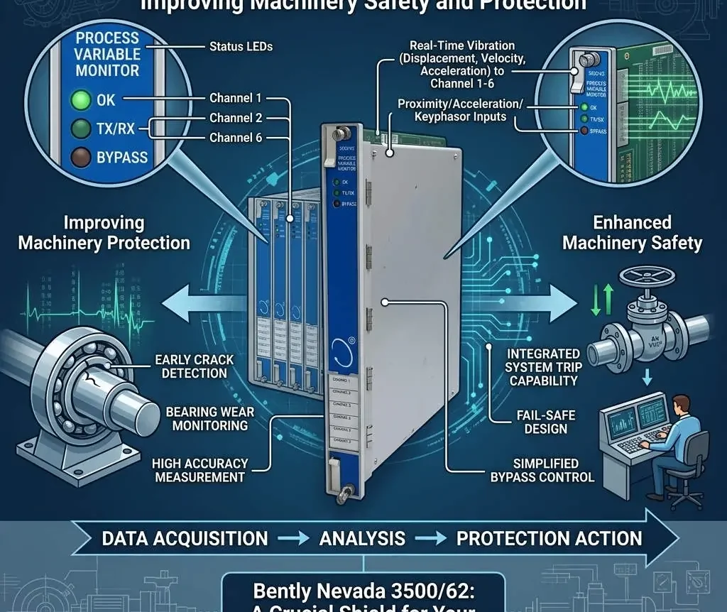
The Bently Nevada 3500/42M Proximitor/Seismic Monitor is a cornerstone of critical machinery protection in industrial automation. This robust module reliably manages vibration and position data. A critical engineering decision, however, is determining the optimal path to transmit this protection data to a central Distributed Control System (DCS). Should you rely on the legacy 4–20 mA analog output, or is a modern digital communication gateway the definitive solution?
This article, brought to you by Powergear X Automation, dissects these two options. We will explore their technical capabilities and limitations, providing a clear recommendation to support your factory automation and control systems strategy.

Understanding the Essential Data from the 3500/42M
The 3500/42M module generates complex data vital for both protection and condition monitoring. The module processes raw sensor input to provide several key metrics.
- Primary Measurement Values: This includes proximity (gap) or seismic vibration measurements.
- Processed Variables: Operators rely on calculated values like Overall Vibration, Peak-to-Peak amplitude, $1\times$ and $2\times$ amplitude components, and DC Gap voltage.
- Protection Status: Crucially, the module issues trip statuses such as OK, Alert, and Danger.
- Diagnostic Information: The module provides internal health and system diagnostic data accessible via the 3500 rack backplane.
To effectively integrate this into a DCS, the chosen method must efficiently deliver the required data points and maintain adequate update rates.
Option 1: Utilizing 4–20 mA Analog Outputs
The 4–20 mA loop represents a traditional and highly reliable method for data transfer. It converts a measured variable into a proportional current signal.
How the 4–20 mA Output Works
To use this option, the 3500 rack requires optional I/O modules, specifically the Bently Nevada 3500/92 or 3500/96 Analog Output modules. Each analog channel is configured to represent one selected variable—for instance, the overall vibration level—as a continuous 4–20 mA current signal.
Advantages of Analog Transfer
- Simplicity and Universality: The DCS or PLC (Programmable Logic Controller) requires only standard analog input cards, which are universally supported.
- Noise Resistance: The current-based signal is inherently resistant to electrical noise over long cable runs.
- Electrical Isolation: This approach offers excellent isolation between the protection system and the control system.
Limitations of Analog Transfer
However, the 4–20 mA method presents significant constraints when dealing with modern machinery monitoring needs.
- Single-Variable Constraint: You can transmit only one variable per channel. To get overall vibration and DC Gap, you need two separate analog loops.
- Data Exclusion: Alarm statuses, event data, diagnostic information, and essential waveform or spectrum data are entirely lost.
- High Wiring Complexity: A large installation requiring dozens of variables translates into a complex, costly, and resource-intensive wiring process involving numerous analog input cards.
- Resolution and Speed: The resolution is limited by the DCS/PLC analog-to-digital converter, and the update rate is relatively slow compared to digital protocols.
Use Case: Choose 4–20 mA only if you need minimal data integration, such as displaying the overall vibration value for basic trending on a DCS faceplate.
Option 2: Leveraging a Communication Gateway
For comprehensive integration and modern maintenance practices, a digital communication gateway is the superior solution. This approach transforms the protection system data into a standardized digital protocol.
How Digital Gateway Communication Works
Bently Nevada offers solutions like the 3500/95 or 3500/91 Ethernet Communication Gateway modules. These modules capture all internal data from the 3500 rack via the backplane and present it using industrial protocols like Modbus TCP/RTU, OPC UA, or other Ethernet-based standards.
Advantages of Digital Gateway Transfer
The digital gateway overcomes all the limitations of the analog approach, providing a future-proof link.
- Full Data Access: Access to all measurement parameters from every channel, not just one processed value.
- Critical Status Information: Includes all crucial data points: ✅ Alarm statuses (Alert/Danger trips) ✅ Channel OK status ✅ Configuration and system diagnostics
- High Performance: Features a high data update rate, suitable for detailed trending and fast-acting alarms.
- Scalability and Efficiency: A single Ethernet cable replaces dozens or hundreds of analog signal wires, drastically reducing installation complexity and cost.
- Monitoring Platform Support: Facilitates integration with specialized condition monitoring systems, such as GE’s System 1 platform.
Limitations of Digital Gateway Transfer
This option is not without its own requirements.
- Increased Configuration: Requires networking knowledge and protocol configuration (e.g., Modbus address mapping).
- DCS/Network Dependency: The DCS or SCADA system must natively support the chosen industrial protocol (e.g., Modbus TCP).
- Network Reliability: Performance depends entirely on the stability and reliability of the industrial network infrastructure.
Use Case: Choose a communication gateway when multiple variables are required, diagnostic integration is essential, or when transmitting a large number of measurement points.
Best Practice Recommendation and Expert Insight
In the landscape of modern industrial automation, our recommendation is decisive: The Communication Gateway is the preferred solution.
The industry trend, validated by reports from ISA and MarketsandMarkets, shows a clear shift toward digital integration for its scalability and comprehensive data access. While 4–20 mA has a place in legacy or extremely basic systems, it fails to meet the data demands of predictive maintenance and holistic asset management.
⚙️ Use 4–20 mA for:
- Minimalist Requirements: Displaying only one single, slow-changing overall value.
- Legacy Systems: Facilities where existing wiring and control systems lack networking capability.
🔧 Use a Communication Gateway for:
- Comprehensive Diagnostics: Accessing all parameters for advanced asset health monitoring.
- Efficiency and Scalability: Eliminating massive analog card and wiring infrastructure.
- Modern Standards: Integration with digital protocols in line with modern PLC and DCS architecture.
Author Comment (Powergear X Automation): Relying solely on 4–20 mA for critical machinery data is like buying a Ferrari but only using the speedometer. The true value of the Bently Nevada 3500/42M lies in its full spectrum of data—alarms, diagnostics, and multiple parameters. The communication gateway unlocks this value, making it a crucial component for maximizing machine uptime and embracing the principles of Industry 4.0.
Practical Solution Scenario: Advanced Asset Management
Imagine a large turbine package. The protection system generates eight key values (Overall, 1x, Gap, Phase) for each of the four bearings, plus two thrust position measurements.
- Analog Scenario: You would need (8 x 4) + 2 = 34 separate analog loops and 34 analog input channels on the DCS. This creates complexity and cost.
- Digital Gateway Scenario: A single Ethernet cable from the 3500/95 gateway can deliver all 34 values, plus all associated alarm statuses and diagnostic information, using only one DCS network port. This greatly simplifies wiring, reduces hardware cost, and provides richer data for sophisticated analysis in systems like GE’s System 1.
Frequently Asked Questions (FAQ)
Q1: Can I use both 4–20 mA and the Communication Gateway simultaneously?
A: Yes. Many clients choose a hybrid approach. They use the 4–20 mA output for a few primary, overall vibration values needed immediately on the basic DCS Human-Machine Interface (HMI) screen. Meanwhile, the communication gateway provides the full diagnostic dataset to a separate condition monitoring platform (System 1), effectively separating the protection and diagnostic data streams.
Q2: What is the main configuration hurdle when implementing a Communication Gateway?
A: The primary configuration challenge is accurately mapping the Modbus register addresses within the DCS or SCADA system. Each Bently Nevada variable (e.g., Overall Vibration Channel 1) corresponds to a specific register address in the gateway. This mapping must be meticulously configured to ensure the DCS is reading the correct value, requiring close coordination between the machinery protection specialist and the DCS engineer.
Q3: Does the Communication Gateway replace the need for physical relay outputs for trips?
A: No. The communication gateway is primarily for data transfer to the DCS/SCADA system. For critical machinery trip actions, the physical relay outputs (3500/32 Relay Module) must still be used. Protection systems operate independently and rapidly based on hardware logic; digital communication is too slow and network-dependent to be the primary means of shutdown protection.
To learn more about optimizing your machinery protection integration and leveraging the power of industrial communication, visit Powergear X Automation at https://www.powergearx.com/.