Over 50,000 hot-selling automation module components.
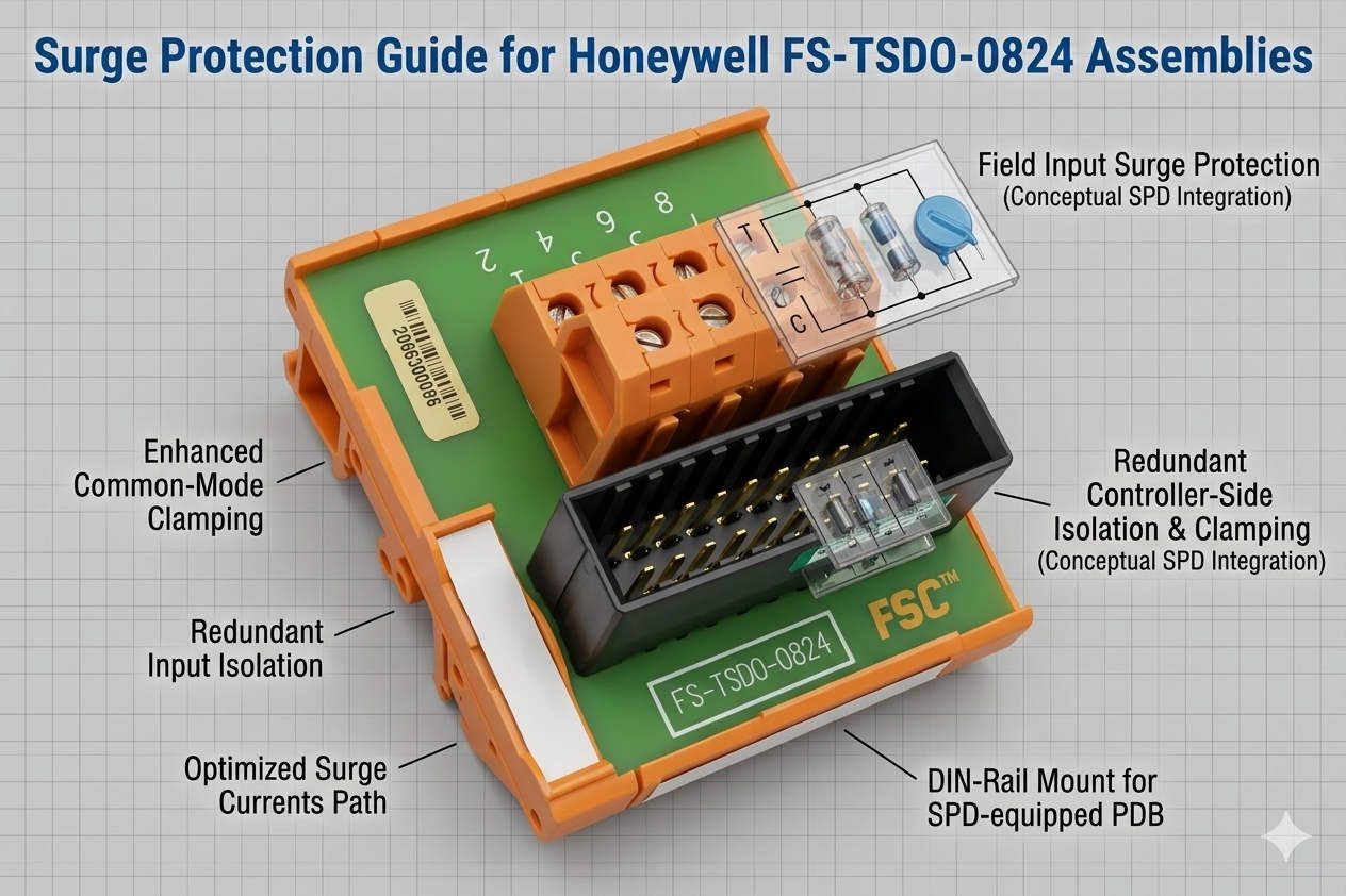
Surge Protection Guide for Honeywell FS-TSDO-0824 Assemblies

Surge Protection Guide for Honeywell FS-TSDO-0824 Assemblies

Strategic Surge Protection for Honeywell FS-TSDO-0824 Digital Output Termination Assemblies

Maximizing Reliability in Honeywell Safety Manager Architectures

The Honeywell FS-TSDO-0824 serves as a critical interface for digital output signal termination. In high-stakes environments like petrochemical plants and offshore platforms, signal integrity remains paramount. This termination assembly ensures stable communication between safety controllers and field actuators. However, the unit does not feature built-in surge suppression modules by default. Engineers must therefore evaluate external protection strategies to safeguard expensive I/O hardware from electrical transients.
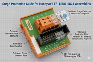
Surge Protection Guide for Honeywell FS-TSDO-0824 Assemblies

Surge Protection Guide for Honeywell FS-TSDO-0824 Assemblies

The Vital Role of Surge Mitigation in Process Automation

In modern industrial automation, transient voltage spikes represent a significant threat to control system uptime. Lightning strikes or large motor switching operations often induce high-energy surges into field wiring. These events can cause immediate hardware destruction or latent insulation degradation. Adding external Surge Protection Devices (SPD) effectively shields the FS-TSDO-0824 from inductive kickback. Consequently, facility managers see a marked reduction in unplanned shutdowns and hardware replacement costs.

Technical Considerations for External SPD Integration

Successful SPD integration requires more than just physical installation. Engineers must verify that the clamping voltage aligns with the digital output card’s tolerance. Moreover, leakage current from the SPD must remain below the field device’s threshold. High leakage can lead to “false-on” states, where valves fail to close during safety demands. Based on industry reports from MarketsandMarkets, the demand for high-reliability surge suppression is growing at a CAGR of over 5% due to increasingly sensitive electronic components.

Optimizing Grounding Infrastructure for Transient Suppression

Surge protection effectiveness depends heavily on the quality of the grounding architecture. A high-impedance ground path renders even the most advanced SPD useless. In Honeywell safety cabinets, installers should prioritize short, direct grounding conductors. Ideally, these leads should measure less than 0.5 meters. Furthermore, separate instrument grounds from power grounds to prevent noise injection. According to IEC 61643 standards, maintaining low grounding impedance is essential for diverting transient currents safely away from the FS-TSDO-0824 channels.

Managing Inductive Loads and Back-EMF Challenges

Digital outputs frequently drive inductive components like solenoid valves and interposing relays. When these loads de-energize, they generate a reverse electromotive force (Back-EMF) spike. Without proper suppression, these spikes erode relay contacts and stress electronic drivers. For DC systems, flyback diodes or TVS suppressors provide excellent protection. For AC circuits, RC snubber networks effectively reduce arcing. Implementing these layered defenses extends the operational lifespan of the termination assembly significantly.

Expert Recommendations from Powergear X Automation Limited

At Powergear X Automation Limited, we believe surge protection is a non-negotiable insurance policy for outdoor field wiring. Our field experience indicates that most I/O failures in coastal refineries stem from inadequate transient management. We recommend installing SPDs at the cabinet entry point to intercept surges before they reach internal modules. While the initial investment may seem high, the long-term savings in MTTR (Mean Time To Repair) provide a clear return on investment for any factory automation project.

Selection Guide and Practical Implementation Steps

When selecting surge protection for the FS-TSDO-0824, follow these critical steps:

  • ✅ Identify the signal voltage level (typically 24VDC for Safety Manager outputs).
  • ✅ Verify the hazardous area classification (Ex-i or non-sparking requirements).
  • ✅ Ensure the SPD response time is fast enough to protect high-speed digital logic.
  • ✅ Choose DIN-rail mounted units for easier maintenance and status monitoring.

Industrial Solution Scenarios

  • Refinery Tank Farms: Long-distance outdoor cables are highly susceptible to lightning; SPDs are mandatory here.
  • Chemical Loading Stations: Frequent motor and pump starts create high electrical noise; layered suppression prevents signal jitter.
  • Offshore Platforms: The saline environment increases corrosion; use SPDs with hermetically sealed housings and reliable status indicators.

Frequently Asked Questions (FAQ)

Q: Does adding an external SPD affect the SIL rating of a safety loop?
Technically, adding components can affect loop calculations. However, most passive SPDs have negligible failure rates. You should consult your safety functional engineer to ensure the SPD does not introduce unacceptable delay or leakage into the loop.

Q: How often should we inspect surge protectors on Honeywell systems?
We recommend an annual visual inspection and a continuity check after every major thunderstorm season. If the MOV (Metal Oxide Varistor) indicator shows thermal discoloration, replace the module immediately to maintain protection.

Q: Can I use one SPD for multiple digital output channels?
No, this is not recommended. Each output channel should have its own dedicated protection path to prevent cross-talk and ensure that a fault in one field device does not compromise the entire termination assembly.

Discover more technical solutions and high-quality parts at the official Powergear X Automation Limited website for your next project.
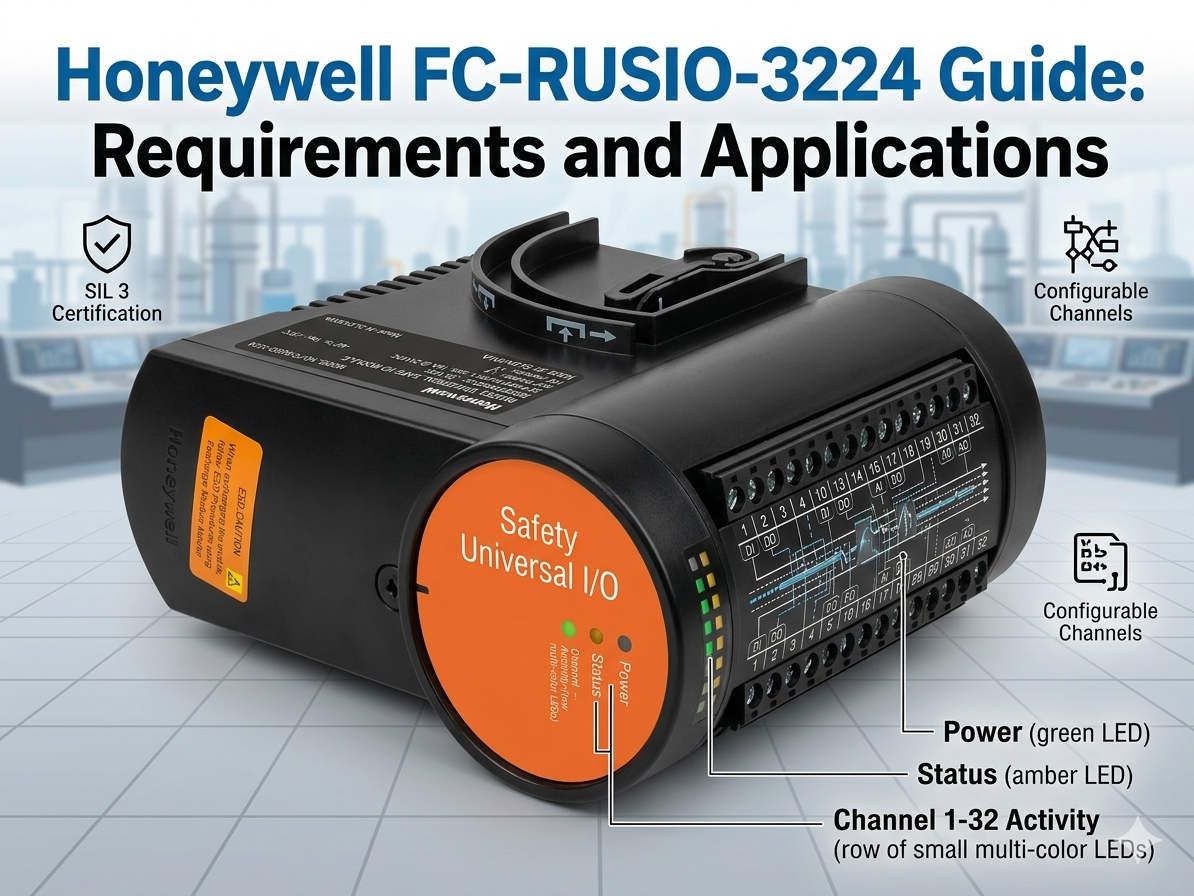
Honeywell FC-RUSIO-3224 Guide Requirements and Applications

Understanding Remote Safety I/O: Honeywell FC-RUSIO-3224 Features

Optimizing Safety Systems with the Honeywell FC-RUSIO-3224 Universal I/O Module

Understanding the Engineering Interface and Connectivity Requirements

The Honeywell FC-RUSIO-3224 stands as a sophisticated remote universal safety I/O module. Many technicians often ask if this unit requires a dedicated, standalone programming cable. Unlike traditional PLCs that utilize serial or USB leads, this module integrates directly into the Honeywell Experion PKS architecture. Engineers typically perform configuration through centralized workstations and Fault Tolerant Ethernet (FTE) networks. Consequently, physical direct-connect cables are rarely necessary for routine software deployment.

Honeywell FC-RUSIO-3224 Guide Requirements and Applications

Honeywell FC-RUSIO-3224 Guide Requirements and Applications

Core Application Value in Process-Critical Environments

Modern industrial automation demands high reliability in petrochemical, refinery, and chemical processing sectors. The FC-RUSIO-3224 excels by reducing field wiring complexity and enhancing signal integrity. By deploying distributed I/O closer to field devices, plants can significantly lower cabinet density. Moreover, this architecture simplifies brownfield modernization projects where existing conduit space is limited. Reducing the total cable load also minimizes potential points of failure within the control infrastructure.

Technical Insights into Communication and Network Topology

The communication path for the FC-RUSIO-3224 represents a shift from legacy serial protocols to high-speed networking. These modules rely on safety controller communication and dedicated configuration tools within the Honeywell environment. Therefore, installation teams must prioritize network routing and firmware alignment before hardware commissioning. In our experience at Powergear X Automation Limited, mismatched firmware revisions often cause more downtime than actual hardware defects. Ensuring software-side validation remains the most critical step for successful integration.

Environmental Reliability and Advanced Cabinet Design

Thermal management is a frequent concern in harsh refinery applications. Remote I/O modules housed in poorly ventilated enclosures often suffer from intermittent communication faults. To ensure stability, maintain consistent airflow and follow strict IEC industrial EMC grounding practices. Additionally, keep high-power VFD wiring isolated from sensitive I/O signal paths. Field data suggests that extreme temperature cycling can loosen mechanical connections, particularly in offshore or high-vibration settings.

System Compatibility and Strategic Lifecycle Management

Before procuring replacement modules, users must verify the specific system generation and firmware revision levels. Assumption of “plug-and-play” interchangeability is a common mistake in complex DCS environments. Even physically identical units may fail system validation if the database configuration does not align. In regulated industries like LNG production, documenting module substitutions is vital for audit compliance. Powergear X Automation Limited recommends keeping a detailed log of hardware revisions to streamline future maintenance windows.

Installation and Maintenance Best Practices

  • ✅ Validate Access: Confirm engineering workstation connectivity before energizing the cabinet.
  • ✅ Shielded Wiring: Use shielded twisted-pair cables in high-noise environments like turbine areas.
  • ✅ Surge Protection: Install external surge arrestors for modules connected to outdoor field instruments.
  • ✅ Grounding Protocols: Follow single-point grounding rules to prevent ground loops in communication paths.

Strategic Buyer’s Guide for Procurement Teams

Procurement departments should recognize that the FC-RUSIO-3224 is a component of a larger safety ecosystem. While a proprietary handheld cable is not standard, specific maintenance adapters may be required for deep diagnostics. Buyers should always check the existing Honeywell lifecycle support status before initiating large-scale replacements. For those seeking reliable inventory and technical support, we invite you to explore the solutions at Powergear X Automation Limited, where we specialize in high-demand industrial hardware.

Industrial Application Scenarios

  • Petrochemical Refineries: Managing safety-instrumented functions (SIF) with high-density universal I/O.
  • Chemical Processing: Reducing wiring costs in modular “skid” based manufacturing units.
  • Oil & Gas Wellheads: Providing ruggedized remote monitoring in geographically exposed locations.

Frequently Asked Questions (FAQ)

Q: Can the FC-RUSIO-3224 be configured without the Honeywell Experion software?
No, this module is an integrated component of the Honeywell safety environment. It requires the authorized engineering tools and system database to define channel types and safety parameters.

Q: How does this module handle different signal types like AI, DI, or DO?
The “Universal” designation means each of the 32 channels is software-configurable. This flexibility allows one hardware part number to support various field devices, simplifying spare parts inventory.

Q: What is the most common cause of communication failure on these modules?
In my professional experience, network switch configuration and improper shield grounding are the primary culprits. Always ensure the FTE network is properly segmented and that shielding is only grounded at the designated control end.

For high-quality industrial components and expert guidance, visit the Powergear X Automation Limited website today.

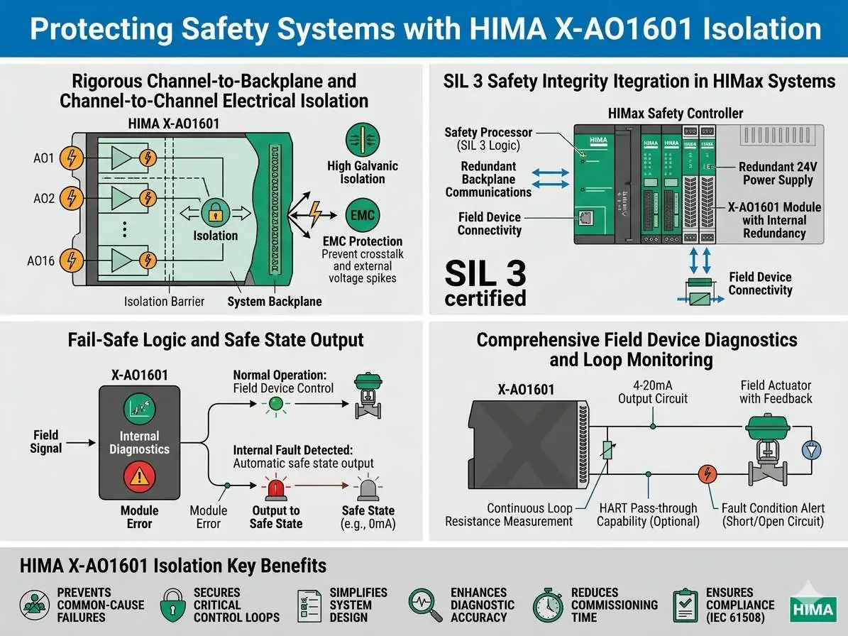
Protecting Safety Systems with HIMA X-AO1601 Isolation

HIMA X-AO1601 Analog Output Module Technical Guide & Specs

Maximizing Safety System Integrity with the HIMA X-AO1601 Analog Output Module

The Role of HIMA X-AO1601 in Safety-Critical Control Systems

The HIMA X-AO1601 analog output module plays a vital role in modern industrial automation. It supports high-integrity processes in oil and gas, chemical processing, and pharmaceutical sectors. This module ensures stable signal transmission while preventing electrical faults from spreading throughout the system. Consequently, it maintains operational continuity even in demanding environments. Engineers prioritize this model for its ability to handle sensitive control loops with extreme reliability.

Protecting Safety Systems with HIMA X-AO1601 Isolation

Protecting Safety Systems with HIMA X-AO1601 Isolation

Understanding Channel Isolation Architecture and Signal Integrity

The X-AO1601 features advanced galvanic isolation between individual channels and the backplane. This design choice effectively eliminates ground loops in large distributed control systems (DCS). Moreover, it ensures that noise on one loop does not interfere with adjacent signals. In multi-loop PID systems, this isolation prevents oscillations often misidentified as tuning errors. Therefore, it provides the precise analog control necessary for valve positioning and dosing applications.

Technical Realities of Short-Circuit Protection Limits

While the module demonstrates high resilience, it does not include full active short-circuit protection for every channel. A hard short on the output may cause a channel shutdown or degraded performance levels. As a result, repetitive faults could shorten the operational lifespan of the hardware. We recommend adding external current-limiting resistors for applications involving long field cables. Additionally, combining the module with intrinsically safe barriers is essential in hazardous locations.

Ensuring Output Stability for High-Precision Applications

This module consistently delivers high-resolution 4–20 mA signals across broad industrial temperature ranges. High stability directly improves control precision in pressure regulation and flow dosing systems. Furthermore, it reduces signal drift over time, which lowers the frequency of required manual recalibrations. In pharmaceutical batch processing, even minor signal deviations can lead to production waste. The X-AO1601 mitigates these risks through superior hardware engineering and thermal management.

Installation Strategies for Long-Term Maintenance Reliability

Field experience shows that most electrical faults occur at terminal boxes rather than inside cabinets. Therefore, following strict installation protocols is necessary to protect the HIMA X-AO1601 module. Consider the following maintenance best practices:

  • ✅ Use fused terminal blocks to provide an extra layer of protection against field shorts.
  • ✅ Route analog cables separately from high-power lines to minimize electromagnetic interference.
  • ✅ Implement a single-point grounding scheme to prevent potential differences between cabinets.
  • ✅ Use spring-clamp terminals in high-vibration environments like offshore platforms or compressors.

Expert Commentary from Powergear X Automation Limited

At Powergear X Automation Limited, we believe the X-AO1601 represents a benchmark for safety-rated analog outputs. However, users must not mistake internal isolation for total circuit immunity. In our experience, many system failures stem from over-reliance on internal module protections. To achieve true SIL-rated reliability, you must integrate external surge protection. We advise all technical teams to verify firmware compatibility before upgrading legacy HIMA racks to ensure seamless integration.

Practical Solution Scenarios and Application Cases

  • Refinery Valve Control: Provides isolated feedback loops to ensure safe valve positioning during emergency shutdowns.
  • Chemical Dosing Systems: Delivers precise 4-20mA signals to maintain strict chemical ratios in continuous processes.
  • Pharmaceutical Manufacturing: Ensures signal accuracy for temperature-sensitive batch reactions to comply with FDA standards.

Industrial Automation Frequently Asked Questions

Q: Does the X-AO1601 remove the need for external surge arrestors in outdoor wiring?
No, external protection remains necessary. While the module is robust, long-distance outdoor cables are susceptible to lightning and transients that exceed internal isolation limits.

Q: How do I handle a channel shutdown caused by an accidental short circuit?
First, clear the field fault and check the loop resistance. You may need to cycle the power or reset the module firmware depending on your specific HIMA system configuration.

Q: Can I mix different load types on the same X-AO1601 module?
Yes, the channel-to-channel isolation allows for different loads. However, ensure that each loop stays within the module’s total power dissipation specifications to prevent overheating.

To optimize your control system with authentic HIMA components and professional support, please visit the Powergear X Automation Limited official website today.

ABB CI630 Communication Interface: Optimizing Advant OCS Networks

ABB CI630 Communication Interface: Optimizing Advant OCS Networks

Enhancing Connectivity in Advant OCS Systems: The Essential Role of the ABB CI630 Communication Interface

Establishing Stable Data Highways in Industrial Automation

The ABB CI630 communication interface module functions as a critical bridge within the Advant OCS architecture. It facilitates high-speed, deterministic data exchange between controllers, such as the AC450 or AC460, and remote I/O systems. In sectors like power generation and petrochemicals, reliable communication remains a top priority. Consequently, the CI630 ensures that field data reaches the Distributed Control System (DCS) without interruption or corruption.

ABB CI630 Communication Interface: Optimizing Advant OCS Networks

Seamless Integration via MasterBus and Advant Fieldbus Protocols

The CI630 natively supports ABB proprietary protocols, including MasterBus 300 and Advant Fieldbus. This compatibility allows engineers to integrate legacy hardware with modern nodes without costly system overhauls. Moreover, these protocols provide a deterministic environment, which is vital for closed-loop regulation and safety-critical tasks. Choosing the wrong interface for third-party hardware often leads to latency or complete communication failure. Therefore, verifying the network topology remains an essential first step in any system upgrade.

Impact of Response Time on Process Control Precision

Communication refresh rates directly dictate the effectiveness of the entire DCS scanning cycle. For high-speed processes like combustion control or chemical reactions, every millisecond matters. Lower latency results in faster alarm triggers and more stable PID performance. However, high bus loads can cause jitter, leading to intermittent control fluctuations. Many technicians mistakenly blame PID parameters for stability issues when the root cause is actually bus congestion managed by the interface module.

Engineering Resilience Against Harsh Industrial Environments

Modern factory automation requires hardware that survives extreme conditions. The CI630 design emphasizes high Electromagnetic Compatibility (EMC) and temperature resistance. It reduces bit error rates in high-interference zones like power substations. As a result, the system experiences fewer packet retransmissions and less unplanned downtime. Despite its robust build, we recommend using shielded cables and proper grounding when installing modules near variable frequency drives (VFDs) to maintain peak signal integrity.

Best Practices for Installation and Maintenance

Data suggests that over 60% of communication faults stem from improper grounding and environmental factors. To ensure long-term reliability, follow these technical guidelines:

  • ✅ Grounding Management: Implement single-point grounding to prevent ground loops.
  • ✅ Shielding Integrity: Ensure the communication cable shield connects firmly at the control cabinet side.
  • ✅ Cable Routing: Maintain a minimum clearance of 20–30 cm between communication and power lines.
  • ✅ Mechanical Security: Use DIN rail clamps and locking terminals in high-vibration areas like compressor stations.
  • ✅ Surge Protection: Install dedicated Fieldbus surge arresters for long-distance outdoor communication links.

Expert Commentary from Powergear X Automation Limited

At Powergear X Automation Limited, we believe the CI630 is more than a spare part; it is a vital asset for lifecycle management. While ABB has moved many Advant modules into later lifecycle phases, the CI630 remains a preferred choice for bridging existing infrastructure toward the 800xA platform. We often observe that “intermittent” faults are usually symptoms of aging infrastructure rather than module failure. Thus, a proactive replacement strategy for mission-critical nodes is highly recommended to avoid catastrophic production losses.

Real-World Application Scenarios

  • Petrochemical Refining: Ensuring synchronized data across multiple AC450 controllers for complex distillation processes.
  • Utility Power Plants: Providing redundant communication paths to maintain turbine control during electrical transients.
  • Continuous Manufacturing: Reducing Mean Time to Repair (MTTR) by using hot-swappable communication interfaces in active loops.

Frequently Asked Questions (FAQ)

Q: How do I know if my CI630 module requires an immediate firmware update?
If you are introducing newer AC400 series controllers into an older network, firmware mismatches often cause synchronization errors. Check the revision history; if your module is several versions behind, it may not support the latest redundancy protocols required for modern DCS stability.

Q: Can the CI630 be replaced while the system is powered on?
While the hardware may support physical insertion, we advise caution. In redundant configurations, you must verify that the secondary module has taken full control of the bus before removal. Performing a “hot standby test” during scheduled maintenance is the safest way to validate this capability.

Q: What is the most effective way to troubleshoot “Communication Timeout” errors?
Start by checking the bus terminator resistance. A missing or damaged terminator causes signal reflection. If the physical layer is intact, use a protocol analyzer to check for high bus utilization rates. Often, adding too many nodes to a single CI630 interface exceeds its optimal processing capacity.

For high-quality ABB components and expert technical support, visit the official Powergear X Automation Limited website to secure your industrial supply chain.

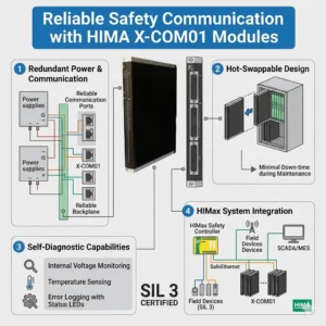
Reliable Safety Communication with HIMA X-COM01 Modules

HIMA X-COM01 Guide: Bridging SafeEthernet and Modbus TCP

Enhancing Functional Safety and Interoperability with the HIMA X-COM01 Communication Module

The Vital Role of X-COM01 in Modern Safety Architectures

The HIMA X-COM01 communication module serves as a critical bridge in high-integrity industrial environments. It connects safety-critical control systems with standard industrial networks without compromising functional safety. In sectors like oil and gas or pharmaceutical manufacturing, maintaining SIL-rated architectures is essential. This module enables deterministic data exchange while supporting both SafeEthernet and Modbus TCP protocols. As a result, engineers can achieve seamless integration between safety PLCs and higher-level monitoring systems.

Reliable Safety Communication with HIMA X-COM01 Modules

Reliable Safety Communication with HIMA X-COM01 Modules

Dual-Protocol Mastery: Balancing Safety and Openness

The X-COM01 handles SafeEthernet and Modbus TCP simultaneously to provide maximum flexibility. SafeEthernet ensures certified safety communication between HIMA controllers using advanced redundancy and CRC mechanisms. These features are vital for Emergency Shutdown (ESD) systems where data integrity is mandatory. Conversely, Modbus TCP offers interoperability with SCADA, DCS, and third-party hardware. This dual capability eliminates the need for external protocol gateways. Consequently, it reduces latency and removes potential points of failure in the network.

Optimizing Communication Latency and Determinism

In the world of factory automation, predictable response time outweighs raw transmission speed. The X-COM01 is specifically engineered for deterministic data exchange. It ensures that critical safety signals, such as trip commands, reach their destination within strict time windows. According to industry research from organizations like ARC Advisory Group, unstable latency is a leading cause of nuisance trips. Therefore, the X-COM01 provides the stability needed to maintain high plant availability and safety compliance.

Strategic Network Redundancy and Reliability

Reliability in continuous-process industries directly impacts the bottom line by preventing unplanned downtime. The X-COM01 module supports redundant communication paths within the SafeEthernet architecture. If one network path fails, the system continues to operate without interruption. However, achieving this level of reliability requires precise configuration. Misconfigured ring or star topologies often cause commissioning issues in complex control systems. Therefore, proper network design remains a prerequisite for leveraging the module’s full potential.

Professional Installation and Maintenance Best Practices

Maintaining a robust safety network requires adherence to strict engineering standards. Powergear X Automation Limited recommends the following field-proven strategies:

  • ✅ Implement Logical Segmentation: Use VLANs or dedicated switches to separate safety traffic from non-safety Modbus data.
  • ✅ Verify Shielding Integrity: Always use shielded industrial Ethernet cables in high-EMI environments to prevent intermittent faults.
  • ✅ Validate Redundancy: Physically disconnect network paths during Factory Acceptance Testing (FAT) to confirm seamless failover.
  • ✅ Monitor Environmental Factors: Ensure the control cabinet maintains proper cooling to prevent thermal stress on communication components.

Expert Analysis from Powergear X Automation Limited

At Powergear X Automation Limited, we see a clear trend toward “Safety-Integrated Openness.” The X-COM01 embodies this by allowing safety data to coexist with diagnostic monitoring. However, we believe users must remain vigilant about network security. As safety systems become more connected, robust cybersecurity measures must accompany physical hardware like the X-COM01. We recommend this module for users who need to modernize their DCS integration while maintaining strict adherence to IEC 61508 standards.

Application Scenarios and Solutions

  • Chemical Processing: Integrating reactor ESD systems with a centralized SCADA for real-time diagnostic visibility.
  • Offshore Platforms: Ensuring redundant communication between fire and gas (F&G) systems across long distances.
  • Pharmaceutical Plants: Maintaining batch traceability and safety integrity in highly regulated GAMP environments.

Frequently Asked Questions (FAQ)

Q: Can I use the X-COM01 for safety-related control of third-party VFDs via Modbus TCP?
No, Modbus TCP is not a safety-certified protocol on the X-COM01. For safety-related control (such as STO), you must use SafeEthernet between compatible HIMA devices or hardwired safety I/O for third-party hardware.

Q: What is the most common cause of “Communication Loss” alarms in new X-COM01 installations?
In our experience, most issues stem from IP address conflicts or incorrect subnet masks within the Modbus configuration. Ensure that your safety network range does not overlap with the plant-wide office network.

Q: Does the X-COM01 require special software for configuration?
Yes, configuration is typically handled through HIMA’s engineering tool (like SILworX). You must ensure your software version supports the specific firmware revision of the X-COM01 module to enable all SafeEthernet features.

To find the most reliable safety components and technical support for your next project, visit the Powergear X Automation Limited website today.

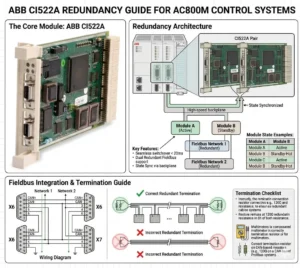
ABB CI522A Redundancy Guide for AC800M Control Systems

ABB CI522A Redundancy Guide for AC800M Control Systems

Does CI522A Support Redundancy? Implementing ABB AC800M Serial Interfaces

The Role of CI522A in Industrial Control Systems

The ABB CI522A serves as a vital communication interface within the AC800M DCS ecosystem. It provides essential serial connectivity, typically supporting RS-232 or RS-485 protocols for third-party device integration. However, engineers must understand that the CI522A does not offer native hardware redundancy. Unlike high-level Ethernet modules like the CI854A, it operates as a single-channel interface. Consequently, designers must plan for system-level availability rather than relying on module-level failover.

ABB CI522A Redundancy Guide for AC800M Control Systems

ABB CI522A Redundancy Guide for AC800M Control Systems

Technical Architecture and Communication Constraints

The internal design of the CI522A lacks dual-port circuitry or hot-standby capabilities. As a result, any failure in the module or the serial physical link causes an immediate communication loss. In critical sectors like oil and gas, this single-point failure poses a significant risk to data acquisition. Therefore, maintenance teams must prioritize external backup strategies. Industry reports suggest that while serial protocols remain relevant, their inherent lack of built-in redundancy drives the shift toward smarter gateways.

Integration with Redundant AC800M Controllers

While the module itself is non-redundant, you can utilize the CI522A within redundant PM861 or PM864 controller pairs. In this configuration, each controller hosts its own independent CI522A module. This setup maintains high availability at the controller level during a switchover. However, the field device must support dual communication paths to ensure a seamless transition. Many legacy Modbus RTU devices only allow one master, which creates a significant bottleneck in automated production lines.

Optimizing Protocol Redundancy via Modbus and Custom Serial

The CI522A primarily handles Modbus RTU and proprietary serial strings. Since Modbus RTU follows a strict master-slave architecture, achieving redundancy requires complex application-level logic. Moreover, any disruption in the master’s polling sequence can lead to device timeouts. As a result, many modern facilities deploy serial-to-Ethernet converters. This allows the system to leverage ABB’s Redundant Network Routing Protocol (RNRP) for much higher reliability than traditional serial links.

Installation Standards for High-Reliability Environments

Reliable operation starts with proper physical layer installation. Serial communication is notoriously sensitive to electromagnetic interference (EMI) and ground loops. To maintain signal integrity, follow these technical standards:

  • ✅ Use high-quality shielded twisted-pair (STP) cables for all RS-485 runs.
  • ✅ Ensure the cable shield is grounded at only one end to prevent loop currents.
  • ✅ Implement isolated repeaters to segment long daisy chains and limit failure propagation.
  • ✅ Install surge protection for any outdoor cable runs exceeding 50 meters.

Strategic Maintenance and Field Engineering Insights

From the perspective of Powergear X Automation Limited, we recommend treating the CI522A as a legacy bridge. While it is highly reliable for its intended purpose, it represents a “non-redundant edge” in your control system. If your project demands 99.99% uptime, consider migrating to Ethernet-based I/O. However, for retrofitting existing systems where downtime must be minimized, the CI522A remains a cost-effective solution for interfacing with localized analyzers and older PLCs.

Application Scenarios and Practical Solutions

  • Chemical Processing: Use dual gateways to bridge CI522A serial data into the redundant Ethernet backbone of the AC800M.
  • Power Plants: Distribute critical sensors across multiple CI522A modules to ensure that a single module failure does not blind the entire operator station.
  • Water Treatment: Leverage the CI522A for non-critical monitoring while keeping core control on redundant Ethernet modules.

Frequently Asked Questions (FAQ)

Q: Can the AC800M firmware automatically switch between two CI522A modules if one fails?
No, the firmware does not perform an automatic “bumpless” switch for serial modules. You must write specific logic in Control Builder M to detect a “Module Error” and manually redirect communication tasks to a secondary module or port.

Q: Is the CI522A compatible with all versions of the PM866 controller?
The CI522A is compatible with most AC800M controllers, including the PM866. However, always verify that your specific firmware version supports the serial protocol you intend to use, as some older versions have library limitations for custom serial strings.

Q: How can I prevent data collisions when using two controllers with two CI522A modules?
The most effective way is to use a “Heartbeat” logic. Only the active controller should enable its CI522A communication block. If the backup controller takes over, it enables its communication port after a brief delay to ensure the serial bus is clear.

For high-quality modules and expert technical support for your control systems, visit the official Powergear X Automation Limited website to view our latest inventory.

Emerson VE4035S2B1 Guide Installation and DCS Integration

Emerson VE4035S2B1 Guide: Installation and DCS Integration

Resolving “Offline” Status in Emerson DeltaV VE4035S2B1 Interface Modules

Critical Value of Stable I/O Communication in DCS Environments

In high-stakes industries like oil and gas or pharmaceuticals, a single “Offline” status in DeltaV Explorer can halt production. The Emerson DeltaV VE4035S2B1 serves as a vital bridge for data exchange within the Distributed Control System (DCS). When this module loses its software handshake, the controller cannot process field signals. Consequently, maintaining a “Live” state is essential for deterministic control and preventing expensive cascading alarms across the facility.

Emerson VE4035S2B1 Guide Installation and DCS Integration

Emerson VE4035S2B1 Guide Installation and DCS Integration

Understanding Backplane Communication and Physical Integrity

The VE4035S2B1 communicates via a high-speed backplane within the DeltaV carrier system. If the module appears offline, it usually signals a disruption in the cyclic data exchange. According to industry reports from groups like the International Society of Automation (ISA), physical connectivity remains a leading cause of system downtime. Oxidation on terminal connectors or slight misalignments often break these sensitive communication paths. As a result, PID loops may enter safe states or revert to manual mode.

The Importance of Configuration Alignment and Node Matching

Digital configuration must perfectly mirror the physical hardware setup for successful module activation. The DeltaV system verifies the slot position, node assignment, and module type during the boot sequence. However, engineers frequently overlook the “Auto-Sense” step after replacing hardware. If the software configuration does not match the physical slot, the module remains stuck in an offline state. Therefore, proper software binding is just as critical as the hardware itself for industrial automation reliability.

Power Supply Stability and Electrical Sensitivity

The VE4035S2B1 module requires a highly stable 24VDC power bus to initialize correctly. Power dips or electrical noise in high-load cabinets can cause initialization failures. While the hardware may appear powered on, the internal processor might fail to complete its handshake with the controller. In our experience at Powergear X Automation Limited, we recommend dedicated power supplies for I/O banks to minimize interference. Stable voltage prevents intermittent offline events during heavy system startups.

Proven Maintenance Procedures for Rapid Recovery

Restoring an offline module requires a systematic approach to identify the root cause quickly. Follow these professional steps to ensure system health:

  • ✅ Confirm the module is fully seated and locked in the carrier slot.
  • ✅ Inspect the terminal blocks for bent pins or loose wiring connections.
  • ✅ Perform an “Auto-Sense I/O” operation within DeltaV Explorer.
  • ✅ Download the updated configuration to the controller to refresh the binding.
  • ✅ Review the system event logs for specific communication or hardware fault codes.

Expert Commentary from Powergear X Automation Limited

At Powergear X Automation Limited, we believe that preventive maintenance is the best defense against DCS failures. The VE4035S2B1 is a robust component, yet it relies heavily on the environment around it. We often see modules replaced unnecessarily when a simple re-seating or configuration refresh would suffice. As factory automation moves toward more complex architectures, understanding these fundamental handshakes becomes a competitive advantage for maintenance teams.

Application Scenarios and Industry Solutions

  • Chemical Processing: Prevents missing field signals from triggering emergency interlocks in volatile environments.
  • Pharmaceutical Manufacturing: Ensures compliance and data integrity by maintaining constant I/O synchronization.
  • Refinery Operations: Supports redundant controller architectures by providing reliable interface points for critical sensors.

Frequently Asked Questions (FAQ)

Q: How can I distinguish between a hardware failure and a configuration error?
Observe the status LEDs on the front of the VE4035S2B1. If the LEDs show a normal green sequence but the software says “Offline,” the issue is almost certainly configuration-based. A total lack of LED activity usually indicates a dead module or power failure.

Q: Can firmware mismatches keep my module from going online?
Yes. If the controller firmware version is significantly newer or older than the module revision, the handshake may fail. Always check the Emerson DeltaV compatibility matrix when integrating newer hardware into an legacy system.

Q: Is it safe to “hot-swap” the VE4035S2B1 while the system is running?
While DeltaV supports hot-swapping most I/O modules, you should always check the specific carrier and module documentation first. Removing a module during active control will trigger a fault, so ensure your loops are in a safe state before proceeding.

For high-quality spare parts and technical support for your control systems, please visit the official Powergear X Automation Limited website today.

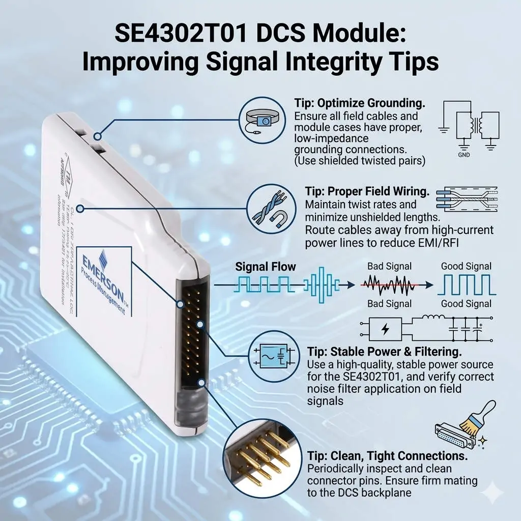
SE4302T01 DCS Module Improving Signal Integrity Tips

SE4302T01 DCS Module: Improving Signal Integrity Tips

Resolving Channel Interference in SE4302T01 DCS Modules through Advanced Signal Isolation

Addressing Signal Integrity in High-Demand DCS Environments

The SE4302T01 module functions as a critical interface for signal acquisition within Distributed Control Systems (DCS). However, engineers frequently encounter channel interference in petrochemical and pharmaceutical plants. These facilities often feature long cable runs and significant electromagnetic interference (EMI). While some mistake these fluctuations for hardware failure, they usually stem from signal integrity issues. Maintaining measurement accuracy is vital to prevent false trips and ensure process stability across the plant.

SE4302T01 DCS Module Improving Signal Integrity Tips

SE4302T01 DCS Module Improving Signal Integrity Tips

The Importance of Galvanic Isolation for SE4302T01 Stability

Direct exposure to field signals without proper galvanic isolation makes the SE4302T01 vulnerable. Ground loops and common-mode noise can easily penetrate the system near high-power motors or Variable Frequency Drives (VFDs). Therefore, adding an external isolator provides a necessary barrier against electrical noise. This setup significantly improves signal stability and reduces intermittent faults that plague unprotected modules. According to recent industrial automation trends, robust isolation remains a top priority for preventing unexpected downtime.

Balancing Module Response Time and High-Frequency Noise Filtering

Fast-response modules provide excellent dynamic tracking but also capture unwanted transient noise. Many engineers observe that “interference” is actually high-frequency noise misinterpreted as valid data. To solve this, you must balance responsiveness with stability. Introducing an isolator with built-in hardware filtering allows the DCS to receive clean data. Moreover, configuring software damping within the control system further refines the signal. This dual-layered approach ensures the system reacts to real process changes rather than electrical artifacts.

Compliance with EMC Standards and Environmental Immunity

Industrial sites rarely provide ideal conditions for electromagnetic compatibility (EMC). Modules operating near their immunity limits, as defined by IEC 61000 standards, often exhibit erratic behavior. This instability frequently occurs in aging plants where shielding and grounding systems have degraded over time. Isolation devices act as an additional EMC barrier. As a result, they extend the reliability of the SE4302T01 even in harsh, noisy environments where standard hardware might struggle to maintain precision.

Operational Guidance for Maintenance and Installation

Before replacing hardware, maintenance teams should verify the grounding topology of the entire loop. Improper grounding, such as multiple ground points or floating shields, causes most interference cases.

  • ✅ Ensure signal cable shields connect to ground at only one end to prevent loops.
  • ✅ Install signal isolators close to the DCS input side in mixed-signal environments.
  • ✅ Combine isolators with Surge Protection Devices (SPD) for outdoor or long-distance cable runs.
  • ✅ Periodically inspect cable integrity to identify degraded shielding or insulation.

These proactive steps often resolve “faults” without necessitating expensive module replacements.

Strategic Insights from Powergear X Automation Limited

At Powergear X Automation Limited, we emphasize that channel interference is often a system-level challenge. Replacing the SE4302T01 should be your final step after exhausting wiring and isolation checks. We have observed that adding high-quality isolators is more cost-effective than constant hardware swaps. This strategy improves long-term stability without altering the fundamental DCS architecture. Investing in proper isolation today prevents the high costs associated with process instability and false alarms tomorrow.

Industrial Application Scenarios

  • Petrochemical Refining: Prevents signal drift in temperature and pressure loops near heavy rotating machinery.
  • Pharmaceutical Manufacturing: Ensures precise measurement during sensitive batch processes where EMI from cleanroom equipment is high.
  • Retrofit Projects: Provides a practical solution for noise issues when rerouting existing cables is physically impossible.

Frequently Asked Questions (FAQ)

Q: How can I distinguish between a hardware failure and external interference?
Disconnect the field wiring and apply a local, clean 4-20mA source directly to the module input. If the reading stabilizes instantly, the issue lies in the field wiring or EMI, not the internal hardware of the module.

Q: Will adding an isolator introduce a delay in my control loop?
Most modern signal isolators have a response time in the millisecond range. While they do add a negligible delay, the benefits of a stable, noise-free signal far outweigh the slight increase in latency for 95% of industrial applications.

Q: Is it necessary to use HART-compatible isolators with the SE4302T01?
If your field instruments rely on HART protocol for remote calibration or diagnostics, you must select an isolator that supports HART pass-through. Standard isolators will strip the digital signal, leaving only the analog 4-20mA component.

For high-performance components and expert support in optimizing your DCS, please visit the official Powergear X Automation Limited website to view our latest technical solutions.

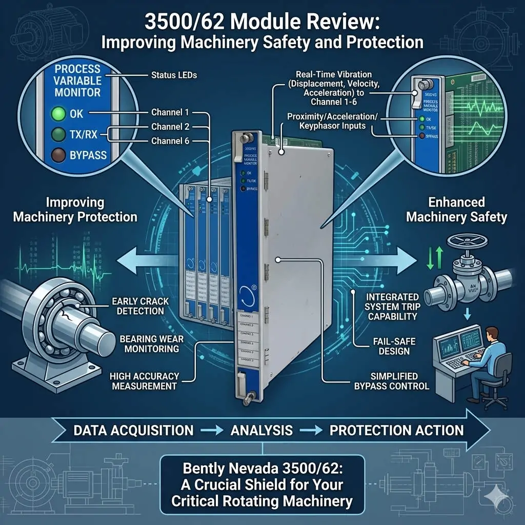
3500-62 Module Review Improving Machinery Safety and Protection

3500/62 Module Review: Improving Machinery Safety and Protection

Enhancing Machinery Protection with the Bently Nevada 3500/62 Process Variable Monitor

Bridging the Gap Between Process Data and Mechanical Integrity

The Bently Nevada 3500/62 serves as a vital bridge in modern industrial automation. While standard vibration monitors track mechanical movement, this module integrates critical process variables like pressure and temperature. In heavy industries, mechanical failures often stem from process upsets. Therefore, correlating these data points within a single rack is essential for comprehensive asset protection. By using the 3500/62, operators gain a holistic view of machine health, moving beyond simple vibration analysis to true condition-based monitoring.

3500-62 Module Review Improving Machinery Safety and Protection

3500-62 Module Review Improving Machinery Safety and Protection

Technical Core: Standardizing 4–20 mA Analog Input Integration

The 3500/62 module primarily utilizes 4–20 mA analog inputs to interface with field transmitters. This compatibility ensures a seamless connection with standard flow, pressure, and temperature sensors used in factory automation. Because it accepts direct signals, the system eliminates the need for external converters. Consequently, this architecture reduces signal drift and minimizes points of failure. However, engineers must carefully calculate the loop power budget. High-load smart transmitters may occasionally require an external power source to maintain signal integrity during peak operation.

Advanced Alarm Logic and System Redundancy

Integrated alarm setpoints differentiate the 3500/62 from basic PLC or DCS modules. This hardware allows for “unified trip logic” directly within the protection rack. For example, a system can trigger a shutdown only when both high vibration and extreme bearing temperature occur simultaneously. This local logic execution provides faster response times than cross-platform communication via Modbus. Moreover, it creates a redundant layer of safety. Even if the primary control system fails, the 3500/62 ensures the machinery remains within safe operating limits.

Optimizing Installation for High-Noise Industrial Environments

Signal interference remains a significant challenge in plants featuring large Variable Frequency Drives (VFDs). Analog signals are sensitive to electromagnetic noise, which can cause “phantom” alarms. At Powergear X Automation Limited, we recommend using shielded twisted-pair cabling grounded at only one end. Furthermore, installers should never run low-voltage signal wires parallel to high-voltage power lines. In extreme cases, adding signal isolators can prevent ground loops that compromise measurement accuracy. Proper cable management significantly improves the Mean Time Between Failures (MTBF) for the entire monitoring system.

Strategic Procurement: Compatibility and Selection Criteria

Choosing the right module requires a thorough understanding of the existing 3500 rack ecosystem. The 3500/62 is generally backward compatible with older racks, but firmware versioning is critical. Before purchasing, verify that your Rack Configuration Software supports the specific revision of the module. Additionally, check the power supply capacity of the rack. Adding multiple process variable monitors can increase the thermal load and current draw. Ignoring these hardware constraints often leads to unexpected commissioning delays or analog signal instability.

Professional Insight from Powergear X Automation Limited

From the perspective of Powergear X Automation Limited, the 3500/62 is a diagnostic powerhouse rather than just an input card. As the industry moves toward “Industry 4.0,” the demand for synchronized data increases. While a DCS handles broad process control, the 3500 system provides the “high-speed” protection layer. We suggest that users do not view this as a replacement for a PLC. Instead, treat it as a specialized tool for critical rotating equipment where the cost of a missed trip far outweighs the module investment.

Industrial Solution Scenarios

  • Centrifugal Compressor Protection: Monitoring suction pressure and discharge temperature alongside vibration to prevent surge conditions.
  • Steam Turbine Management: Integrating casing expansion and steam pressure into the 3500 rack for real-time thermal stress analysis.
  • Remote Pump Stations: Using the 3500/62 to provide autonomous protection in areas with limited DCS connectivity.

Technical Implementation Checklist

  • ✅ Verify transmitter loop power requirements (Active vs. Passive loops).
  • ✅ Match the 3500/62 firmware with the Rack Interface Module (RIM) version.
  • ✅ Implement proper shielding and separation from high-voltage AC cables.
  • ✅ Configure “Danger” and “Alert” setpoints based on machinery manufacturer specifications.

Frequently Asked Questions (FAQ)

Q: Does the 3500/62 support HART protocol for smart transmitter diagnostics?
While the 3500/62 reads the 4–20 mA analog signal, it typically does not pass HART digital diagnostic data to the rack. If you need HART information for asset management, you should use a signal splitter to send the data to a specialized HART multiplexer or DCS.

Q: Can I use this module for high-speed turbine overspeed protection?
No. The 3500/62 is designed for static or slowly changing process variables. For overspeed protection, you must use the dedicated 3500/53 Electronic Overspeed Detection System, which has the necessary millisecond response time.

Q: How does the 3500/62 handle a “Transmitter Not OK” status?
The module monitors the input current. If the signal drops below a certain threshold (typically <2 mA), the system flags a “Not OK” status. This prevents a broken wire from accidentally triggering a machinery trip, improving overall system reliability.

For more technical specifications and high-quality parts, please visit the Powergear X Automation Limited website for expert support.

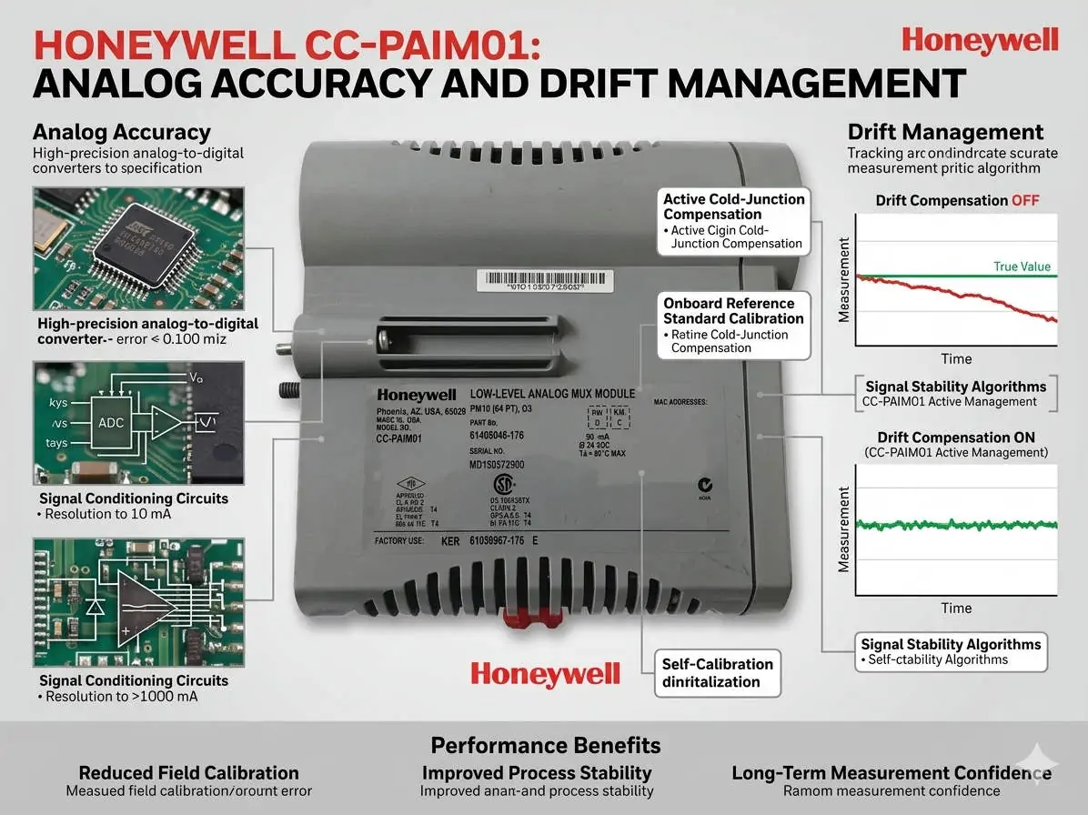
Honeywell CC-PAIM01 Analog Accuracy and Drift Management

Honeywell CC-PAIM01: Analog Accuracy and Drift Management

Maximizing Precision: The Role of Temperature Compensation in CC-PAIM01 Modules

The Critical Value of Thermal Stability in Analog Inputs

The Honeywell CC-PAIM01 analog input module plays a vital role in maintaining high-accuracy signal acquisition. In volatile industries like petrochemicals and pharmaceuticals, thermal drift can compromise process stability. Even minor temperature fluctuations can lead to measurement bias. Therefore, engineers must prioritize internal temperature compensation to ensure product quality. Accurate field calibration maintains signal integrity and prevents the need for premature hardware replacement.

Honeywell CC-PAIM01 Analog Accuracy and Drift Management

Honeywell CC-PAIM01 Analog Accuracy and Drift Management

Understanding the Impact of Temperature Drift Coefficients

While the CC-PAIM01 includes built-in compensation, environmental stress and component aging eventually introduce drift. A typical drift coefficient of ±0.01%/°C might appear insignificant at first glance. However, in high-precision flow or pressure loops, these errors accumulate quickly. As a result, uncompensated drift creates offset errors in 4–20 mA signals. This issue is particularly prevalent in outdoor cabinets that lack strict climate control.

Maintaining High-Resolution Signal Fidelity

Thermal stability directly influences the effectiveness of high-resolution A/D conversion. When temperatures shift, the resulting offset errors reduce the module’s effective resolution. This loss of fidelity can trigger unnecessary control loop oscillations in complex DCS environments. Moreover, advanced control strategies like tight-tolerance PID loops become less reliable. Consistent thermal management ensures that the module provides the granular data required for modern factory automation.

Professional Field Calibration Procedures

Successful calibration requires a stable environment and precise tools. Our team at Powergear X Automation recommends following these technical steps:

  • Isolate the input channel from the process.
  • Connect a precision signal source with ±0.005% accuracy.
  • Allow the module to thermally stabilize for 45 minutes.
  • Execute zero and span calibration via DCS engineering tools.
  • Apply multi-point checks at 4, 12, and 20 mA.

Strategic Cabinet Thermal Management

Hardware placement significantly affects long-term performance. Always install modules away from heat-generating components like power supplies or VFDs. Ideally, maintain cabinet temperature variations within a ±5°C range. In one refinery project, relocating a module 15 cm away from a heat source reduced alarms by 60%. Therefore, physical layout is just as important as software configuration for system reliability.

Expert Insights from Powergear X Automation

At Powergear X Automation, we believe technical discipline drives operational excellence. Many engineers misdiagnose grounding noise as temperature drift. Always verify your single-point grounding and use shielded twisted-pair cables before recalibrating. By combining proper installation with routine verification, you extend the lifecycle of your Honeywell assets while ensuring peak performance.

Technical Summary Checklist

  • ✅ Verify temperature compensation curves during commissioning.
  • ✅ Use precision calibrators for all analog loop checks.
  • ✅ Maintain strict physical separation from power cables.
  • ✅ Implement annual calibration for critical control loops.
  • ✅ Ensure firmware compatibility before replacing legacy modules.

Industrial Application Scenarios

  • Pharmaceutical Batch Processing: Maintaining strict temperature-dependent chemical reactions.
  • Oil and Gas Custody Transfer: Ensuring highly accurate flow measurements for billing.
  • Power Generation: Monitoring turbine pressure sensors in high-heat environments.

Implementation FAQ

Q1: When should I prioritize recalibration over module replacement?
If you notice a consistent offset that correlates with seasonal temperature changes, recalibration is the first step. Modules usually last over a decade, but their compensation curves may shift after 3 to 5 years of continuous operation.

Q2: How does the CC-PAIM01 handle extreme outdoor environments?
While rated for -20°C to +60°C, the module performs best when shielded from direct sunlight. We recommend using air-conditioned panels or sun shields to keep the internal cabinet temperature stable near 25°C.

Q3: What is the biggest mistake made during field calibration?
Skipping the thermal “warm-up” period is a common error. If you calibrate a cold module immediately after opening the cabinet, the settings will drift again as the module reaches its operating temperature.

For more technical guides and high-quality automation hardware, visit the Powergear X Automation website.

Back to Top
Product has been added to your cart