Fix 10ms Output Drop in 140DDO35300 Quantum Hot Standby PLC
Engineering Guide: Resolving 10ms Output Drops in Schneider 140DDO35300 Quantum Hot Standby Systems
In high-availability factory automation, achieving true seamless failover remains a critical challenge for process engineers. Schneider Electric Quantum Hot Standby systems deliver reliable CPU redundancy. However, field teams often notice a brief 10-millisecond physical output drop on the 140DDO35300 digital output module during primary-to-standby switchover. Powergear X Automation presents this technical evaluation to clarify that this drop stems from physical hardware control transfers rather than PLC program logic loss. Merely modifying PLC code will not eliminate this interruption.
Core Engineering Value of True Output Retention
In continuous manufacturing industries like chemical processing and power generation, redundant DCS and PLC control systems must protect field actuators. When a primary CPU fails, connected solenoids, relays, and contactors must maintain their physical state. Even a 10-millisecond voltage drop can trip sensitive interposing relays or trigger emergency valve shutdowns. Engineers must distinguish between CPU memory synchronization and physical output hardware behavior. Schneider Electric documentation highlights that CPU failover does not guarantee zero-millisecond interruption at every discrete output channel.
Technical Specifications of the 140DDO35300 Solid-State Module
The 140DDO35300 is a 32-point, 24 VDC solid-state positive logic output module designed for high-density discrete switching. Unlike mechanical relays, solid-state output transistors respond instantly to control bus transitions. If the primary CPU surrenders control, the output channel enters a brief holding window before the standby CPU re-drives the hardware bus. Consequently, even when the software logic state remains true, the physical terminal voltage drops to zero temporarily.
Diagnosing Signal Drops with Oscilloscope Verification
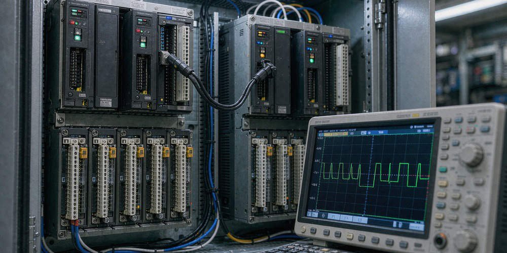
Relying solely on HMI graphical displays or PLC status bits creates dangerous false assumptions during commissioning. HMI screens display internal memory states rather than terminal voltages. Field engineers should capture the failover transition using a digital oscilloscope. Connect channels to monitor the 140DDO35300 output terminal, the load coil voltage, the 24 VDC power bus, and the CPU Hot Standby status signal. Oscilloscope traces clearly expose physical power interruptions that standard software diagnostics miss.
Aligning CPU Failover Times with Physical Output Performance
Quantum Hot Standby architectures isolate CPU redundancy from field I/O execution. Reducing the PLC scan time in Schneider Control Expert or Unity Pro will not prevent physical hardware power dips. System integrators must evaluate the entire signal chain, including application data sync, remote I/O (RIO) drop convergence, and load drop-out times. Therefore, true bumpless operation requires hardware-level mitigation rather than software adjustments.
Field Mitigation 1: Installing DC Hold-Up Modules and Buffer Circuits
Installing a 24 VDC hold-up module or capacitive buffer supply represents the most practical field solution. Placing a DC buffer module between the 140DDO35300 output and sensitive load coils maintains terminal voltage during the 10-millisecond failover gap. When selecting a buffer device, calculate the load current, minimum drop-out voltage, and coil discharge time to ensure sufficient hold-up margin.
Field Mitigation 2: Implementing Redundant Output Wiring Schemes
Critical interlocks demand redundant physical wiring paths rather than single-channel drivers. Never connect solid-state transistor outputs directly in parallel, as reverse current can damage the module channels. Instead, drive dual interposing relays connected in a parallel contact arrangement. This configuration ensures that if one channel drops out for 10 milliseconds, the parallel relay contact maintains current to the critical actuator.
Field Mitigation 3: Verifying External 24 VDC Power Supply Voltage
Transient dips on the primary 24 VDC power bus often mimic Hot Standby failover faults. Heavy contactor inrush currents or inadequate power supply capacity can cause transient voltage sags. Engineers must verify that the 24 VDC power distribution bus remains stable during switchover. Resolving power distribution bottlenecks eliminates artificial voltage drops on output channels.
Field Mitigation 4: Evaluating Mechanical Load Drop-Out Time Constants
Every mechanical relay or solenoid valve exhibits a specific drop-out time constant. If a contactor features a 30-millisecond mechanical release delay, a 10-millisecond voltage interruption will not cause physical contact opening. Conversely, fast-acting electronic relays with sub-5ms response times will trip immediately. Engineers must compare actual load specifications against measured output drop durations before redesigning control panels.
Procurement Guide and Upgrade Considerations for Legacy Hardware
Schneider Electric has placed the Modicon Quantum 140DDO35300 into mature lifecycle status, recommending modern Modicon X80 series modules like the BMXDDO3202K as migration paths. However, procurement teams must realize that replacing a 140DDO35300 with an X80 module will not automatically eliminate failover dips without evaluating the underlying RIO topology. Plant managers must plan comprehensive hardware migrations that account for backplane compatibility, field wiring adapters, and system architecture.
Practical Application Scenario: Petrochemical Valve Control System
A petrochemical refinery experienced sudden emergency valve closures during routine Quantum Hot Standby CPU switchover tests. The system utilized 140DDO35300 modules to drive 24 VDC pilot solenoid valves. High-speed recording revealed a 12-millisecond output drop during CPU failover, causing the fast-acting pilot valves to release.
The engineering team implemented a two-part solution. First, they installed compact 24 VDC buffer modules across the critical output loops to ride through voltage dips up to 50 milliseconds. Second, they integrated interposing isolation relays wired in redundant parallel configurations. During subsequent switchover testing, the solenoid coils experienced continuous power, fully eliminating process trips without altering the validated PLC safety logic.
For expert component sourcing, lifecycle management, and hardware solutions for industrial systems, visit Powergear X Automation to support your plant operations.
Frequently Asked Questions (FAQ)
Q1: Can I fix the 140DDO35300 10ms output drop by editing the PLC program logic?
No. The brief output drop occurs at the physical hardware interface during primary-to-standby bus control transfer. Software logic retainment cannot override physical output channel re-initialization.
Q2: Does the X80 BMXDDO3202K module solve the Hot Standby drop issue automatically?
Not necessarily. While the BMXDDO3202K is the recommended modern replacement, physical output behavior during failover depends on the overall RIO architecture, Ethernet drop adaptation, and power distribution design.
Q3: How do I measure the exact drop-out duration on a digital output module?
Connect a digital storage oscilloscope directly across the 140DDO35300 output terminal and 0V common. Trigger the scope on the falling edge of the 24 VDC signal while initiating a manual CPU switchover.