Understanding Broken Wire Detection Logic
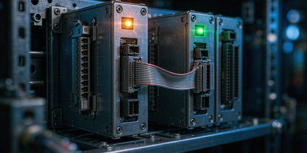
The Schneider Electric 140AVI03000 analog input module serves as a cornerstone for signal acquisition in high-stakes industrial automation. This Modicon Quantum component reliably captures low-level signals like 4–20 mA from various field instruments. In my experience at Powergear X Automation, we often see engineers treat “Broken Wire” alarms as simple hardware glitches. However, this diagnostic feature is a critical safety tool that prevents process deviations in oil, gas, and pharmaceutical sectors.
The 140AVI03000 utilizes advanced loop supervision to monitor input current levels continuously. When the current falls below a specific threshold, typically 3.5 mA, the module triggers a fault. This mechanism ensures the PLC does not mistake a failed sensor for a valid low process reading. Consequently, operators can trust that their flow or pressure data reflects actual field conditions.

Enhancing System Stability Through Input Isolation
Electrical noise from Variable Frequency Drives (VFDs) or large motors often plagues industrial environments. The 140AVI03000 offers robust channel-to-bus isolation to combat these interference issues. This isolation prevents ground loops and induced noise from causing momentary current drops. Without this protection, control systems frequently suffer from “ghost” alarms that disrupt production cycles.
Avoiding Common Wiring Topology Errors
Compatibility with both 2-wire and 4-wire transmitters makes this module versatile for factory automation. Nevertheless, technicians often confuse the power sourcing requirements during the commissioning phase. The 140AVI03000 does not always provide loop power for every configuration. Misunderstanding this distinction remains a leading cause of immediate Broken Wire faults upon system startup.
Proven Field Strategies for Maintenance and Reliability
Statistical data suggests that over 60% of analog signal failures stem from external wiring rather than internal module defects. Before replacing expensive hardware, follow these field-tested steps:
Measure the loop current using a high-precision multimeter.
Verify the external 24 VDC supply for all 4-wire transmitters.
Confirm that the wiring polarity matches the official Schneider diagrams.
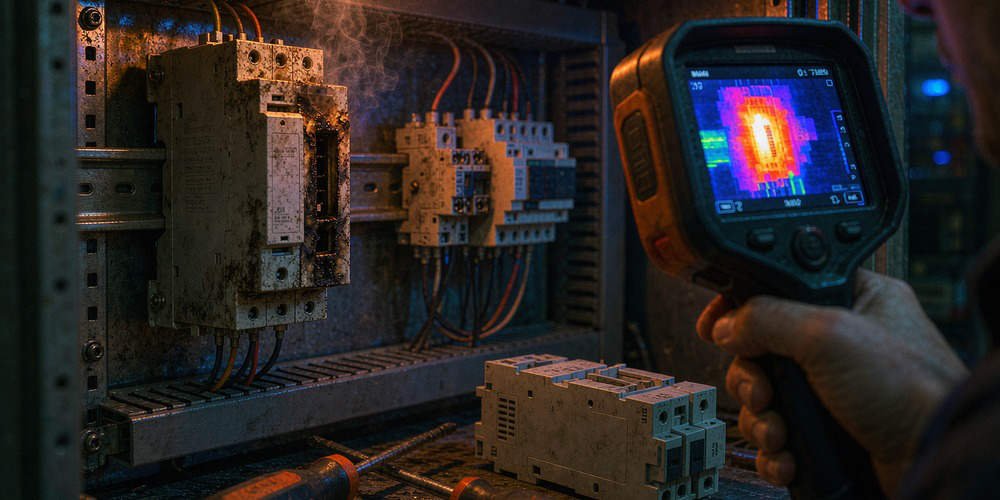
Check terminal tightness, especially in high-vibration areas like pump skids.
Install ferrules on all analog signal wires to ensure permanent contact.
Optimizing Shielding and Grounding Standards
Improper grounding often creates intermittent faults that are difficult to diagnose. Experts follow IEC 61158 standards by grounding the cable shield at only one end. Usually, the control cabinet serves as the best single-point ground location. Floating shields or multiple ground points create circulating currents, which mimic the symptoms of a physical break in the wire.
Author Insights: The Future of Analog Diagnostics
At Powergear X Automation, we believe that proactive diagnostics like those in the 140AVI03000 are non-negotiable for modern DCS and PLC architectures. While digital protocols like HART or Foundation Fieldbus are growing, the 4–20 mA standard remains the industry’s backbone. Investing in modules with “Broken Wire” detection ensures your facility meets the traceability requirements of highly regulated industries.
Application Scenarios
- Chemical Processing: Monitoring hazardous pressure levels where signal loss could lead to tank overpressure.
- Water Treatment: Ensuring continuous flow data for chemical dosing pumps to maintain water quality.
- Oil & Gas Skids: Providing reliable feedback in high-vibration environments near large compression units.
Technical Best Practices Checklist
- ✅ Use shielded twisted-pair cables for all low-level analog signals.
- ✅ Separate signal cables from high-voltage power lines by at least 30cm.
- ✅ Implement software filtering to ignore sub-millisecond signal transients.
- ✅ Document all loop resistance values during the initial commissioning phase.
- ✅ Test the module annually using a calibrated 4-20 mA loop simulator.
Frequently Asked Questions (FAQ)
Q1: How can I distinguish between a sensor failure and a module channel failure?
The most effective method is the “Channel Swap” test. Move the suspected field wire to a known working channel on the module. If the error moves with the wire, the issue lies in the field. If the error stays on the original channel, the 140AVI03000 hardware may require repair.
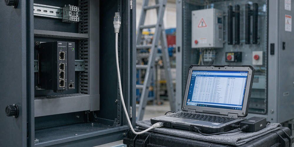
Q2: Does this module require specific configuration in EcoStruxure Control Expert?
Yes, you must enable the “Broken Wire” detection feature within the hardware configuration shortcut. If you use a 0–20 mA scale instead of 4–20 mA, you should disable this feature. A 0 mA signal is “normal” for 0-20 mA loops, which would trigger false alarms.
Q3: Can I use the 140AVI03000 for high-accuracy temperature measurements?
While this module handles 4-20 mA signals from temperature transmitters, it is not a direct RTD or Thermocouple module. For maximum accuracy, ensure your transmitter is calibrated. The module’s 12-bit to 16-bit resolution (depending on settings) is generally sufficient for most industrial thermal processes.
For more technical guides, high-quality PLC components, and expert automation support, visit Powergear X Automation. We help you optimize your control systems for maximum uptime.