How to Resolve “Main Controller Communication Timeout” on the ABB PCD235A101
In high-power industrial applications, communication latency or unexpected dropouts can stall entire production lines. The ABB PCD235A101 3BHE032025R0101 interface board serves as a vital data link. It connects main controllers to medium-voltage drive units and upper-level DCS architectures. However, engineers frequently encounter a critical fault: a “Main Controller Communication Timeout” paired with an inactive Ethernet LINK LED. Resolving this issue requires structured physical-layer diagnostics and hardware validation.
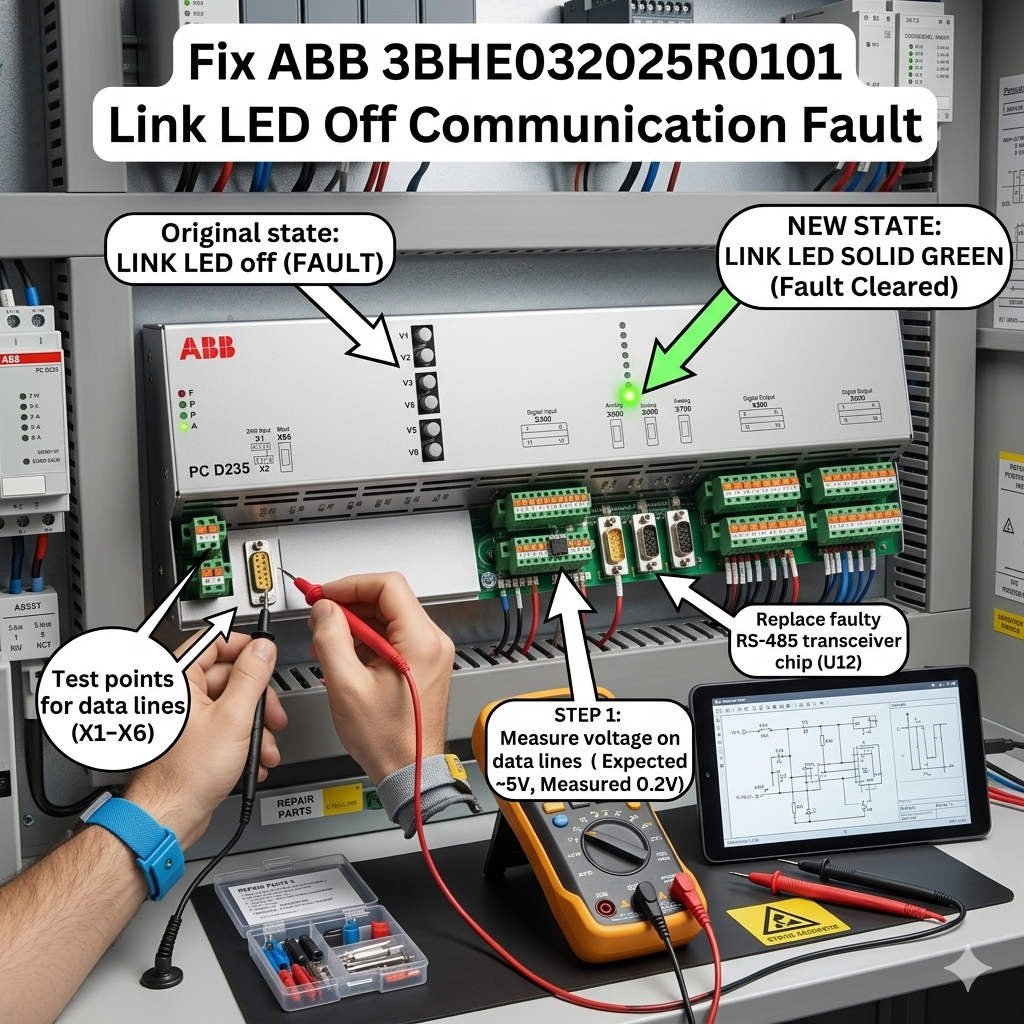
Fix ABB 3BHE032025R0101 Link LED Off Communication Fault
The Functional Role of PCD235A101 in Industrial Automation
The PCD235A101 manages high-speed synchronous data streams within complex drive control topologies. In sectors like petrochemical processing and mining, this board handles real-time variable processing. Consequently, any interruption can trigger safety interlocks or trip critical compressor trains. The card relies on robust physical transceiver logic to convert signals accurately. It ensures that the drive control unit communicates seamlessly with broader factory automation networks.
Physical Layer Diagnostics for Inactive LINK Indicators
The Ethernet LINK LED on this board operates directly via hardware transceiver circuits. Therefore, a dark LINK lamp indicates that physical carrier synchronization has completely failed. Firmware modifications or soft reboots will rarely correct this underlying condition. In real-world applications, up to 70% of these faults stem from physical damage. Cracked RJ45 solder tracks caused by heavy cabinet vibration often break the circuit. Additionally, micro-corrosion on backplane gold pins can block connection signals entirely.
Analyzing Backplane Voltage Stability and Power Quality
Stable DC power distribution is essential for proper communication initialization during system boot-up cycles. The PCD235A101 requires an ultra-clean 5VDC logic rail from the main rack. Standard multimeters only capture static values, which often mask high-frequency voltage ripple. Excessive ripple can cause the onboard Ethernet PHY chip to freeze during initialization. For facilities handling conductive dust, accumulated particulate matter can gradually increase backplane impedance. This deterioration eventually creates unpredictable communication dropouts.
Network Compatibility Across Mixed Control Systems
Legacy drive hardware often encounters negotiation conflicts when connected to modern network equipment. The PCD235A101 may fail to establish a link with modern high-speed switches. Forcing a 1000 Mbps connection or activating Energy Efficient Ethernet (EEE) protocols typically disrupts auto-negotiation. As a result, the port shuts down due to timing discrepancies. Engineers should implement managed industrial switches and lock connection speeds to 100 Mbps Full Duplex. This approach guarantees rigid timing loops for the control strategy.
Selection Criteria and Retrofit Distinctions
When selecting a replacement interface card, buyers must evaluate version compatibility matrices. Newer revisions of the PCD235A101 3BHE032025R0101 feature updated transceiver components. These components might require matching drive control firmware updates to work correctly. Installing an unverified hardware combination can introduce intermittent timeout errors. Therefore, technical teams should audit their current rack generation before ordering components. Keeping an exact firmware-matched spare card in inventory significantly reduces Mean Time to Repair (MTTR).
Step-by-Step Maintenance and Optimization Procedures
- ✅ Physical Inspection: Replace standard network patches with shielded CAT6 industrial cables.
- ⚙️ Contact Restoral: Clean the backplane edge connector using an approved electronics solvent.
- 🔧 Power Verification: Check the 5VDC logic rail using an oscilloscope under full operational load.
Perspective from Powergear X Automation Limited
At Powergear X Automation Limited, we note that network infrastructure issues cause many board failures. High-voltage drive cabinets produce severe electromagnetic fields that damage unshielded components. We recommend installing dedicated line filters for auxiliary power units. For brownfield retrofits, verifying hardware revisions ensures seamless deployment. To browse our verified stock of ABB components and access advanced technical specifications, visit https://www.powergearx.com/ today.
Real-World Application Scenarios
- Steel Rolling Mills: Minimizing severe mechanical shock effects on RJ45 connectors via vibration-damping mounting.
- Pumping Stations: Eliminating auto-negotiation lockups by bypassing unmanaged commercial switches inside the cabinet.
- Refinery Compressors: Restoring critical link metrics during thermal expansion cycles by replacing oxidized backplane carriers.
Frequently Asked Questions (FAQ)
1. What should I test first when the LINK LED remains completely dark?
Bypass the onsite network switches and connect your engineering laptop directly to the board using a verified cable. If the indicator stays dark, inspect the onboard RJ45 port pins for mechanical damage.
2. Can a firmware conflict cause the physical network indicators to turn off?
No, the initialization indicators depend purely on hardware connections. If the light remains off, the problem lies within the physical layer, power circuits, or the internal bus routing.
3. When is it better to replace the board rather than trying to clean it?
We recommend replacing the card immediately if you find bulging capacitors or discoloration on multi-layer traces. Corroded traces can cause intermittent open circuits that are impossible to fix reliably in the field.