Emerson SS4303T01 Online Replacement Guide | DeltaV Maintenance
Is Online Replacement of the Emerson SS4303T01 Safe for Active Control Systems?
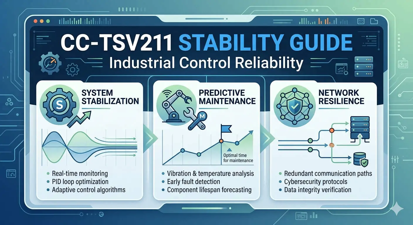
Industrial automation relies on continuous uptime. In modern DCS environments, the ability to maintain hardware without halting production is a critical operational requirement. The Emerson SS4303T01 module is a central component in DeltaV architectures. While engineers often discuss its “hot-swap” capabilities, successful online replacement requires a deep understanding of system redundancy and environmental risks. This article explores the technical nuances of servicing this hardware in live environments.

Emerson SS4303T01 Online Replacement Guide DeltaV Maintenance
Understanding the Functional Role of the SS4303T01 in DCS
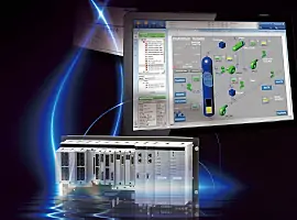
The SS4303T01 serves as a vital communication or power interface within the Emerson DeltaV ecosystem. It facilitates data flow between the controller and I/O subsystems. In high-stakes industries like oil and gas or pharmaceuticals, this module ensures that process variables reach the control logic without latency. Its design prioritizes high availability. However, the hardware works within a complex backplane. Therefore, its performance depends on the integrity of the entire carrier assembly.
The Mechanics of Redundancy and Hot-Swapping Logic
True hot-swapping is only possible when the system maintains a redundant state. Before you remove an active SS4303T01, you must verify that the secondary communication path is fully synchronized. If the redundant partner is offline or degraded, pulling the module will trigger a system trip. Active diagnostics tools in the DeltaV explorer provide real-time health checks. We recommend confirming “Good” status across all communication nodes. Moreover, you should check for “Standby Ready” indicators to ensure a seamless transition during the physical swap.
Evaluating Physical Risks During Online Maintenance
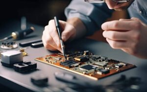
Physical factors often cause more failures than software logic. In older plants, the carrier connectors may suffer from oxidation or mechanical fatigue. Inserting a new module into a worn backplane can create intermittent “ghost” faults. These faults are difficult to troubleshoot because they appear randomly under different thermal loads. Additionally, electrostatic discharge (ESD) remains a silent killer of industrial electronics. Always use grounded wrist straps. As a result, you protect the sensitive CMOS components inside the replacement unit from latent damage.
Strategic Considerations
When sourcing specialized hardware like the SS4303T01, reliability is the primary keyword for procurement officers. Market data indicates that nearly 40% of unplanned downtime in factory automation stems from improper maintenance of aged components. Adhering to ISA environmental standards ensures your hardware lasts its full lifecycle. Furthermore, engineers should prioritize original equipment to avoid firmware mismatches. For high-quality components and expert technical support, professionals often turn to trusted distributors like Powergear X Automation Limited.
Operational Guidelines for Field Engineers
- ✅ Pre-Maintenance Audit: Verify the redundancy synchronization status in the DeltaV Diagnostics shell.
- ⚙️ Environmental Check: Ensure the cabinet temperature is within limits to prevent thermal shock to the new module.
- 🔧 Mechanical Precision: Align the module carefully with the carrier guides to avoid bending backplane pins.
- 📊 Post-Installation Monitoring: Observe the LED indicators and system logs for at least 15 minutes after the swap.
Expert Insight from Powergear X Automation Limited
At Powergear X Automation Limited, we have observed that many “module failures” are actually infrastructure issues. We suggest that maintenance teams inspect cabinet grounding every six months. Poor grounding creates electrical noise that mimics hardware faults. If you are looking to optimize your spare parts inventory or need guidance on legacy system compatibility, explore our comprehensive catalog at https://www.powergearx.com/ for reliable automation solutions.
Application Scenario: Refinery Distillation Column
In a refinery setting, a distillation column must run for years without interruption. If a communication module fails, the SS4303T01 allows the maintenance team to restore redundancy while the column remains in a steady state. By following a strict MOC (Management of Change) protocol, the team replaces the faulty unit during a scheduled “low-activity” shift. This strategy eliminates the risk of a $500,000 production loss associated with an emergency shutdown.
Frequently Asked Questions (FAQ)
Q1: Can I replace the module if the “Active” light is blinking?
A: A blinking light usually indicates a synchronization process or a diagnostic warning. You should never pull the module until the redundancy status is confirmed as “Stable” and “Standby” in the software.
Q2: Does the new module require a firmware download after insertion?
A: In most DeltaV versions, the controller automatically detects the hardware revision. However, if the version mismatch is significant, you may need to perform a “Partial Download” to align the firmware.
Q3: What is the biggest cause of failure after an online swap?
A: Most post-replacement failures are due to improper seating in the carrier or latent ESD damage. Ensure the module is firmly locked and that you are using proper anti-static procedures.