Diagnosing a Dead ABB PC D232 3BHE022293R0101: How to Verify Backplane Power Supply
In heavy industrial automation, a sudden hardware failure can stall an entire production line. The ABB PC D232 (part number 3BHE022293R0101) processor interface board is a critical component in excitation control and DCS environments. However, engineers often face a frustrating scenario: the board shows no LED indicators after power-on. Fortunately, this symptom does not always mean the board is dead. It frequently points to a failure in the backplane power distribution network instead.

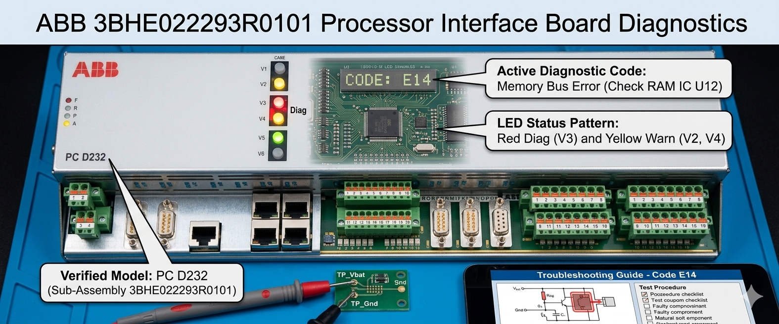
ABB 3BHE022293R0101 Processor Interface Board Diagnostics
The Critical Role of the 3BHE022293R0101 Interface Board
The PC D232 serves as the primary communication link between high-level controllers and field equipment. It manages boot-up sequencing and synchronizes rapid data transfers within the cabinet. In sectors like power generation and petrochemical processing, this module ensures absolute operational stability. Because it handles vital processor interface tasks, any degradation in power will cause a complete communication freeze. As a result, maintaining a steady voltage supply is essential for total system availability.
Analyzing the Technical Principles of the 5V Logic Supply
The 5V DC rail provides the essential logic power for core microprocessors, FPGAs, and communication chips. For optimal performance, this rail must remain within a strict tolerance of 4.75V to 5.25V. If the voltage drops below this range, the CPU cannot execute its boot sequence. Consequently, the board will show no LED activity whatsoever. In older cabinets, power supply unit (PSU) capacitor degradation is the leading cause of excessive voltage ripple. High ambient temperatures accelerate this aging process, creating intermittent startup faults under full load slots.
Understanding 24V Distribution and Safety Interlock Chains
While the 5V rail powers internal logic, the 24V DC rail controls interface relays and permissive enable circuits. Industrial control systems usually expect a 24V supply to stay within 21.6V and 26.4V. In turbine excitation applications, the system routes this voltage through physical safety chains. If a cabinet door switch or safety relay opens, the board loses power completely. Therefore, engineers must trace the entire safety interlock before condemning the microprocessor card. A loose terminal fuse can easily mimic a total hardware failure.
Mechanical Reliability of Backplane DIN Connectors
Mechanical wear remains a hidden source of electronic component failure in factory automation. The PC D232 relies on high pin-density DIN connectors to connect with the backplane. In high-humidity or coastal chemical environments, these pins are highly vulnerable to oxidation. This chemical film increases contact resistance, blocking low-voltage power from entering the PCB. Often, simply re-seating the card restores operation temporarily. This behavior confirms a mechanical connectivity issue rather than a genuine component failure inside the board circuitry.
Step-by-Step Power Verification for Field Engineers
- ✅ Verify Cabinet Input: Confirm that the main AC power feeding the redundant PSU modules is completely normal.
- ⚙️ Measure the 24V Rail: Use a digital multimeter across the 0V COM and the fuse holder output terminal.
- 🔧 Test the 5V Logic: Check test points while the module is seated to measure actual slot load conditions.
Strategic Selection and Backward Compatibility Rules
When procuring a replacement module, buyers must remember that physical appearance can be highly deceiving. Different revisions of the PC D232 might look identical but carry completely different firmware packages. Mixing incompatible board revisions can lock up the system bus upon power-on. Moreover, older backplanes might not support the advanced diagnostic features of newer card iterations. Therefore, always match the model with your original Bill of Materials (BOM) and check active system lifecycles.
Expert Advisory from Powergear X Automation Limited
At Powergear X Automation Limited, our field experience shows that nearly 40% of returned processor boards are fully functional. In reality, bad grounding bars and weak power supplies cause the majority of field diagnostic alarms. We strongly recommend that site teams implement a formal lock-out tag-out (LOTO) procedure before testing. Furthermore, avoid hot-swapping these modules unless your specific cabinet manual explicitly permits it. To source certified, reliable parts and upgrade legacy components, visit our store at https://www.powergearx.com/.
Real-World Application and Scenario Planning
In a large hydroelectric power plant, an excitation cabinet failure can halt electricity generation instantly. During a recent maintenance outage, a technician found a PC D232 board with no active status lights. Instead of executing an emergency replacement, the engineer systematically checked the backplane test nodes. The multimeter revealed a 5V logic rail reading of only 4.2V. The team replaced the aging DIN-rail PSU, instantly restoring the system without touching the expensive processor board hardware.
Frequently Asked Questions (FAQ)
1. Why shouldn’t I measure the 5V logic rail with the processor board pulled out?
Many industrial backplanes use switching regulators that require a minimum circuit load to function correctly. Measuring an empty slot can give false voltage readings that disappear once you insert the heavy board.
2. Can external voltage surges cause the board’s LEDs to turn off permanently?
Yes. High-current motor starters and VFD switching can send transient voltage spikes through unprotected lines. These spikes fry the internal DC/DC converter on the board, disabling all diagnostic LEDs.
3. What safe cleaner should we use if we discover oxidized backplane contacts?
Always use a fast-evaporating, manufacturer-approved electronic contact cleaner. Ensure the cabinet is completely de-energized before spraying, and allow the pins to dry fully before re-inserting the interface board.