
Over 50,000 hot-selling automation module components.

How to Adjust Bently Nevada 3300 XL Probe Gap Voltage to -10V

How to Accurately Adjust Bently Nevada 3300 XL 8mm Probe Gap Voltage to -10VDC Without Removing the Bearing Cap

In industrial automation and field machinery maintenance, calibrating proximity probes on critical rotating equipment remains a vital task. Machinery like steam turbines, centrifugal compressors, and heavy-duty pumps rely on the Bently Nevada 3500 Monitoring System for continuous vibration protection. Field technicians frequently encounter sealed bearing housings that prevent direct mechanical measurements between the probe tip and the target shaft. Therefore, engineers must adjust the probe position electrically by measuring the output voltage using a digital multimeter. Powergear X Automation provides this practical engineering guide to help maintenance teams set the target gap voltage precisely to -10VDC.

Understanding the Fundamental Purpose of Eddy Current Probes

The 3300 XL 8mm eddy current proximity transducer system converts physical shaft displacement into proportional DC voltage signals. According to industry statistics from machinery health reports, over 70 percent of rotating equipment trip failures stem from improper sensor calibration or loose mounting hardware. As a result, maintaining an accurate gap voltage ensures that your factory automation monitoring system detects abnormal shaft position changes before catastrophic damage occurs. Proper setup protects high-value assets and prevents expensive unplanned downtime across processing facilities.

Analyzing Key Technical Specifications and the -10VDC Work Point

The standard operating point for a Bently Nevada 3300 XL 8mm transducer system sits at -10VDC, which corresponds to the midpoint of its linear range. The system provides a standard scale factor of 7.87 V/mm (200 mV/mil) across a 2.0 mm (80 mil) linear operating window. When the probe tip moves closer to the conductive shaft, the negative output voltage increases towards -18VDC or further. Conversely, moving the probe away from the target shaft causes the output reading to drift towards 0VDC. Maintaining this precise midpoint ensures maximum dynamic measurement range for both axial position and radial vibration monitoring.

Ensuring Component Matching Across Probe Systems

A complete proximity transducer system requires three matched components: the 3300 XL probe, an extension cable, and a Proximitor Sensor. Mixing components with different electrical system lengths degrades measurement accuracy significantly. For instance, connecting a 5-meter Proximitor to an 8-meter combined probe and cable assembly skews the scale factor. Moreover, unmatched components cause signal drift, erratic vibration readings, or channel status errors inside the control systems. Maintenance personnel must verify that the total electrical length matches the Proximitor label specification before performing voltage adjustments.

Accounting for Thermal Shaft Expansion During Cold Setup

Setting the gap voltage to -10VDC on cold machinery does not guarantee that the voltage remains unchanged during full operation. Thermal growth causes the rotor shaft to expand axially and radially relative to the stationary bearing pedestal. Consequently, the operating gap voltage often shifts by 1VDC to 3VDC as the turbine or compressor reaches thermal equilibrium. Experienced engineers at Powergear X Automation recommend logging the cold installation gap voltage and reviewing the trend data immediately after machine startup to establish an accurate operating baseline.

Step-by-Step Multimeter Calibration Procedure

  1. Identify the Proximitor Terminals: Locate the 3300 XL Proximitor Sensor terminals inside the local junction box. Connect the black negative multimeter lead to the COM terminal and the red positive lead to the OUT terminal. Select the DC voltage scale on your meter.
  2. Read Current Gap Voltage: Measure the static DC voltage while the machine remains completely shut down. A reading of -6.5VDC indicates the probe sits too far from the shaft, whereas a reading of -13.5VDC indicates the probe sits too close.
  3. Adjust Physical Position: Loosen the locking nut and rotate the threaded probe body carefully. Threading the probe clockwise moves it closer to the shaft, increasing the negative voltage. Threading it counterclockwise moves it away, bringing the voltage closer to 0VDC.
  4. Lock and Verify Final Reading: Adjust the position in small increments until the multimeter displays -10.0VDC (+/- 0.5VDC). Hold the probe body stationary while tightening the jam nut to prevent unintended rotation during final locking.

Troubleshooting Common Field Installation Issues

When multimeter readings fluctuate wildly during adjustment, check the extension cable coaxial connectors first. Loose or contaminated connectors introduce high contact resistance and intermittent noise. Furthermore, ensure that the cable shield grounds at a single point according to OEM specifications to prevent ground loops. If the gap voltage refuses to move beyond -2VDC to -4VDC, verify that the probe tip faces a flat conductive steel surface rather than a keyway, shoulder fillet, or non-magnetic material.

B2B Buyer Guide for System Compatibility

Procurement teams must exercise caution when replacing legacy 3300 series components with newer 3300 XL 8mm hardware. While 3300 XL probes feature superior physical durability and chemical resistance, they require matching 3300 XL Proximitor Sensors to operate within specification. Never attempt to connect a 3300 XL probe to an older 7200 series Proximitor Sensor. Additionally, buyers should always specify the exact thread type, unthreaded length, total case length, and armor options needed for specific machine housings.

Application Scenario: Refinement of Compressor Axial Displacement Sensors

During a overhaul at a petrochemical plant, maintenance contractors installed two new axial displacement probes into a high-pressure gas compressor. The bearing cap remained sealed, making mechanical feeler gauge measurements impossible. The field team connected high-precision multimeters across the Proximitor OUT and COM terminals. They rotated each probe body until the voltage stabilized at -10.2VDC and locked the mounting hardware securely. This electrical adjustment allowed the DCS and 3500 rack to initialize without channel faults, enabling a smooth machinery startup sequence.

For genuine Bently Nevada components, replacement modules, and expert technical advice regarding your plant monitoring systems, visit Powergear X Automation to explore our extensive inventory of industrial controls.

Frequently Asked Questions (FAQ)

Q1: What happens if I leave the gap voltage set to -14VDC instead of -10VDC?
Leaving the probe set at -14VDC positions the sensor near the edge of its linear region. Thermal expansion during machine operation can push the probe out of its linear range entirely, causing false alarms or loss of vibration data.

Q2: Can I adjust the gap voltage while the machine is running?
No. Adjusting proximity probe gap voltage while the shaft rotates poses severe safety risks to both personnel and equipment. You must perform all physical probe adjustments while the machine remains safely shut down.

Q3: Why does my 3500 Monitor display a “Not OK” status after setting the probe to -10VDC?
A “Not OK” status usually indicates an open circuit, incorrect wiring polarity, or an invalid channel configuration inside the 3500 Rack Configuration Software. Verify your terminal connections and ensure the software configuration matches the installed sensor model.


Bently Nevada 3500-42M Gap Voltage Cable Length Impact Guide_

Bently Nevada 3500/42M Gap Voltage & Cable Length Impact Guide

Impact of Probe Cable Length Errors on Gap Voltage in Bently Nevada 3500/42M Systems

In modern industrial automation, machinery protection systems safeguard critical rotating equipment across heavy processing industries. Vibration monitoring systems rely heavily on precise eddy current proximity transducers to track shaft movement. The Bently Nevada 3500/42M Proximity Monitor requires strict length matching between the proximity probe, extension cable, and Proximitor sensor. Mismatches directly shift the DC bias gap voltage and undermine overall measurement accuracy. Powergear X Automation presents this technical guide to help field engineers prevent diagnostic errors and optimize control systems performance.

Bently Nevada 3500-42M Gap Voltage Cable Length Impact Guide_

Bently Nevada 3500-42M Gap Voltage Cable Length Impact Guide_

Understanding Proximity Transducer System Architecture

Eddy current transducer systems function as calibrated, high-frequency tuned resonant circuits rather than simple electrical wiring. Standard installations utilize either a 5-meter or 9-meter overall system length. A 5-meter system typically combines a 1-meter probe with a 4-meter extension cable. Conversely, a 9-meter system pairs a 1-meter probe with an 8-meter extension cable. The Proximitor sensor contains internal oscillator components configured specifically for these fixed cable lengths. Therefore, mixing mismatched components alters the electrical impedance and distorts the output curve.

How Cable Length Mismatches Shift Gap Voltage Output

The 3500/42M monitor module reads raw voltage signals directly from the Proximitor sensor. However, using incorrect cable lengths fundamentally skews the sensor’s voltage-to-distance conversion ratio. A standard target gap setting generates approximately -10V DC across a 2mm linear operating range. Misconfiguring a 9-meter physical system as a 5-meter setup in the rack software alters this output baseline. As a result, actual gap voltage might drift toward -7V DC or -13V DC, shifting the measurement out of the calibrated linear window.

Consequences of Linear Range Offsets on Machinery Protection

Operating outside the calibrated linear zone creates severe operational risks for turbomachinery. If the gap voltage remains within the margin, the monitor OK LED stays green and vibration values update. However, the available linear headroom drops significantly, increasing the risk of signal saturation during high-vibration events. If the gap voltage strays beyond linear limits, the channel triggers false alarms or records misleadingly low vibration amplitudes. Consequently, plant operators might miss critical shaft movement during heavy equipment startup cycles.

API 670 Standard Compliance for Factory Automation

Machinery protection in continuous processing plants must strictly adhere to the API 670 standard. According to industry reports, improper sensor calibration accounts for over 15% of false machinery shutdown trips globally. API 670 explicitly mandates that proximity probes, extension cables, and Proximitors remain fully matched and factory-calibrated. Engineers must never interchange 5-meter and 9-meter system components arbitrarily during emergency maintenance. Procurement teams must verify complete system part numbers before issuing replacement purchase orders.

Step-by-Step Field Commissioning and Verification Sequence

  1. Inspect Physical Hardware: Check the part numbers on the proximity probe, extension cable, and Proximitor sensor to confirm total physical system length.
  2. Verify Software Configuration: Connect to the 3500 Rack Configuration Software and verify that the selected transducer type matches the installed physical hardware length.
  3. Measure Physical Mechanical Gap: Set the probe mechanical clearance using feeler gauges or a dial indicator to the specified target distance.
  4. Confirm Measured DC Voltage: Read the channel gap voltage on the module front panel or software interface to ensure it registers near -10V DC.

Field Installation Practices and Cable Routing

Proper physical installation prevents signal degradation in noisy factory automation environments. Extension cables routed near turbomachinery experience high mechanical vibration and electromagnetic interference. Engineers should maintain minimum cable bend radii specified by the manufacturer and avoid sharp 90-degree turns. Furthermore, field technicians must secure extension cables in rigid metallic conduits and ground the shielding strictly according to facility EMC guidelines. Unsecured cables vibrate freely, inducing false high-frequency noise spikes on the PLC registers.

B2B Procurement and Hardware Replacement Guidelines

Replacing legacy Bently Nevada hardware requires a thorough review of existing control panel documentation. Maintenance teams often assume that probes with identical mounting threads are universally interchangeable. However, swapping a 5-meter probe into a 9-meter Proximitor circuit ruins system calibration. When sourcing replacement parts for factory automation infrastructure, procurement managers must evaluate CPU firmware, rack backplane compatibility, and system length parameters. Verifying these configurations offline prevents extended plant downtime during scheduled turnarounds.

Application Scenario: Gas Turbine Shaft Vibration Troubleshooting

During a planned overhaul of a power generation plant, technicians replaced a damaged 3300 XL proximity probe on a gas turbine shaft. Shortly after startup, the 3500/42M monitor generated a persistent gap voltage alarm on Channel 2, reading -5.2V DC instead of the nominal -10V DC target, although the shaft mechanical clearance measured correctly.

The engineering team investigated the installation and discovered that a 9-meter replacement probe assembly had been connected to an existing 5-meter Proximitor sensor. To rectify the issue, the team replaced the Proximitor with a verified 9-meter model and updated the 3500 Rack Configuration software settings accordingly. The gap voltage immediately stabilized at -9.8V DC, restoring full linear measurement range and bringing the machinery protection system back into full API 670 compliance.

For reliable hardware sourcing and expert technical support on Bently Nevada monitoring components, visit Powergear X Automation to find high-performance solutions for your plant control systems.

Frequently Asked Questions (FAQ)

Q1: Can I adjust the 3500/42M software settings to correct a physical cable length mismatch?
No. Changing software parameters cannot compensate for physical impedance errors in the Proximitor circuit. You must match the physical probe, cable, and Proximitor length before updating the software configuration.

Q2: How does incorrect gap voltage affect overall vibration reading accuracy?
An incorrect gap voltage pushes the probe operation toward the non-linear edges of its calibration curve. This causes the system to either attenuate or exaggerate actual vibration amplitudes during operation.

Q3: What is the primary operational difference between a 5-meter and a 9-meter proximity system?
The primary difference lies in the internal electrical tuning of the Proximitor sensor. The 9-meter Proximitor accounts for additional electrical resistance and capacitance inherent in the longer extension cable.

Bently Nevada 3500-42M Bypass LED Issue Proximitor Wiring Guide_

Bently Nevada 3500/42M Bypass LED Issue: Proximitor Wiring Guide

Why Reverse Proximitor Wiring Illuminates the Bypass LED on Bently Nevada 3500/42M Modules

Precision machinery protection requires dependable sensors and advanced control systems in industrial automation. The Bently Nevada 3500/42M Proximity/Seismic Monitor module measures shaft vibration and displacement on critical turbomachinery. However, reversing polarity on eddy current Proximitor sensors creates unexpected behavior. The module activates the Bypass LED while the Alert LED remains dark. At Powergear X Automation, our technical team analyzes why polarity errors disrupt monitoring channels and explains how field engineers can resolve this issue efficiently.

Bently Nevada 3500-42M Bypass LED Issue Proximitor Wiring Guide_

Bently Nevada 3500-42M Bypass LED Issue Proximitor Wiring Guide_

The Core Role of Eddy Current Sensors in Machinery Protection

Rotating machinery in power generation and chemical plants relies on eddy current probes for real-time condition monitoring. The Proximitor sensor drives high-frequency radio signals through the probe tip to form an electromagnetic field. As the metal shaft moves, eddy current losses change the probe impedance. The Proximitor converts this impedance shift into a proportional DC voltage. The 3500/42M module processes this analog voltage to calculate shaft vibration amplitudes. Proper sensor operation allows plant operators to detect bearing wear and rotor unbalance before catastrophic failures happen.

Understanding the Impact of Reversed -24VDC Supply Polarity

Bently Nevada 3300 XL and 3500 proximity probe systems require a stable -24VDC power supply. Reversing terminal connections halts the internal active electronics within the Proximitor. Consequently, the sensor fails to produce a valid dynamic signal or a stable DC gap voltage. The output voltage floats near zero or clamps to an invalid rail level. B2B engineers must realize that the 3500/42M module cannot calculate real vibration data without a proper gap voltage. Therefore, the monitor inhibits alarm processing to prevent false plant trips.

Analyzing 3500/42M Bypass State Logic and Safety Design

The 3500/42M monitor features sophisticated onboard diagnostics rather than simple signal threshold detection. When an invalid input voltage occurs, internal logic marks the channel as Not OK. The monitor then suppresses alarm outputs and illuminates the Bypass LED. Field personnel often misinterpret this Bypass light as a software override. However, the system automatically enters this protective state when sensor signals fall outside valid operating ranges. This safety design ensures that unpowered or incorrectly wired sensors do not trigger accidental machine shutdowns.

Complete Diagnostic Checklist for Bently Nevada Channel Alerts

Illuminating the Alert LED on a 3500/42M module requires satisfying five distinct monitoring conditions in sequence:

  • Correct Power Supply: The Proximitor must receive a steady -24VDC supply with correct polarity.
  • Valid Gap Voltage: The probe must operate within its linear range, typically producing -8VDC to -10VDC at nominal gap.
  • Healthy Channel Status: The 3500/42M module must register a Channel OK condition in internal memory.
  • Active Alarm Logic: Software configuration must enable channel alerts without manual user bypass.
  • Vibration Threshold Exceeded: Shaft vibration amplitude must exceed the programmed alert setpoint value.

Step-by-Step Commissioning and Troubleshooting Sequence

Engineers should follow a structured sequence when troubleshooting a Channel Not OK or active Bypass status:

  1. Verify Terminal Wire Definitions: Confirm connections at Terminal A (-24VDC), Terminal B (COM), and Terminal C (Signal OUT) instead of relying solely on wire colors.
  2. Measure Static Gap Voltage: Use a digital multimeter to measure DC voltage across COM and OUT terminals at the field junction box.
  3. Inspect System Event Logs: Connect via 3500 Rack Configuration Software to check for specific fault messages like Input Voltage Fault.
  4. Clear Software Bypass Overrides: Ensure maintenance teams clear all manual software bypass flags after completing field wiring corrections.

Field Installation Best Practices and Cable Shielding Rules

High-vibration machinery environments present severe electromagnetic noise from variable frequency drives and high-power motors. Signal cables must utilize twisted-pair construction with overall shielding. Engineers must connect the cable shield to ground at the control cabinet end only. Dual-ended shield grounding creates circulating earth loops, which introduce artificial electrical noise onto the -24VDC supply lines. Proper wiring practices protect delicate proximity signals and prevent false vibration alarms across factory automation networks.

B2B Procurement and Hardware Replacement Guidelines

Replacing legacy Bently Nevada Proximitors requires verifying technical specifications rather than assuming direct hardware equivalence. Procurement specialists must match probe diameters, system lengths, and scale factors. For example, mixing 5mm probes with 8mm Proximitor drivers shifts the output scale factor from 7.87 mV/um to incorrect levels. Modern 3300 XL components maintain backward compatibility with older 3500 racks, but engineers must verify system calibration in the 3500 software prior to commissioning.

Application Scenario: Gas Turbine Vibration Monitoring Circuit

During a scheduled overhaul on a 50MW gas turbine, technicians installed new 3300 XL 8mm proximity probes on the main bearing housings. Upon powering up the control cabinet, the 3500/42M module displayed solid Bypass LEDs on channels 1 and 2, while the Alert LEDs remained completely unlit. The maintenance team initially suspected damaged 3500/42M input cards.

However, field diagnostic checks revealed that contractors had transposed the -24VDC power supply and Signal OUT conductors at the intermediate junction box. Restoring proper terminal polarity allowed the Proximitors to establish a stable -9.2VDC gap voltage. The 3500/42M module automatically cleared the Channel Not OK state, extinguished the Bypass LED, and activated normal machinery protection without requiring hardware replacement.

For genuine machinery protection hardware and technical support on Bently Nevada components, visit Powergear X Automation to source certified control system modules for your facility.

Frequently Asked Questions (FAQ)

Q1: Does reversing -24VDC polarity permanently damage a Bently Nevada Proximitor?
Usually no. Bently Nevada Proximitors include reverse-polarity protection diodes designed to withstand short-term wiring errors. However, prolonged exposure to incorrect voltages or excessive power supply currents can cause internal component degradation.

Q2: Why does the 3500/42M module show a Bypass LED instead of a red Fault LED?
The Bypass LED indicates that the monitor is inhibiting its relay and alarm outputs for that channel. An invalid signal from a reversed Proximitor causes the system to automatically enter bypass mode to prevent false plant trips.

Q3: Do I need to recalibrate the 3500/42M rack after replacing a Proximitor sensor?
If you replace the sensor with an identical part number and matching cable length, full recalibration is not required. However, you must verify the DC gap voltage in the 3500 Rack Configuration Software to confirm correct mechanical installation.

Bently Nevada 3300 XL Proximitor Power Wiring Hazards

Will a +24VDC Misconnection Burn Your Bently Nevada 3300 XL 8mm Proximitor?

In heavy industrial environments, machinery protection systems serve as the ultimate defense line for multi-million dollar rotating assets. The Baker Hughes Bently Nevada 3300 XL 8mm Proximitor Sensor plays a vital role in these systems. This sensor monitors critical parameters like shaft vibration and thrust position on steam turbines, centrifugal compressors, and large pumps. However, this specialized sensor utilizes a negative -24VDC power supply. This negative voltage architecture differs completely from the standard positive +24VDC supply found in most factory automation setups. Consequently, field technicians frequently ask: What happens if we accidentally connect a positive +24VDC line to this negative-powered sensor?

At Powergear X Automation, we analyze this common wiring hazard from a practical field engineering perspective. If you are looking to purchase or upgrade your industrial control system components safely, please explore our comprehensive product catalog at Powergear X Automation.

The Risk of Thermal Damage in Reversed Polarity Scenarios

Yes, connecting a +24VDC supply directly to a Bently Nevada 3300 XL 8mm Proximitor Sensor carries a extremely high risk of permanent component damage. The internal circuitry of the Proximitor uses a negative voltage design where the positive terminal functions as the system common ground (COM). If you apply a positive +24VDC potential to the -24VDC supply terminal, you reverse the polarity across the entire internal circuit board.

Many standard industrial sensors feature robust reverse-polarity protection diodes. However, Bently Nevada proximitors prioritize high-frequency response and analog signal precision over general-purpose protection. Consequently, keeping a reversed positive voltage connected for more than a few seconds will cause overheating, eventually burning out sensitive internal components like input-stage transistors or op-amps.

Understanding the Negative -24VDC Legacy in Vibration Monitoring

To understand this unique design, we must look back at the history of industrial control systems and electronic instrumentation. Early operational amplifiers and high-speed analog circuits achieved superior stability and lower noise floors using negative voltage rails. Because eddy current sensors detect sub-micron shaft movements, minimizing signal noise is absolutely paramount.

By standardizing on a -24VDC rail, Bently Nevada isolates fragile dynamic signals from the common electrical noise generated by positive-rail factory automation equipment. Therefore, this negative supply arrangement ensures that high-frequency shaft vibrations are transmitted cleanly over long distances to the Bently Nevada 3500 rack without signal degradation.

Analyzing Signal Precision and Critical Protection Actions

The 3300 XL 8mm Proximitor outputs a continuous analog voltage proportional to the distance between the probe tip and the target shaft. Usually, this output scale operates at 7.87 V/mm (200 mV/mil). If the power supply experiences instabilities or wiring faults, the output voltage might drift.

In turbomachinery monitoring, a drifting signal can cause catastrophic consequences. For instance, a false high vibration reading might trigger an emergency trip, costing a petrochemical plant hundreds of thousands of dollars in lost production. Conversely, if the signal fails entirely due to a burned-out sensor, the system cannot detect an actual shaft rub, risking severe mechanical failure. Thus, securing a clean and stable -24VDC source is crucial for plant safety.

How Environmental Stresses Compound Electrical Faults

Proximitor sensors rarely operate in clean, climate-controlled environments. Instead, they sit in local enclosures mounted directly on hot turbine decks, exposed to high ambient temperatures, relentless mechanical vibrations, and oily atmospheres. Over time, constant thermal expansion and physical vibrations can loosen terminal screws, crack wire insulation, or damage shielding cables.

When wiring becomes loose, intermittent short circuits or ground loops can occur. If field technicians attempt troubleshooting without verifying power polarities on their multimeters, they can easily cross-wire the positive-rail PLC lines with the negative-rail sensor lines during a rushed turnaround.

Field Installation and Preventative Maintenance Procedures

To prevent costly damage to your vibration monitoring loops, we suggest implementing the following safety steps during commissioning and maintenance:

  • Verify Before Connecting: Always use a calibrated digital multimeter to measure the potential between the terminal wires before connecting them to the Proximitor. Ensure the supply line reads -24VDC relative to the COM terminal.
  • Use Dedicated Color Coding: Never assume standard wire colors like red represent positive lines. Implement distinct wire labels or jacket colors specifically for negative DC voltage distribution inside your junction boxes.
  • Implement Proper Isolation: If your facility only provides standard +24VDC power, install high-quality, DIN-rail mounted DC-to-DC converters to step down and invert the voltage safely.
  • Secure Shield Grounding: Connect the outer shield of the coaxial extension cable to the instrument ground at the monitor rack side only. This prevents ground loop currents from interfering with the analog signal.

Industrial Scenario: Resolving Power Discrepancies in Upgrades

Consider a chemical plant replacing its legacy distributed control systems (DCS). The new cabinet utilizes modern +24VDC power supplies for all field transmitters. To integrate the existing Bently Nevada 3300 XL loop, the engineering team cannot simply tap into the main +24VDC bus. Instead, they must install a dedicated isolated power converter module to generate the stable, clean -24VDC rail required by the proximitors. Taking this step ensures compatibility and protects the entire sensor chain from overvoltage failures.

Frequently Asked Questions (FAQs)

Q1: Can I use a standard 24V DC power supply by just swapping the positive and negative leads?
No. A standard power supply outputting +24VDC relative to ground cannot be simply reversed if its negative terminal is internally tied to the chassis or earth ground. Doing so will cause a direct short circuit. You must use a dedicated, isolated DC-to-DC converter designed to output a true negative voltage.

Q2: What are the immediate signs that a 3300 XL Proximitor has burned out?
A damaged proximitor typically stops modulating its output voltage entirely. The output voltage pin will either read 0V or peg to the limit (near the positive rail), and the Bently Nevada 3500 monitor will display a “NOT OK” status light accompanied by a channel bypass alarm.

Q3: Can 8mm and 11mm proximitor systems share the same power supply?
Yes, as long as both systems require -24VDC and the power supply can handle the total current draw. However, you must never mix the physical 8mm and 11mm probes or extension cables, as they have different electrical properties and calibration scales.

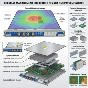
Thermal Management for Bently Nevada 3500-42M Monitors

Thermal Management for Bently Nevada 3500/42M Monitors

Thermal Management Risks for Bently Nevada 3500/42M Proximitor Seismic Monitors

Critical Role of Vibration Monitoring in Industrial Automation

The Bently Nevada 3500/42M serves as a vital component in high-reliability vibration and position monitoring. In sectors like oil and gas or power generation, this module protects critical rotating machinery. However, thermal stress can compromise its signal accuracy. Excessive heat directly undermines system stability. As a result, operators may face false alarms or missed mechanical faults.

Thermal Management for Bently Nevada 3500-42M Monitors

Thermal Management for Bently Nevada 3500-42M Monitors

Technical Impact of Overheating on Signal Integrity

The standard operating range for the 3500/42M typically spans from 0°C to 65°C. When internal temperatures exceed these limits, signal conditioning circuits begin to drift. Moreover, high heat accelerates the aging of electrolytic capacitors. This degradation shortens the module’s overall lifespan significantly. In many refinery environments, poor ventilation pushes temperatures above 70°C, causing intermittent channel dropouts.

Operational Risks and Response Stability Challenges

Heat introduces electrical noise and ADC instability within the monitor’s analog front-end. Consequently, proximitor signal scaling may drift away from calibrated values. These deviations often lead to false high-vibration alarms. Such errors trigger unnecessary machinery shutdowns and lost production time. Conversely, drift might mask early-stage bearing wear. This delay turns minor maintenance into a catastrophic unplanned outage.

System-Level Reliability in Rack Architectures

The 3500 system architecture relies on seamless integration between modules and power supplies. An overheating 3500/42M module increases the total thermal load of the entire rack. This heat transfer can trigger system-wide watchdog resets. Furthermore, redundant configurations suffer when thermal stress affects both primary and backup channels simultaneously. Maintaining a balanced thermal profile is essential for modern control systems.

Installation and Maintenance Best Practices

Field experience suggests that most overheating issues stem from installation errors rather than hardware defects. Engineers must prioritize cabinet thermal management to ensure longevity. Proper airflow prevents heat pockets from forming around sensitive electronics. In addition, dust accumulation acts as a thermal insulator, blocking essential cooling paths.

  • ✅ Maintain minimum airflow clearance at the top and bottom of the rack.
  • ✅ Avoid placing racks near heat sources like VFD panels or transformers.
  • ✅ Inspect and clean cabinet air filters monthly in dusty environments.
  • ✅ Utilize positive-pressure cabinets to keep internal components clean.
  • ✅ Verify total rack power load against the Power Supply Unit (PSU) rating.

Strategic Selection and Compatibility Insights

The 3500/42M offers backward compatibility within the 3500 rack series. However, hardware revisions and firmware versions must align for optimal performance. Older racks often lack the optimized airflow designs found in newer chassis. Therefore, users should verify rack revision levels before performing upgrades. Ignoring environmental conditions during selection often leads to premature module failure.

Expert Commentary from Powergear X Automation Limited

At Powergear X Automation Limited, we believe thermal management is a core part of machinery protection strategy. High-performance modules like the 3500/42M require stable environments to deliver precision. We often see random alarms disappear simply by redistributing modules to improve airflow. Treating cooling as an afterthought is a risk no plant manager should take. For high-quality automation parts and expert support, explore our solutions at Powergear X Automation Limited.

Application Scenarios and Solutions

  • High-Speed Turbines: Requires precise displacement monitoring where even 1°C of drift can trigger a safety trip.
  • Refinery Compressors: Utilizes seismic monitoring in harsh, ambient heat conditions requiring active cooling.
  • Remote Pumping Stations: Depends on self-diagnostics to alert maintenance teams of thermal rising before a fault occurs.

Frequently Asked Questions (FAQ)

Q: How can I detect overheating before it causes a system shutdown?
We recommend using thermal imaging cameras during routine inspections. This technique reveals hot spots that standard temperature sensors might miss. Also, monitor the “System Event List” for frequent self-test warnings or intermittent channel status changes.

Q: Will adding more fans to the cabinet always solve the problem?
Not necessarily. If the internal rack airflow is blocked by cabling or overpacking, external fans won’t help. You must ensure a clear path for air to move through the module slots themselves.

Q: Does the 3500/42M have a built-in automatic shutdown for heat?
The module includes self-protection logic, but it usually triggers a “Module Fault” rather than a clean shutdown. By the time this happens, your machinery protection is already compromised. Prevention through environmental control is the only safe approach.

Looking for reliable Bently Nevada modules or expert advice on rack configuration? Visit Powergear X Automation Limited today for global shipping and technical excellence.

Troubleshooting Bently Nevada 3300 NSv Metric Probe Issues

Resolving Zero Output: Troubleshooting Bently Nevada 3300 NSv Metric Probe Issues

Understanding the 3300 NSv Metric Probe

The Bently Nevada 3300 NSv Metric Probe is vital. It measures shaft vibration and position accurately. These proximity probes are essential for industrial automation systems. They monitor critical machinery health. The probe system relies on a non-contact technique. Therefore, zero output is a serious indicator of a fault. We must address this quickly to maintain machine protection.

Initial Diagnostics: Checking Power and Wiring

Start by verifying the system’s power supply. The 3300 NSv proximity system needs stable DC voltage. Check the wiring for physical damage first. Look for cuts, abrasions, or loose connections. Moreover, confirm correct polarity for the power leads. Incorrect wiring often causes a zero or unstable signal. Always consult the system’s manual for pinout specifications.

Troubleshooting Bently Nevada 3300 NSv Metric Probe Issues

Examining the Proximitor Sensor and Gap Voltage

The Proximitor Sensor is key to the system’s function. Measure the Gap Voltage at the Proximitor output terminals. A healthy system shows a specific DC voltage range. A zero reading here strongly suggests a probe or Proximitor failure. Alternatively, a short circuit in the probe cable could be the issue. Use a digital multimeter for accurate voltage measurement.

Investigating Probe and Cable Integrity

Probe damage is a common culprit. Inspect the probe tip for dirt, grease, or physical damage. Contaminants can block the electromagnetic field. The probe cable’s integrity is also crucial. Perform a resistance check on the cable and probe assembly. A high resistance reading indicates an open circuit. This issue directly leads to no output signal.

System Integration with PLC and DCS

The 3300 NSv output feeds into control systems like PLC or DCS. The zero output might originate downstream. Check the input module settings on your factory automation controller. Ensure the scaling and input type are correct for the 3300 NSv signal. Incorrect configuration prevents the controller from reading the signal. Therefore, verify software settings thoroughly.

Troubleshooting Bently Nevada 3300 NSv Metric Probe Issues

The Influence of Grounding and Shielding

Proper grounding is paramount in noisy industrial environments. Bad grounding causes signal interference or loss. Ensure the Proximitor housing is correctly grounded. Additionally, the cable shielding must be intact and correctly terminated. Good shielding prevents electrical noise from corrupting the low-level signal. This is a vital step in high-noise industrial automation.

Author’s Insight: Leveraging Modern Diagnostics

My experience suggests investing in modern diagnostic tools. Portable vibration analyzers can quickly test the probe’s health. Furthermore, trending the Gap Voltage is a powerful predictive tool. A gradual voltage shift precedes total signal loss. Bently Nevada continues to set the standard for machine protection. Proactive maintenance far outweighs reactive repairs.

Troubleshooting Bently Nevada 3300 NSv Metric Probe Issues

Application Scenario: Turbo-Machinery Monitoring

The 3300 NSv is frequently deployed on critical turbo-machinery. Imagine a compressor trip caused by a false zero-vibration reading. Downtime costs skyrocket rapidly. Regular checks of the system’s Gap Voltage prevent this scenario. A functioning proximity probe is the first line of defense in process control safety.

For reliable solutions and expert support in maintaining your industrial automation and control systems, and for high-quality replacement parts, Powergear X Automation Limited offers a wide range of products.

Click here to explore Powergear X Automation Limited‘s solutions for vibration monitoring and machine protection.

ModelTitleLink
1900/27-01Bently Nevada Vibration Monitor ModuleLearn More
60M100-00Bently Nevada Condition Monitoring SystemLearn More
3500/53 133388-01Bently Nevada Overspeed Detection ModuleLearn More
3500/45 176449-04Bently Nevada Position MonitorLearn More
3500/77M-03-00 176449-07Bently Nevada Recip Cylinder Pressure MonitorLearn More
Back to Top
Product has been added to your cart