
Over 50,000 hot-selling automation module components.
Measure Switching Noise on GE IS2020RKPSG3A Module

Measure Switching Noise on GE IS2020RKPSG3A Module

Analyzing High-Frequency Switching Noise on the GE IS2020RKPSG3A Power Supply Bus

In heavy industrial automation, clean low-voltage DC power safeguards processor integrity. The GE IS2020RKPSG3A power supply module delivers critical 5VDC power to EX2100 excitation systems and Mark VI control racks. However, a standard digital multimeter cannot capture high-frequency switching anomalies on the bus. This technical article covers the exact oscilloscope methods required to analyze dangerous ripple voltages. As a result, engineers can protect vital control networks from unexpected trips.

Measure Switching Noise on GE IS2020RKPSG3A Module

Measure Switching Noise on GE IS2020RKPSG3A Module

The Core Function and Architecture of the Power Module

The IS2020RKPSG3A utilizes a high-efficiency switch-mode power conversion architecture. It regulates voltage for downstream processing boards and critical communication interfaces. In addition, the internal circuitry isolates the control logic from heavy grid surges. This regulation keeps processing environments functional during severe load fluctuations. However, the native switching frequency inevitably introduces high-frequency ripple components onto the distribution lines.

Operational Principles of Oscilloscope Ripple Diagnostics

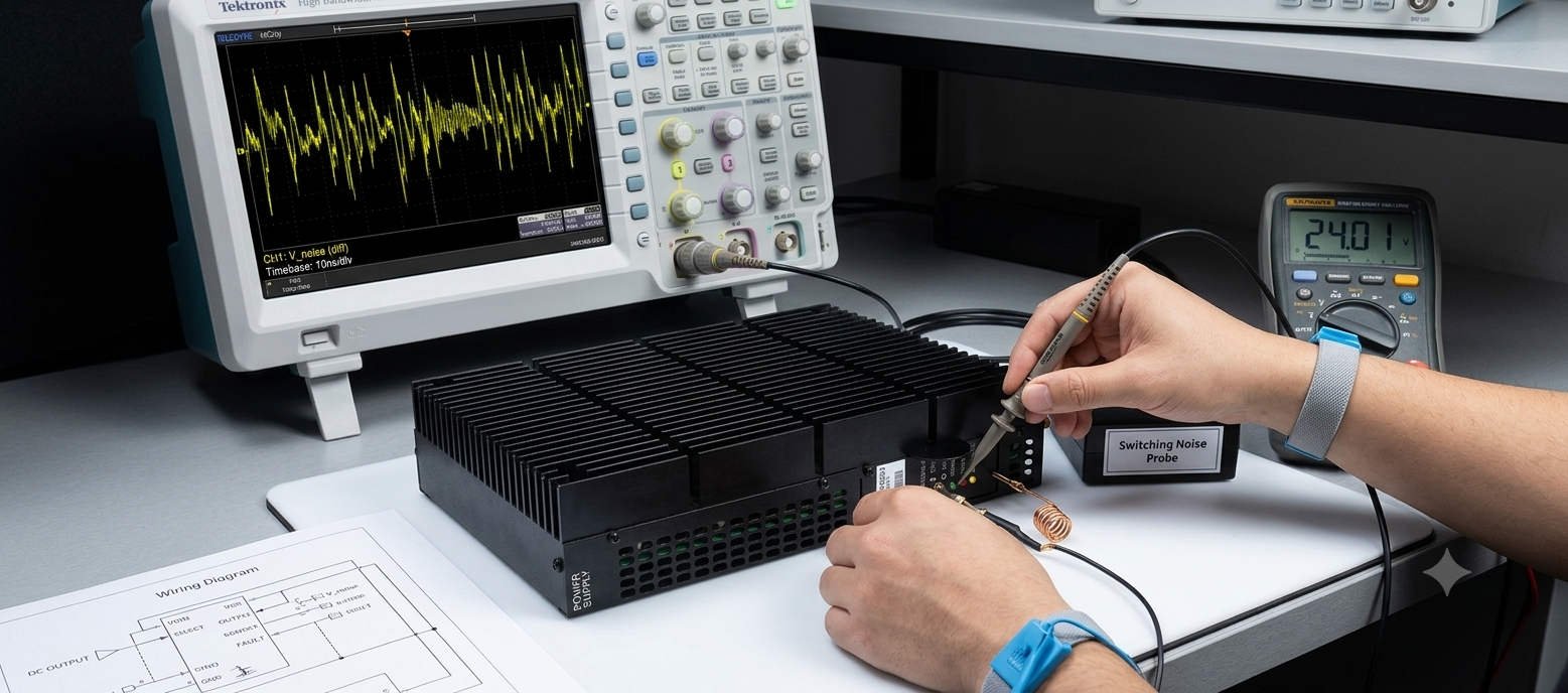
Detecting power anomalies requires proper instrument bandwidth selection and specific input coupling. Maintenance teams must utilize an oscilloscope with a minimum bandwidth of 100 MHz. Furthermore, engineers should select AC coupling to strip away the dominant 5VDC component. This setting allows the instrument to isolate the underlying millivolt-level noise. Consequently, you can observe high-frequency spikes that cause CPU watchdog resets and network dropouts.

The Critical Nature of Correct Probe Grounding

Standard oscilloscope probes often include long ground leads with alligator clips. However, these long wires act as antennas in noisy power generation environments. They capture stray electromagnetic interference from surrounding high-current bus ducts. To avoid false readings, technicians must utilize a short spring ground accessory. This practice restricts the ground loop area to under two centimeters. Therefore, it ensures that observed waveform ringing stems from the power supply rather than external induction.

Incorrect grounding methods can artificially inflate peak-to-peak voltage readings by several hundred percent. This inflation frequently leads to the premature replacement of perfectly healthy modules. Experienced engineers always measure ripple directly across the distribution terminal blocks. This strategic placement provides an accurate view of the voltage quality reaching the control systems.

Evaluating Compatibility and Module Selection Variations

When executing system updates, procurement officers must review original factory hardware revisions. The IS2020RKPSG3A features specific mechanical connector footprints and thermal properties. Older power supply variations may look identical but lack advanced internal noise filtering. In addition, backplane interface configurations can vary slightly across different controller generations. Relying on verified suppliers like Powergear X Automation Limited prevents costly installation compatibility errors.

Online Measurement and Calibration Benchmarks

  • Instrument Setup: Activate the 20 MHz bandwidth limiter to eliminate irrelevant high-frequency ambient radiation.
  • ⚙️ Baseline Profiling: Record bus waveforms during steady-state operation and major process load transitions.
  • 🔧 Network Inspection: Verify terminal torque values and check downstream filtering capacitors for leakage.

Expert Market Commentary from Powergear X Automation Limited

At Powergear X Automation Limited, we monitor component lifecycle patterns across major power plants globally. We notice that many power supply faults trace back to aging capacitors on adjacent I/O modules. As these capacitors degrade, they no longer buffer the 5VDC bus effectively. Therefore, we highly recommend performing preventative oscilloscope health checks annually. To find certified replacement components and optimize your factory automation assets, visit our portal at https://www.powergearx.com/.

Industrial Application Scenarios

In offshore gas extraction facilities, turbine control stability directly influences production metrics. The IS2020RKPSG3A maintains steady core voltages for the central processors. By implementing routine ripple tracking, maintenance crews can detect supply degradation months before a terminal blowout occurs. This proactive strategy ensures continuous operation of the DCS during severe ambient temperature changes.

Frequently Asked Questions (FAQ)

1. What peak-to-peak millivolt threshold indicates a need to replace the module?
While minor ripple is normal, high-frequency switching noise exceeding 50mVpp warrants close observation. If spikes regularly surpass 100mVpp during load transitions, replace the unit to protect downstream processors.

2. Can I replace the module while the turbine control system is active?
Live replacement depends on your rack redundancy configuration. In non-redundant simplex setups, pulling the module causes an immediate controller crash. Always confirm system redundancy status before attempting live servicing.

3. Why does the 5VDC bus show high noise when the power module passes bench tests?
This discrepancy usually indicates external electromagnetic interference. Poor cabinet bonding or missing cable shields allow noise from neighboring VFD equipment to induce voltage spikes onto the DC distribution lines.
Fix Ground Loop Alarms on GE IS200EPSM Excitation Modules

Fix Ground Loop Alarms on GE IS200EPSM Excitation Modules

How Ground Potential Differences Impact the Stability of the GE IS200EPSM Module

In high-power industrial automation, proper grounding topology is just as vital as input voltage quality. The GE IS200EPSM power supply module acts as a primary energy source within the EX2100 excitation platform. However, voltage potential differences between the DCS electronic ground and Protective Earth (PE) frequently degrade system stability. This technical review explores how ground loops introduce common-mode noise and compromise critical processor power networks.

Fix Ground Loop Alarms on GE IS200EPSM Excitation Modules

Fix Ground Loop Alarms on GE IS200EPSM Excitation Modules

The Architecture and Functional Value of the IS200EPSM

The IS200EPSM provides highly regulated low-voltage DC outputs directly to internal control electronics and sensitive I/O pathways. Its advanced power-conversion circuitry depends heavily on a clean, consistent reference potential to maintain tight regulation parameters. In continuous-process plants, this stability remains paramount for safeguarding against turbine trips and operational asset dropouts. Therefore, the module functions as the foundational electrical backbone for the wider system logic controller.

The Mechanics of Common-Mode Noise and Reference Drift

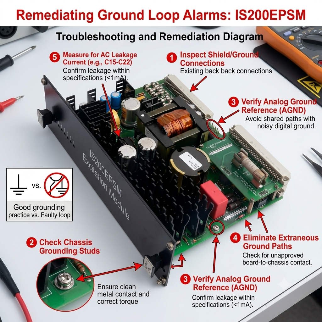
A significant voltage potential difference often arises when control cabinets lie far apart from primary substations. When the electronic ground shifts relative to PE, dangerous currents flow backward through data cable shields. Consequently, this circulating common-mode current generates electromagnetic interference that shifts the zero-volt baseline reference. As a result, processors misinterpret logic thresholds, triggering intermittent data packet losses, false high alarms, or random watchdog time-outs.

Field data indicates that grounding anomalies account for over 35% of unexplained controller resets in legacy systems. The internal filtering networks of the IS200EPSM can clamp minor transient currents effectively. However, continuous common-mode voltage stress above one volt exceeds the dampening limits of standard isolation transformers. This ongoing stress forces sensitive multi-layered boards to process high-frequency noise instead of clean power variables.

Surge Tolerance Limits and Semiconductor Degradation

Equipotential bonding directly influences how a power module handles lightning transients and massive motor switching events. If the control infrastructure lacks an integrated ground path, surge energy seeks alternative routes through internal semiconductor elements. This diverted energy creates severe thermal strain inside the module’s primary switching transistors and smoothing capacitors. Over time, this stress drastically reduces the mean time between failures (MTBF) for the power supply hardware.

Selecting and Validating the Correct Hardware Revision

When engineering system retrofits, maintenance teams must carefully match original bill-of-materials (BOM) part numbers. The IS200EPSM line incorporates distinct internal grounding configurations across different manufacturing series. Older system revisions may utilize isolated ground returns that conflict directly with modern, interconnected backplane frameworks. Procurement managers should cross-reference compatibility metrics through expert distributors like Powergear X Automation Limited to avoid startup logic faults.

Field Procedures for Grounding Diagnostics and Audits

  • Pre-Commissioning Test: Measure both AC and DC voltage between the electronic ground busbar and the cabinet PE frame.
  • ⚙️ Single-Point Alignment: Verify that the control system connects to the main facility grounding grid at exactly one point.
  • 🔧 Shield Termination Audit: Ensure instrument cable shields terminate strictly according to manufacturer instructions to avoid parallel paths.

Expert Implementation Analysis from Powergear X Automation Limited

At Powergear X Automation Limited, we emphasize that replacing a module rarely resolves structural grounding defects. In our field experience, many recurring “hardware failures” disappear entirely once engineers correct high-impedance bonding joints. We recommend maintaining strict compliance with IEEE 1100 and IEC 60364 industrial control system standards during turnarounds. To explore our full catalog of certified components and access specialized technical advice, visit us at https://www.powergearx.com/.

Application Scenario: Gas Turbine Excitation Retrofit

During a major petrochemical refinery modernization project, technicians installed a new IS200EPSM power card. Soon after, the system experienced recurring, unexplained communication drops between the controller and the I/O racks. Diagnostic tracking revealed a 4.8V potential difference between the remote panel ground and the main plant grid. By establishing an equipotential bonding network across the platforms, the engineering team stabilized the communication links instantly.

Frequently Asked Questions (FAQ)

1. What maximum voltage between electronic ground and PE is acceptable for stable operation?
For optimal stability, the voltage difference should remain below 0.5VAC and 1.0VDC. Any steady-state reading exceeding 1.0V requires immediate investigation, as it can cause analog signal drift and logic errors.

2. Can an existing ground loop slowly damage internal components without triggering an immediate alarm?
Yes, ground loops generate continuous high-frequency noise that forces internal filtering components to operate much hotter. This extra thermal load accelerates the dry-out process of electrolytic smoothing capacitors, causing premature module failure months later.

3. Should I ground the instrument cable shield at both ends when using this module?
No, grounding a signal shield at both ends creates a physical parallel path for ground currents to circulate. Always ground the shield at one designated reference point—typically the marshalling cabinet side—to avoid corrupting the 4-20mA loop values.

Back to Top
Product has been added to your cart