
Over 50,000 hot-selling automation module components.
Bently Nevada 3500-42M 140734-02 Grounding Best Practices_

Bently Nevada 3500/42M 140734-02 Grounding Best Practices

Eliminating 50Hz Interference: Grounding the Bently Nevada 3500/42M 140734-02

Understanding Grounding Challenges in Control Systems

The Bently Nevada 3500/42M Proximitor/Seismic Monitor, utilizing the 140734-02 rear I/O, is a staple in industrial automation. However, engineers often face 50Hz power frequency interference that triggers false vibration alarms. We observe that these issues frequently stem from improper COM and safety ground management. Maintaining signal integrity requires precise grounding techniques to ensure accurate data within your DCS or PLC infrastructure.

Bently Nevada 3500-42M 140734-02 Grounding Best Practices_

Bently Nevada 3500-42M 140734-02 Grounding Best Practices_

The Role of the COM Terminal

Many technicians mistakenly bond the COM terminal to multiple plant grounding points. The COM terminal acts as a signal reference, not a protective earth. Connecting it to several locations creates ground loops that inject 50Hz noise into your vibration signals. This interference degrades measurement accuracy and compromises your factory automation monitoring performance. You must keep the COM terminal isolated from the safety ground path to prevent circulating currents.

Implementing Single-Point Grounding

Industry standards, including API 670 guidelines, recommend a single-point grounding strategy for signal commons. This approach forces all return currents through one controlled path. Follow these steps to optimize your installation:

  • Identify one designated grounding point inside your control cabinet.
  • Connect the signal common to this point only.
  • Ensure the cabinet ground bar links directly to the plant safety ground.
  • Route sensor cables away from high-current power conductors.
  • Verify that shields terminate correctly according to manufacturer specifications.

Strategic Insights from Power Gear X Automation Limited

Based on our field experience, approximately 75% of noise-related issues result from poor shielding rather than hardware defects. Before replacing your 3500/42M module, perform a thorough inspection of your cabling. Check for electromagnetic interference (EMI) near VFDs and large motors. If you continue to see stable 50Hz peaks across multiple channels, your grounding topology likely requires a professional review. For expert support or authentic Bently Nevada components, please visit Power Gear X Automation Limited.

Troubleshooting and Best Practices

  • ⚙️ Measure AC voltage potential between the cabinet and machine frame.
  • 🔧 Isolate shield connections during testing to identify ground loop sources.
  • ✅ Use high-quality shielded twisted-pair instrumentation cables for all sensors.
  • ⚙️ Install galvanic isolation for sensors located over 100 meters away.
  • 🔧 Inspect all terminal block connections for corrosion or loose wires.

Frequently Asked Questions

Q1: How can I distinguish electrical interference from mechanical vibration faults?
Electrical noise usually presents as a constant 50Hz frequency peak across multiple channels. Mechanical faults typically track with the machine’s running speed. If the noise disappears when you isolate the cable shield, the issue is almost certainly grounding-related.

Q2: Why does my vibration reading fluctuate when a nearby motor starts?
This indicates electromagnetic coupling or a ground loop issue. Large motors generate significant EMI. If your signal cables lack proper shielding or run parallel to motor power lines, the monitor will pick up induced noise during high-load operations.

Q3: Should I always replace the 140734-02 module when I see 50Hz noise?
Replacement is rarely the first solution. Our team at Power Gear X Automation Limited suggests performing a systematic grounding audit first. Hardware failure in the 3500 system is uncommon compared to environmental and installation-related signal corruption.
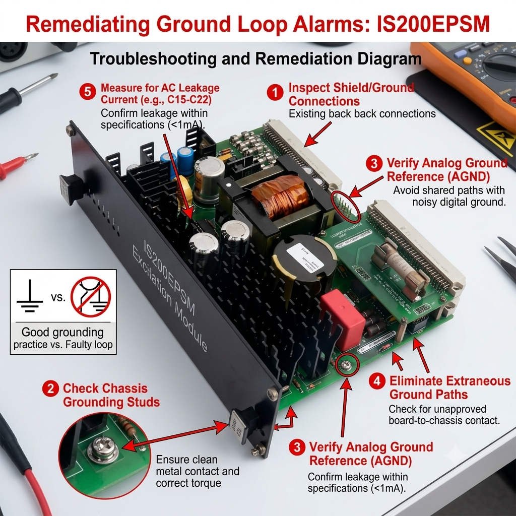
Fix Ground Loop Alarms on GE IS200EPSM Excitation Modules

Fix Ground Loop Alarms on GE IS200EPSM Excitation Modules

How Ground Potential Differences Impact the Stability of the GE IS200EPSM Module

In high-power industrial automation, proper grounding topology is just as vital as input voltage quality. The GE IS200EPSM power supply module acts as a primary energy source within the EX2100 excitation platform. However, voltage potential differences between the DCS electronic ground and Protective Earth (PE) frequently degrade system stability. This technical review explores how ground loops introduce common-mode noise and compromise critical processor power networks.

Fix Ground Loop Alarms on GE IS200EPSM Excitation Modules

Fix Ground Loop Alarms on GE IS200EPSM Excitation Modules

The Architecture and Functional Value of the IS200EPSM

The IS200EPSM provides highly regulated low-voltage DC outputs directly to internal control electronics and sensitive I/O pathways. Its advanced power-conversion circuitry depends heavily on a clean, consistent reference potential to maintain tight regulation parameters. In continuous-process plants, this stability remains paramount for safeguarding against turbine trips and operational asset dropouts. Therefore, the module functions as the foundational electrical backbone for the wider system logic controller.

The Mechanics of Common-Mode Noise and Reference Drift

A significant voltage potential difference often arises when control cabinets lie far apart from primary substations. When the electronic ground shifts relative to PE, dangerous currents flow backward through data cable shields. Consequently, this circulating common-mode current generates electromagnetic interference that shifts the zero-volt baseline reference. As a result, processors misinterpret logic thresholds, triggering intermittent data packet losses, false high alarms, or random watchdog time-outs.

Field data indicates that grounding anomalies account for over 35% of unexplained controller resets in legacy systems. The internal filtering networks of the IS200EPSM can clamp minor transient currents effectively. However, continuous common-mode voltage stress above one volt exceeds the dampening limits of standard isolation transformers. This ongoing stress forces sensitive multi-layered boards to process high-frequency noise instead of clean power variables.

Surge Tolerance Limits and Semiconductor Degradation

Equipotential bonding directly influences how a power module handles lightning transients and massive motor switching events. If the control infrastructure lacks an integrated ground path, surge energy seeks alternative routes through internal semiconductor elements. This diverted energy creates severe thermal strain inside the module’s primary switching transistors and smoothing capacitors. Over time, this stress drastically reduces the mean time between failures (MTBF) for the power supply hardware.

Selecting and Validating the Correct Hardware Revision

When engineering system retrofits, maintenance teams must carefully match original bill-of-materials (BOM) part numbers. The IS200EPSM line incorporates distinct internal grounding configurations across different manufacturing series. Older system revisions may utilize isolated ground returns that conflict directly with modern, interconnected backplane frameworks. Procurement managers should cross-reference compatibility metrics through expert distributors like Powergear X Automation Limited to avoid startup logic faults.

Field Procedures for Grounding Diagnostics and Audits

  • Pre-Commissioning Test: Measure both AC and DC voltage between the electronic ground busbar and the cabinet PE frame.
  • ⚙️ Single-Point Alignment: Verify that the control system connects to the main facility grounding grid at exactly one point.
  • 🔧 Shield Termination Audit: Ensure instrument cable shields terminate strictly according to manufacturer instructions to avoid parallel paths.

Expert Implementation Analysis from Powergear X Automation Limited

At Powergear X Automation Limited, we emphasize that replacing a module rarely resolves structural grounding defects. In our field experience, many recurring “hardware failures” disappear entirely once engineers correct high-impedance bonding joints. We recommend maintaining strict compliance with IEEE 1100 and IEC 60364 industrial control system standards during turnarounds. To explore our full catalog of certified components and access specialized technical advice, visit us at https://www.powergearx.com/.

Application Scenario: Gas Turbine Excitation Retrofit

During a major petrochemical refinery modernization project, technicians installed a new IS200EPSM power card. Soon after, the system experienced recurring, unexplained communication drops between the controller and the I/O racks. Diagnostic tracking revealed a 4.8V potential difference between the remote panel ground and the main plant grid. By establishing an equipotential bonding network across the platforms, the engineering team stabilized the communication links instantly.

Frequently Asked Questions (FAQ)

1. What maximum voltage between electronic ground and PE is acceptable for stable operation?
For optimal stability, the voltage difference should remain below 0.5VAC and 1.0VDC. Any steady-state reading exceeding 1.0V requires immediate investigation, as it can cause analog signal drift and logic errors.

2. Can an existing ground loop slowly damage internal components without triggering an immediate alarm?
Yes, ground loops generate continuous high-frequency noise that forces internal filtering components to operate much hotter. This extra thermal load accelerates the dry-out process of electrolytic smoothing capacitors, causing premature module failure months later.

3. Should I ground the instrument cable shield at both ends when using this module?
No, grounding a signal shield at both ends creates a physical parallel path for ground currents to circulate. Always ground the shield at one designated reference point—typically the marshalling cabinet side—to avoid corrupting the 4-20mA loop values.

Back to Top
Product has been added to your cart