
Upgrading to CI520V1: Solving Component Obsolescence in DCS
Strategic Migration with ABB CI520V1: Ensuring Lifecycle Continuity in Industrial Automation
Enhancing System Reliability via Modern Communication Interfaces
The ABB CI520V1 represents a critical evolution in communication interface technology for distributed control systems (DCS). While legacy hardware often faces the threat of obsolescence, the V1 update serves as a high-reliability bridge for aging infrastructure. Industries like oil and gas or chemical processing rely on these modules to maintain connectivity without expensive full-scale upgrades. Therefore, the primary value of the CI520V1 lies in securing long-term operability through modernized hardware architecture.
ABB CI520V1 Guide Lifecycle Support for Control Systems
Technical Comparison: CI520 vs. CI520V1 Lifecycle Management
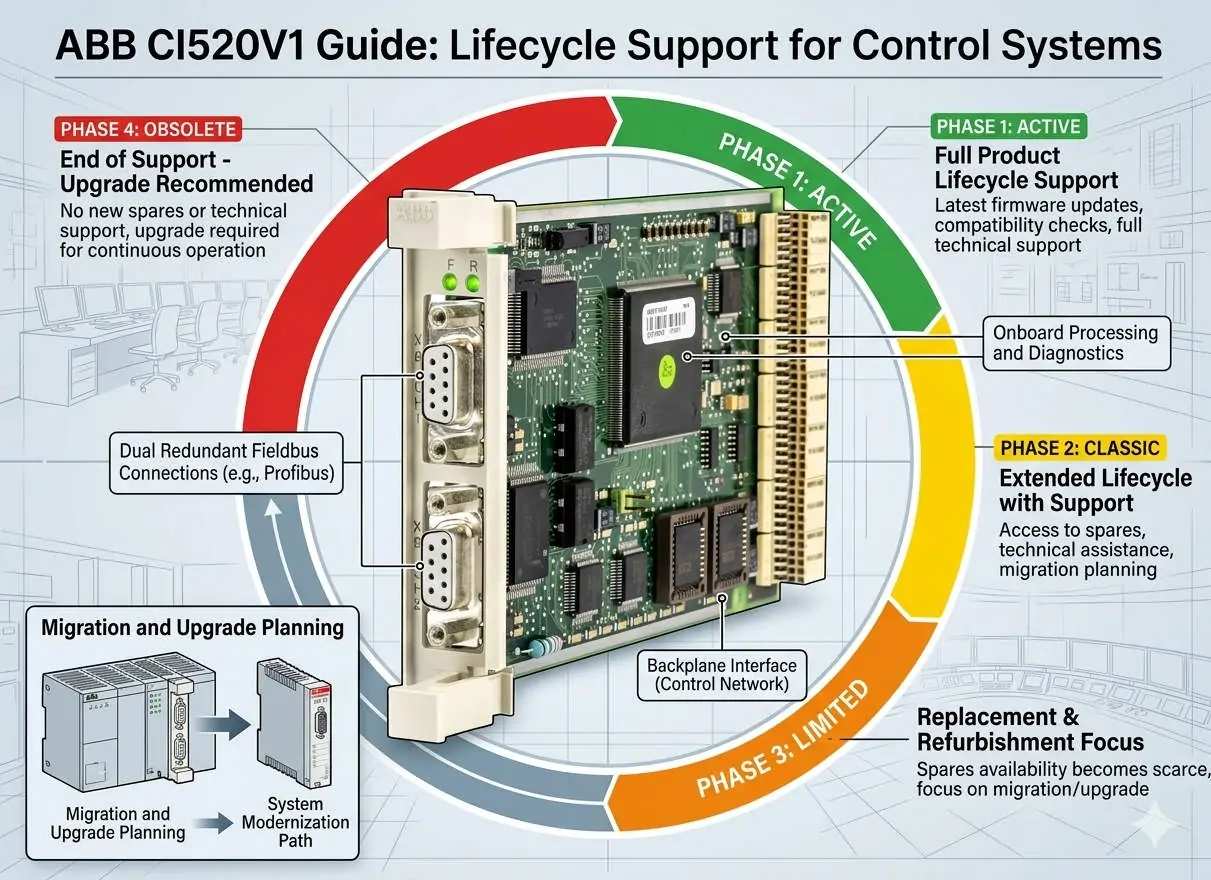
The most significant distinction between the original CI520 and the CI520V1 is component availability. The legacy CI520 relies on electronic parts that are now discontinued by global manufacturers. In contrast, the CI520V1 utilizes RoHS-compliant, actively supported components to align with modern supply chain standards. As a result, plants can mitigate the risk of extended downtime caused by hardware shortages. This shift ensures that critical spare parts remain accessible for the next decade of operation.
Optimizing Signal Integrity and Electrical Robustness
In harsh factory automation environments, electromagnetic interference (EMI) frequently compromises data transmission. The CI520V1 addresses this by incorporating improved Electromagnetic Compatibility (EMC) tolerance. It provides superior resistance to transients and electrical noise generated by variable frequency drives (VFDs) or high-current motors. Moreover, this enhanced robustness leads to better fault predictability and reduces the occurrence of intermittent communication errors that plague legacy systems.
Seamless Integration and Firmware Compatibility Requirements
The CI520V1 maintains protocol-level backward compatibility, which simplifies the migration process for most ABB control systems. Engineers usually do not need to rewrite complex application logic or communication blocks. However, subtle differences in firmware behavior regarding timeout handling or diagnostic reporting may exist. Consequently, Powergear X Automation Limited recommends conducting validation tests in safety-critical systems. This step ensures that the newer hardware revision integrates perfectly with the existing controller’s firmware environment.
Precision Installation and Maintenance Best Practices
Replacing a legacy module requires more than just physical swapping to ensure peak performance. Technicians should treat the upgrade as an opportunity to audit the entire communication loop. Improper grounding often masks issues that newer, more sensitive modules might detect as faults. Consider these essential technical steps:
- ✅ Verify that the controller firmware version supports the V1 hardware revision.
- ✅ Inspect cable shielding and ensure single-point grounding to prevent noise loops.
- ✅ Confirm the specific backplane requirements before attempting any module replacement.
- ✅ Test communication stability under full industrial load conditions.
Strategic Insights from Powergear X Automation Limited
At Powergear X Automation Limited, we believe that proactive hardware management is superior to reactive repair. Waiting for a CI520 failure in a petrochemical plant can result in losses exceeding the cost of the module by a factor of a thousand. We suggest a phased replacement strategy where the CI520V1 replaces older units during scheduled maintenance windows. This approach aligns with modern asset management strategies and protects the plant against sudden market shortages of discontinued components.
Industrial Application Scenarios and Solutions
- Oil & Gas Refineries: Maintaining high-speed data links between remote I/O stations and the central DCS.
- Chemical Processing: Ensuring signal integrity in environments with high electrical noise and strict safety protocols.
- Legacy Power Plants: Extending the life of 15-year-old control cabinets by replacing obsolete communication interfaces.
Technical Maintenance FAQ
Q: Can the CI520V1 be hot-swapped while the system is under live load?
While many ABB backplanes support hot-swapping, it depends on the specific controller configuration and mounting base. We strongly advise powering down the module slot before replacement to avoid inrush current damage or backplane arcing, unless your specific documentation confirms hot-swap support.
Q: What is the most common error when upgrading from the older CI520?
The most frequent issue is a “Module Not Detected” error, which usually stems from outdated controller firmware. Even if the wiring is identical, the CPU must be updated to recognize the new hardware revision ID of the V1 module.
Q: Does the V1 version offer any speed advantages over the original module?
Functional speed remains identical to ensure logic timing consistency. The “V1” designation focuses on reliability, EMC protection, and component longevity rather than increasing the baud rate or data throughput.
For more technical specifications and to secure your inventory of high-quality interface modules, please visit the official Powergear X Automation Limited website.
