Over 50,000 hot-selling automation module components.
Bently Nevada 3500-42M Gap Voltage Cable Length Impact Guide_

Bently Nevada 3500/42M Gap Voltage & Cable Length Impact Guide

Impact of Probe Cable Length Errors on Gap Voltage in Bently Nevada 3500/42M Systems

In modern industrial automation, machinery protection systems safeguard critical rotating equipment across heavy processing industries. Vibration monitoring systems rely heavily on precise eddy current proximity transducers to track shaft movement. The Bently Nevada 3500/42M Proximity Monitor requires strict length matching between the proximity probe, extension cable, and Proximitor sensor. Mismatches directly shift the DC bias gap voltage and undermine overall measurement accuracy. Powergear X Automation presents this technical guide to help field engineers prevent diagnostic errors and optimize control systems performance.

Bently Nevada 3500-42M Gap Voltage Cable Length Impact Guide_

Bently Nevada 3500-42M Gap Voltage Cable Length Impact Guide_

Understanding Proximity Transducer System Architecture

Eddy current transducer systems function as calibrated, high-frequency tuned resonant circuits rather than simple electrical wiring. Standard installations utilize either a 5-meter or 9-meter overall system length. A 5-meter system typically combines a 1-meter probe with a 4-meter extension cable. Conversely, a 9-meter system pairs a 1-meter probe with an 8-meter extension cable. The Proximitor sensor contains internal oscillator components configured specifically for these fixed cable lengths. Therefore, mixing mismatched components alters the electrical impedance and distorts the output curve.

How Cable Length Mismatches Shift Gap Voltage Output

The 3500/42M monitor module reads raw voltage signals directly from the Proximitor sensor. However, using incorrect cable lengths fundamentally skews the sensor’s voltage-to-distance conversion ratio. A standard target gap setting generates approximately -10V DC across a 2mm linear operating range. Misconfiguring a 9-meter physical system as a 5-meter setup in the rack software alters this output baseline. As a result, actual gap voltage might drift toward -7V DC or -13V DC, shifting the measurement out of the calibrated linear window.

Consequences of Linear Range Offsets on Machinery Protection

Operating outside the calibrated linear zone creates severe operational risks for turbomachinery. If the gap voltage remains within the margin, the monitor OK LED stays green and vibration values update. However, the available linear headroom drops significantly, increasing the risk of signal saturation during high-vibration events. If the gap voltage strays beyond linear limits, the channel triggers false alarms or records misleadingly low vibration amplitudes. Consequently, plant operators might miss critical shaft movement during heavy equipment startup cycles.

API 670 Standard Compliance for Factory Automation

Machinery protection in continuous processing plants must strictly adhere to the API 670 standard. According to industry reports, improper sensor calibration accounts for over 15% of false machinery shutdown trips globally. API 670 explicitly mandates that proximity probes, extension cables, and Proximitors remain fully matched and factory-calibrated. Engineers must never interchange 5-meter and 9-meter system components arbitrarily during emergency maintenance. Procurement teams must verify complete system part numbers before issuing replacement purchase orders.

Step-by-Step Field Commissioning and Verification Sequence

  1. Inspect Physical Hardware: Check the part numbers on the proximity probe, extension cable, and Proximitor sensor to confirm total physical system length.
  2. Verify Software Configuration: Connect to the 3500 Rack Configuration Software and verify that the selected transducer type matches the installed physical hardware length.
  3. Measure Physical Mechanical Gap: Set the probe mechanical clearance using feeler gauges or a dial indicator to the specified target distance.
  4. Confirm Measured DC Voltage: Read the channel gap voltage on the module front panel or software interface to ensure it registers near -10V DC.

Field Installation Practices and Cable Routing

Proper physical installation prevents signal degradation in noisy factory automation environments. Extension cables routed near turbomachinery experience high mechanical vibration and electromagnetic interference. Engineers should maintain minimum cable bend radii specified by the manufacturer and avoid sharp 90-degree turns. Furthermore, field technicians must secure extension cables in rigid metallic conduits and ground the shielding strictly according to facility EMC guidelines. Unsecured cables vibrate freely, inducing false high-frequency noise spikes on the PLC registers.

B2B Procurement and Hardware Replacement Guidelines

Replacing legacy Bently Nevada hardware requires a thorough review of existing control panel documentation. Maintenance teams often assume that probes with identical mounting threads are universally interchangeable. However, swapping a 5-meter probe into a 9-meter Proximitor circuit ruins system calibration. When sourcing replacement parts for factory automation infrastructure, procurement managers must evaluate CPU firmware, rack backplane compatibility, and system length parameters. Verifying these configurations offline prevents extended plant downtime during scheduled turnarounds.

Application Scenario: Gas Turbine Shaft Vibration Troubleshooting

During a planned overhaul of a power generation plant, technicians replaced a damaged 3300 XL proximity probe on a gas turbine shaft. Shortly after startup, the 3500/42M monitor generated a persistent gap voltage alarm on Channel 2, reading -5.2V DC instead of the nominal -10V DC target, although the shaft mechanical clearance measured correctly.

The engineering team investigated the installation and discovered that a 9-meter replacement probe assembly had been connected to an existing 5-meter Proximitor sensor. To rectify the issue, the team replaced the Proximitor with a verified 9-meter model and updated the 3500 Rack Configuration software settings accordingly. The gap voltage immediately stabilized at -9.8V DC, restoring full linear measurement range and bringing the machinery protection system back into full API 670 compliance.

For reliable hardware sourcing and expert technical support on Bently Nevada monitoring components, visit Powergear X Automation to find high-performance solutions for your plant control systems.

Frequently Asked Questions (FAQ)

Q1: Can I adjust the 3500/42M software settings to correct a physical cable length mismatch?
No. Changing software parameters cannot compensate for physical impedance errors in the Proximitor circuit. You must match the physical probe, cable, and Proximitor length before updating the software configuration.

Q2: How does incorrect gap voltage affect overall vibration reading accuracy?
An incorrect gap voltage pushes the probe operation toward the non-linear edges of its calibration curve. This causes the system to either attenuate or exaggerate actual vibration amplitudes during operation.

Q3: What is the primary operational difference between a 5-meter and a 9-meter proximity system?
The primary difference lies in the internal electrical tuning of the Proximitor sensor. The 9-meter Proximitor accounts for additional electrical resistance and capacitance inherent in the longer extension cable.

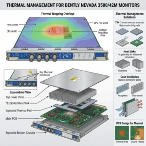
Thermal Management for Bently Nevada 3500-42M Monitors

Thermal Management for Bently Nevada 3500/42M Monitors

Thermal Management Risks for Bently Nevada 3500/42M Proximitor Seismic Monitors

Critical Role of Vibration Monitoring in Industrial Automation

The Bently Nevada 3500/42M serves as a vital component in high-reliability vibration and position monitoring. In sectors like oil and gas or power generation, this module protects critical rotating machinery. However, thermal stress can compromise its signal accuracy. Excessive heat directly undermines system stability. As a result, operators may face false alarms or missed mechanical faults.

Thermal Management for Bently Nevada 3500-42M Monitors

Thermal Management for Bently Nevada 3500-42M Monitors

Technical Impact of Overheating on Signal Integrity

The standard operating range for the 3500/42M typically spans from 0°C to 65°C. When internal temperatures exceed these limits, signal conditioning circuits begin to drift. Moreover, high heat accelerates the aging of electrolytic capacitors. This degradation shortens the module’s overall lifespan significantly. In many refinery environments, poor ventilation pushes temperatures above 70°C, causing intermittent channel dropouts.

Operational Risks and Response Stability Challenges

Heat introduces electrical noise and ADC instability within the monitor’s analog front-end. Consequently, proximitor signal scaling may drift away from calibrated values. These deviations often lead to false high-vibration alarms. Such errors trigger unnecessary machinery shutdowns and lost production time. Conversely, drift might mask early-stage bearing wear. This delay turns minor maintenance into a catastrophic unplanned outage.

System-Level Reliability in Rack Architectures

The 3500 system architecture relies on seamless integration between modules and power supplies. An overheating 3500/42M module increases the total thermal load of the entire rack. This heat transfer can trigger system-wide watchdog resets. Furthermore, redundant configurations suffer when thermal stress affects both primary and backup channels simultaneously. Maintaining a balanced thermal profile is essential for modern control systems.

Installation and Maintenance Best Practices

Field experience suggests that most overheating issues stem from installation errors rather than hardware defects. Engineers must prioritize cabinet thermal management to ensure longevity. Proper airflow prevents heat pockets from forming around sensitive electronics. In addition, dust accumulation acts as a thermal insulator, blocking essential cooling paths.

  • ✅ Maintain minimum airflow clearance at the top and bottom of the rack.
  • ✅ Avoid placing racks near heat sources like VFD panels or transformers.
  • ✅ Inspect and clean cabinet air filters monthly in dusty environments.
  • ✅ Utilize positive-pressure cabinets to keep internal components clean.
  • ✅ Verify total rack power load against the Power Supply Unit (PSU) rating.

Strategic Selection and Compatibility Insights

The 3500/42M offers backward compatibility within the 3500 rack series. However, hardware revisions and firmware versions must align for optimal performance. Older racks often lack the optimized airflow designs found in newer chassis. Therefore, users should verify rack revision levels before performing upgrades. Ignoring environmental conditions during selection often leads to premature module failure.

Expert Commentary from Powergear X Automation Limited

At Powergear X Automation Limited, we believe thermal management is a core part of machinery protection strategy. High-performance modules like the 3500/42M require stable environments to deliver precision. We often see random alarms disappear simply by redistributing modules to improve airflow. Treating cooling as an afterthought is a risk no plant manager should take. For high-quality automation parts and expert support, explore our solutions at Powergear X Automation Limited.

Application Scenarios and Solutions

  • High-Speed Turbines: Requires precise displacement monitoring where even 1°C of drift can trigger a safety trip.
  • Refinery Compressors: Utilizes seismic monitoring in harsh, ambient heat conditions requiring active cooling.
  • Remote Pumping Stations: Depends on self-diagnostics to alert maintenance teams of thermal rising before a fault occurs.

Frequently Asked Questions (FAQ)

Q: How can I detect overheating before it causes a system shutdown?
We recommend using thermal imaging cameras during routine inspections. This technique reveals hot spots that standard temperature sensors might miss. Also, monitor the “System Event List” for frequent self-test warnings or intermittent channel status changes.

Q: Will adding more fans to the cabinet always solve the problem?
Not necessarily. If the internal rack airflow is blocked by cabling or overpacking, external fans won’t help. You must ensure a clear path for air to move through the module slots themselves.

Q: Does the 3500/42M have a built-in automatic shutdown for heat?
The module includes self-protection logic, but it usually triggers a “Module Fault” rather than a clean shutdown. By the time this happens, your machinery protection is already compromised. Prevention through environmental control is the only safe approach.

Looking for reliable Bently Nevada modules or expert advice on rack configuration? Visit Powergear X Automation Limited today for global shipping and technical excellence.

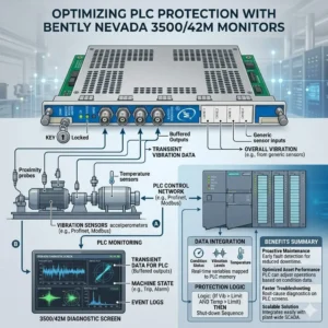
Optimizing PLC Protection with Bently Nevada 3500-42M Monitors

Optimizing PLC Protection with Bently Nevada 3500/42M Monitors

Optimizing Machinery Protection with Bently Nevada 3500/42M Proximitor Seismic Monitors

The Vital Role of 3500/42M in Industrial Automation

The Bently Nevada 3500/42M serves as a critical guardian for high-value rotating assets. It integrates multiple sensor inputs to facilitate precise alarm decisions across various industrial sectors. This module significantly enhances safety in oil and gas, petrochemical, and power generation environments. By reducing false trips, it ensures continuous production while maintaining strict safety standards. Consequently, plants can avoid the massive financial losses associated with unplanned downtime.

Optimizing PLC Protection with Bently Nevada 3500-42M Monitors

Optimizing PLC Protection with Bently Nevada 3500-42M Monitors

Advanced Boolean Logic for Tailored Control Systems

The 3500/42M supports sophisticated Boolean alarm logic, including OR, AND, and NOT configurations. Engineers use OR logic for early fault detection when any single bearing exceeds limits. Conversely, AND logic requires multiple simultaneous conditions, which effectively filters out transient noise during machine startup. Furthermore, NOT logic allows operators to suppress specific alarms during necessary maintenance intervals. These flexible configurations ensure that the monitor reacts only to genuine mechanical threats.

Enhancing Reliability Through Voting and Time Delays

Reliability improves further through the integration of time delays and channel voting behaviors. For instance, a 2-out-of-3 (2oo3) logic prevents a single faulty sensor from triggering a full system shutdown. This approach aligns perfectly with API 670 standards for machinery protection systems. As a result, the 3500/42M balances the need for sensitivity with the necessity of operational stability. Proper delay settings prevent nuisance trips caused by momentary process disturbances.

Strategic Multi-Channel Integration for Factory Automation

Each module processes both proximity and seismic inputs, allowing for comprehensive multi-channel correlation. Instead of viewing sensors in isolation, engineers can analyze radial and axial vibration together. This holistic view significantly improves the accuracy of fault diagnosis and predictive maintenance. Moreover, integrating these signals into a broader DCS or PLC network streamlines plant-wide monitoring. Precise data correlation extends equipment life by preventing both under-protection and unnecessary mechanical stress.

Best Practices for Field Commissioning and Maintenance

Successful deployment requires more than just hardware installation; it demands rigorous logic validation. During commissioning, experts at Powergear X Automation Limited recommend avoiding default OR logic for all shutdown parameters. Instead, use simulated signals to test the response of every logic gate before the actual startup. Additionally, ensure that maintenance bypasses are clearly visible on human-machine interfaces (HMI). Proper grounding and shielded cabling remain essential to prevent intermittent signals in high-vibration zones.

Author Insights: The Future of Machinery Protection

At Powergear X Automation Limited, we believe the 3500/42M represents a shift toward more intelligent protection. Modern industry reports from MarketsandMarkets suggest the vibration monitoring market will grow as AI integration increases. However, the fundamental reliability of hardware-based logic remains the gold standard for safety. We advise users to maintain strict firmware version control to ensure seamless backward compatibility. Investing in high-quality monitoring today prevents catastrophic mechanical failures tomorrow.

Industrial Solution Scenarios

  • Gas Turbine Protection: Use AND logic with 2oo3 voting to protect turbines from excessive vibration during load changes.
  • Remote Pumping Stations: Implement OR logic for early alerts to dispatch maintenance teams before a failure occurs.
  • Refinery Compressors: Combine NOT logic with digital inputs to safely calibrate probes without tripping the unit.

Technical Implementation Checklist

  • ✅ Verify firmware compatibility between the 3500/42M and the existing 3500 rack.
  • ✅ Use single-point grounding for all shielded cables to eliminate ground loops.
  • ✅ Configure “Alert” levels with OR logic for maximum sensitivity.
  • ✅ Configure “Danger” levels with AND logic to ensure high-integrity shutdowns.

Frequently Asked Questions (FAQ)

Q: How does the 3500/42M improve Mean Time Between Failures (MTBF)?
By using AND logic and voting, the system filters out “nuisance” data that would otherwise cause unnecessary wear from frequent startups and stops. This stabilization allows the machinery to operate within its design limits more consistently.

Q: Can I mix different sensor types on a single 3500/42M module?
Yes, the 42M is highly versatile. It can process signals from Proximitor sensors, velocity transducers, and accelerometers simultaneously, provided the configuration software is updated to match the specific transducer constants.

Q: What is the most common error during module replacement?
Failure to upload the specific configuration file from the old module often leads to incorrect logic behavior. Always back up your 3500 rack configuration using the Bently Nevada software before attempting a hardware swap.

For high-quality industrial spare parts and expert technical support, visit the official Powergear X Automation Limited website today.

Bently Nevada 330500 Sensor Diagnostics for Industrial Automation

Bently Nevada 3500/42M Wiring & Configuration for 330500 Sensors

Integrating 330500 Proximitor Sensors with Bently Nevada 3500/42M Monitors

The Bently Nevada 3500 Series remains the global benchmark for machinery protection in industrial automation. Specifically, the 3500/42M Proximitor/Seismic Monitor serves as a critical bridge between physical hardware and digital insights. Connecting the 330500 (3300 XL Proximitor) sensor correctly is vital for monitoring high-speed rotating assets. This guide outlines the technical procedures and professional best practices for a seamless integration.

Bently Nevada 330500 Sensor Diagnostics for Industrial Automation

Core Components of the 3300 XL Proximitor System

The 330500 Proximitor is the “brain” of the 3300 XL 8mm transducer system. It converts the radio frequency (RF) signal from the probe into a usable voltage output. This system typically includes the proximity probe, an extension cable, and the Proximitor sensor itself. Because these components are calibrated together, mixing different lengths or brands can lead to significant linearity errors in your data.

Technical Capabilities of the 3500/42M Module

The 3500/42M is a versatile four-channel module designed for diverse factory automation environments. It processes signals for radial vibration, axial position, and even eccentricity. In my experience at Powergear X Automation, we often see users overlook the module’s programmable nature. This flexibility allows it to adapt to various transducers, but it requires precise software configuration to ensure machine safety.

Step-by-Step Wiring for Reliable Signal Integrity

Proper wiring prevents signal interference and ensures the longevity of your control systems. Most Bently Nevada systems follow a standard three-wire color code, though you should always verify with the specific datasheet.

Connect Power: Link the module’s -24 VDC terminal to the Proximitor’s power input (usually the red wire).

Attach Signal: Route the white signal wire to the designated channel input on the 3500/42M.

Establish Common: Connect the black common wire to the COM terminal to complete the circuit.

Grounding and Shielding for Industrial Environments

Electrical noise is the primary enemy of precision vibration monitoring. You must ground the cable shield at the 3500 rack end only. This prevents ground loops which cause erratic readings. Furthermore, always run sensor cables through dedicated conduits. Separation from high-voltage power lines is essential for maintaining a clean signal-to-noise ratio.

Software Configuration and Calibration Procedures

Physical wiring is only half the battle; the software must match the hardware. Use the 3500 Rack Configuration Software to set the sensor type to “3300 XL 8 mm.” Ensure the scale factor reflects the standard 200 mV/mil (7.87 V/mm). If these parameters are incorrect, your alarms will not trigger during a genuine mechanical fault, risking catastrophic equipment failure.

Professional Commissioning and Field Validation

Testing is the final hurdle before live operation. We recommend verifying the “Gap Voltage” while the machine is at rest. A healthy gap typically reads around -10 VDC. If the voltage is near 0 or -24 VDC, you likely have a wiring fault or a probe clearance issue. Documenting these initial values creates a baseline for all future predictive maintenance efforts.

Author Insights from Powergear X Automation

At Powergear X Automation, we observe a growing trend toward integrating 3500 systems with broader DCS and IoT platforms. While the 3500/42M provides hardware-level protection, the real value lies in the data it generates. We suggest always using genuine Bently Nevada components to maintain system certification and ensure the highest level of E-E-A-T (Experience, Expertise, Authoritativeness, and Trustworthiness) in your maintenance strategy.

Technical Best Practices Checklist

  • ✅ Use calibrated torque wrenches for probe mounting to avoid housing damage.
  • ✅ Verify that extension cable lengths match the Proximitor’s specific calibration (e.g., 5m or 9m).
  • ✅ Inspect BNC connectors for moisture or debris before final assembly.
  • ✅ Label every wire clearly at both ends to simplify future troubleshooting.
  • ✅ Confirm that the Proximitor mounting plate is electrically isolated from the machine frame.

Solutions for Common Installation Scenarios

Scenario: High Temperature

Recommended Action: Use specialized high-temp extension cables and ceramic-tipped probes.

Scenario: Long Distance

Recommended Action: Ensure the total loop resistance does not exceed the 3500/42M limits.

Scenario: Corrosive Area

Recommended Action: Install Proximitors inside NEMA 4X or IP66 rated stainless steel enclosures.

For high-quality components and expert technical support for your next project, visit Powergear X Automation to explore our comprehensive inventory of monitoring solutions.

Frequently Asked Questions (FAQ)

Q: Can I use a 3300 XL probe with an older 7200 series Proximitor?

A: No. The internal circuitry and RF frequencies differ between generations. Mixing components leads to non-linear output and will compromise your machinery protection system’s accuracy.

Q: Why is my gap voltage reading -24V constantly after installation?

A: This usually indicates an “Open Circuit.” Based on field experience, check for a snapped extension cable or a loose connection at the Proximitor terminal block.

Q: How often should I recalibrate the 3500/42M and 330500 system?

A: Industry standards like API 670 suggest a full loop check every 18 to 24 months. However, verify the calibration anytime you replace a probe or extension cable.

DCS Integration Choosing 3500-42M Communication Gateway or Analog

DCS Integration: Choosing 3500/42M Communication Gateway or Analog

Communication Gateway vs. 4–20 mA: The Best Way to Transfer Bently Nevada 3500/42M Data to a DCS

The Bently Nevada 3500/42M Proximitor/Seismic Monitor is a cornerstone of critical machinery protection in industrial automation. This robust module reliably manages vibration and position data. A critical engineering decision, however, is determining the optimal path to transmit this protection data to a central Distributed Control System (DCS). Should you rely on the legacy 4–20 mA analog output, or is a modern digital communication gateway the definitive solution?

This article, brought to you by Powergear X Automation, dissects these two options. We will explore their technical capabilities and limitations, providing a clear recommendation to support your factory automation and control systems strategy.

DCS Integration Choosing 3500-42M Communication Gateway or Analog

Understanding the Essential Data from the 3500/42M

The 3500/42M module generates complex data vital for both protection and condition monitoring. The module processes raw sensor input to provide several key metrics.

  • Primary Measurement Values: This includes proximity (gap) or seismic vibration measurements.
  • Processed Variables: Operators rely on calculated values like Overall Vibration, Peak-to-Peak amplitude, $1\times$ and $2\times$ amplitude components, and DC Gap voltage.
  • Protection Status: Crucially, the module issues trip statuses such as OK, Alert, and Danger.
  • Diagnostic Information: The module provides internal health and system diagnostic data accessible via the 3500 rack backplane.

To effectively integrate this into a DCS, the chosen method must efficiently deliver the required data points and maintain adequate update rates.

Option 1: Utilizing 4–20 mA Analog Outputs

The 4–20 mA loop represents a traditional and highly reliable method for data transfer. It converts a measured variable into a proportional current signal.

How the 4–20 mA Output Works

To use this option, the 3500 rack requires optional I/O modules, specifically the Bently Nevada 3500/92 or 3500/96 Analog Output modules. Each analog channel is configured to represent one selected variable—for instance, the overall vibration level—as a continuous 4–20 mA current signal.

Advantages of Analog Transfer

  • Simplicity and Universality: The DCS or PLC (Programmable Logic Controller) requires only standard analog input cards, which are universally supported.
  • Noise Resistance: The current-based signal is inherently resistant to electrical noise over long cable runs.
  • Electrical Isolation: This approach offers excellent isolation between the protection system and the control system.

Limitations of Analog Transfer

However, the 4–20 mA method presents significant constraints when dealing with modern machinery monitoring needs.

  • Single-Variable Constraint: You can transmit only one variable per channel. To get overall vibration and DC Gap, you need two separate analog loops.
  • Data Exclusion: Alarm statuses, event data, diagnostic information, and essential waveform or spectrum data are entirely lost.
  • High Wiring Complexity: A large installation requiring dozens of variables translates into a complex, costly, and resource-intensive wiring process involving numerous analog input cards.
  • Resolution and Speed: The resolution is limited by the DCS/PLC analog-to-digital converter, and the update rate is relatively slow compared to digital protocols.

Use Case: Choose 4–20 mA only if you need minimal data integration, such as displaying the overall vibration value for basic trending on a DCS faceplate.

Option 2: Leveraging a Communication Gateway

For comprehensive integration and modern maintenance practices, a digital communication gateway is the superior solution. This approach transforms the protection system data into a standardized digital protocol.

How Digital Gateway Communication Works

Bently Nevada offers solutions like the 3500/95 or 3500/91 Ethernet Communication Gateway modules. These modules capture all internal data from the 3500 rack via the backplane and present it using industrial protocols like Modbus TCP/RTU, OPC UA, or other Ethernet-based standards.

Advantages of Digital Gateway Transfer

The digital gateway overcomes all the limitations of the analog approach, providing a future-proof link.

  • Full Data Access: Access to all measurement parameters from every channel, not just one processed value.
  • Critical Status Information: Includes all crucial data points: ✅ Alarm statuses (Alert/Danger trips) ✅ Channel OK status ✅ Configuration and system diagnostics
  • High Performance: Features a high data update rate, suitable for detailed trending and fast-acting alarms.
  • Scalability and Efficiency: A single Ethernet cable replaces dozens or hundreds of analog signal wires, drastically reducing installation complexity and cost.
  • Monitoring Platform Support: Facilitates integration with specialized condition monitoring systems, such as GE’s System 1 platform.

Limitations of Digital Gateway Transfer

This option is not without its own requirements.

  • Increased Configuration: Requires networking knowledge and protocol configuration (e.g., Modbus address mapping).
  • DCS/Network Dependency: The DCS or SCADA system must natively support the chosen industrial protocol (e.g., Modbus TCP).
  • Network Reliability: Performance depends entirely on the stability and reliability of the industrial network infrastructure.

Use Case: Choose a communication gateway when multiple variables are required, diagnostic integration is essential, or when transmitting a large number of measurement points.

Best Practice Recommendation and Expert Insight

In the landscape of modern industrial automation, our recommendation is decisive: The Communication Gateway is the preferred solution.

The industry trend, validated by reports from ISA and MarketsandMarkets, shows a clear shift toward digital integration for its scalability and comprehensive data access. While 4–20 mA has a place in legacy or extremely basic systems, it fails to meet the data demands of predictive maintenance and holistic asset management.

⚙️ Use 4–20 mA for:

  • Minimalist Requirements: Displaying only one single, slow-changing overall value.
  • Legacy Systems: Facilities where existing wiring and control systems lack networking capability.

🔧 Use a Communication Gateway for:

  • Comprehensive Diagnostics: Accessing all parameters for advanced asset health monitoring.
  • Efficiency and Scalability: Eliminating massive analog card and wiring infrastructure.
  • Modern Standards: Integration with digital protocols in line with modern PLC and DCS architecture.

Author Comment (Powergear X Automation): Relying solely on 4–20 mA for critical machinery data is like buying a Ferrari but only using the speedometer. The true value of the Bently Nevada 3500/42M lies in its full spectrum of data—alarms, diagnostics, and multiple parameters. The communication gateway unlocks this value, making it a crucial component for maximizing machine uptime and embracing the principles of Industry 4.0.

Practical Solution Scenario: Advanced Asset Management

Imagine a large turbine package. The protection system generates eight key values (Overall, 1x, Gap, Phase) for each of the four bearings, plus two thrust position measurements.

  • Analog Scenario: You would need (8 x 4) + 2 = 34 separate analog loops and 34 analog input channels on the DCS. This creates complexity and cost.
  • Digital Gateway Scenario: A single Ethernet cable from the 3500/95 gateway can deliver all 34 values, plus all associated alarm statuses and diagnostic information, using only one DCS network port. This greatly simplifies wiring, reduces hardware cost, and provides richer data for sophisticated analysis in systems like GE’s System 1.

Frequently Asked Questions (FAQ)

Q1: Can I use both 4–20 mA and the Communication Gateway simultaneously?
A: Yes. Many clients choose a hybrid approach. They use the 4–20 mA output for a few primary, overall vibration values needed immediately on the basic DCS Human-Machine Interface (HMI) screen. Meanwhile, the communication gateway provides the full diagnostic dataset to a separate condition monitoring platform (System 1), effectively separating the protection and diagnostic data streams.

Q2: What is the main configuration hurdle when implementing a Communication Gateway?
A: The primary configuration challenge is accurately mapping the Modbus register addresses within the DCS or SCADA system. Each Bently Nevada variable (e.g., Overall Vibration Channel 1) corresponds to a specific register address in the gateway. This mapping must be meticulously configured to ensure the DCS is reading the correct value, requiring close coordination between the machinery protection specialist and the DCS engineer.

Q3: Does the Communication Gateway replace the need for physical relay outputs for trips?
A: No. The communication gateway is primarily for data transfer to the DCS/SCADA system. For critical machinery trip actions, the physical relay outputs (3500/32 Relay Module) must still be used. Protection systems operate independently and rapidly based on hardware logic; digital communication is too slow and network-dependent to be the primary means of shutdown protection.

To learn more about optimizing your machinery protection integration and leveraging the power of industrial communication, visit Powergear X Automation at https://www.powergearx.com/.

Back to Top
Product has been added to your cart