Over 50,000 hot-selling automation module components.
Bently Nevada 3500-22M TDI Modbus TCP Integration Guide

Optimize Vibration Data with Bently Nevada 3500/22M Interface

Seamless Data Integration with the Bently Nevada 3500/22M Transient Data Interface

Bridging the Gap Between Vibration Monitoring and Plant Control

In high-stakes industries like oil and gas or power generation, communication compatibility often creates a technical bottleneck. The Bently Nevada 3500/22M Transient Data Interface (TDI) serves as the vital gateway between 3500 series machinery protection racks and external control systems. By facilitating reliable data extraction, this module allows operators to push critical machinery health insights directly into DCS or SCADA platforms. Consequently, plants can eliminate the need for complex custom middleware while maintaining high-fidelity asset management.
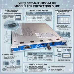
Bently Nevada 3500-22M TDI Modbus TCP Integration Guide

Bently Nevada 3500-22M TDI Modbus TCP Integration Guide

Technical Insights: Mastering Modbus TCP/IP Connectivity

The 3500/22M module utilizes Modbus TCP/IP protocols rather than traditional Modbus RTU serial connections. This shift to an Ethernet-based TCP/IP stack offers significant advantages for modern industrial automation. For instance, it provides higher data throughput and supports multi-client access for remote diagnostics. Therefore, integration with modern Ethernet-based DCS architectures becomes much simpler. However, legacy systems relying on RS-485 Modbus RTU will require an external protocol gateway to bridge the communication gap.

Optimizing Throughput and Reducing Network Latency

Engineers designed the 3500/22M to handle both transient and steady-state high-resolution data. Faster polling cycles through TCP improve real-time vibration monitoring and accelerate alarm response speeds. Nevertheless, heavy network congestion can introduce unwanted latency. To maintain performance, we recommend segmenting condition monitoring traffic via a dedicated VLAN. In our experience at Powergear X Automation Limited, delayed alarms often stem from overloaded plant networks rather than hardware failures within the 3500 rack itself.

System Architecture and Compliance with API 670 Standards

The 3500/22M functions as both a data concentrator and a communication interface for the entire rack. It interfaces with the internal backplane for data acquisition while providing external Ethernet ports for data export. This design effectively separates the deterministic protection system from the analytical monitoring network. As a result, the system maintains strict compliance with API 670 machinery protection standards. This separation ensures that network-level issues do not interfere with critical machine trip functions.

Installation Best Practices for Industrial Environments

Successful deployment of the 3500/22M requires a robust network and electrical design. You should never connect the module directly to a general office LAN. Instead, use industrial-grade switches and establish a dedicated VLAN to prevent broadcast storms. Furthermore, ensure the rack is properly grounded to mitigate electromagnetic interference (EMI). In turbine halls, high-current lines can create noise that leads to “ghost alarms” in the SCADA system if Ethernet cables lack proper shielding.

Evaluating Compatibility for Legacy Brownfield Projects

When upgrading older plants, buyers must verify rack firmware versions before procuring the 3500/22M. While the module is compatible with standard 3500 racks, older systems might not fully exploit TCP-based features. If your current control system is strictly Modbus RTU-dependent, budget for a high-quality industrial TCP-to-RTU converter. This proactive approach prevents unexpected integration costs from exceeding the hardware investment during the commissioning phase.

Expert Commentary from Powergear X Automation Limited

At Powergear X Automation Limited, we believe the 3500/22M is a prerequisite for any facility moving toward Industry 4.0 or digital transformation. The ability to stream high-density vibration data without serial bottlenecks is a game-changer for predictive maintenance. However, we urge engineers to prioritize network security and segmentation. As these interfaces bridge the gap between OT and IT, a secure, isolated communication layer is essential for long-term operational stability.

Application Scenarios and Strategic Solutions

  • Large Compressor Stations: Isolated condition monitoring traffic ensures that transient data does not saturate the primary control network.
  • Petrochemical Refining: Direct integration with Honeywell or Emerson DCS via Modbus TCP simplifies the asset management workflow.
  • Digital Power Plants: Utilizing the TDI for remote diagnostics allows off-site experts to analyze vibration signatures in real-time.

Technical Implementation Checklist

  • ✅ Verify SCADA support for Modbus TCP mapping before installation.
  • ✅ Use shielded Cat6 cables and maintain distance from high-voltage conduits.
  • ✅ Implement an industrial protocol gateway if RS-485 connectivity is mandatory.
  • ✅ Update rack firmware to the latest version to ensure full TDI feature support.

Frequently Asked Questions (FAQ)

Q: Can I use the 3500/22M to replace a 3500/20 Rack Interface Module?
Yes, the 3500/22M is the newer generation Transient Data Interface that provides enhanced Ethernet capabilities. However, you must verify that your configuration software is updated to support the 22M hardware profile to avoid configuration errors.

Q: Why does my SCADA system intermittently lose connection to the TDI?
This is frequently caused by ARP table overflows or broadcast traffic on a shared network. We recommend assigning a static IP address to the 3500/22M and placing it behind a managed industrial switch with IGMP snooping enabled.

Q: Does the 3500/22M support simultaneous connections to System 1 and a third-party PLC?
Yes, the module supports multiple socket connections. This allows Bently Nevada’s System 1 software to collect rich diagnostic data while your plant PLC polls basic alarm registers via Modbus TCP simultaneously.

For more technical specifications and high-performance automation modules, visit the official Powergear X Automation Limited website to view our latest inventory.

Troubleshooting Bently Nevada 3500/22M TDI

Flashing 3500/22M TDI Fault: Causes and Fixes for Communication Module Failure

Decoding the Fault: Why the 3500/22M’s ‘OK’ LED is OFF While ‘TX/RX’ Flashes

The Bently Nevada 3500 Machinery Protection System is a cornerstone of critical asset monitoring in industrial automation. The 3500/22M Transient Data Interface (TDI) module is essential for data exchange and system interface, acting as the primary communication gateway between the rack and external systems, often a DCS or PLC. When its ‘OK’ LED is unlit (OFF) and the ‘TX/RX’ LED is rapidly flashing, it signals a critical state: the module has power and is attempting communication, yet it is fundamentally blocked from achieving a healthy, fully operational status.

This situation demands immediate attention to prevent system downtime. As observed in many factory automation environments, the causes typically fall into software missteps, firmware issues, or subtle hardware failures.

Troubleshooting Bently Nevada 3500/22M TDI

Configuration Mismatches Block Healthy Operation

The most frequent culprit behind a failed ‘OK’ LED is a configuration issue. The module must pass rigorous self-checks against its loaded setup to achieve a healthy state. If the control systems configuration is invalid or incomplete, the module cannot proceed.

Key configuration pitfalls include:

Missing or Corrupted Configuration: The module has no valid or intact operating parameters loaded.

Incorrect Slot Assignment: The physical placement of the module does not match the assigned slot in the configuration software.

System Parameter Discrepancies: A mismatch exists in the configured rack address, essential communication parameters, or the designated TDI role.

The persistent flashing of the ‘TX/RX’ LED in this state shows that the module is still trying to exchange limited packets, perhaps for network discovery, but the system does not recognize it as a properly configured device.

Outdated or Corrupt Firmware Prevents Boot-up

The integrity and compatibility of firmware across the entire 3500 rack are non-negotiable for stable operation. Firmware issues can easily prevent the module from reaching an ‘OK’ status.

Common firmware-related barriers:

Version Incompatibility: The module’s firmware version is obsolete relative to the current rack configuration or the System 1 software.

Firmware Image Corruption: The internal software of the module itself is damaged.

Database Mismatch: The module’s firmware does not align with the 3500 Module Database used by the configuration application.

In these specific scenarios, the system’s protective logic disables the ‘OK’ status. This keeps the module from going online and potentially compromising the integrity of the protection system. This is a crucial safety feature in machinery monitoring.

Subtle Hardware Failures Impact Core Functionality

If software validations all pass, engineers must investigate potential hardware integrity issues. A completely OFF ‘OK’ LED often points to a failure within the physical components.

Hardware failure indicators:

Internal Circuit Board Fault: Failure of core components like memory chips or the processor.

Module Power Rail Issues: Internal power supply regulation failures within the 3500/22M.

Backplane Connector Damage: Bent pins or damaged seating on the module or the backplane slot.

The Author’s Insight: The ‘TX/RX’ LED might still flicker because the basic transmitter/receiver circuitry often operates independently of the main processor’s full operational readiness. This is a valuable diagnostic clue showing that basic I/O power is present.

Backplane Communication Interruptions

The 3500/22M relies on the rack’s backplane for stable internal communication and power distribution. If the backplane link is interrupted, the module cannot successfully achieve a healthy operational state.

Common backplane causes:

Poorly Seated Module: The module is not fully or correctly inserted into the slot.

Contaminated Connectors: Oxidation or foreign debris on the gold-plated connectors.

Faulty Rack Slot: The physical slot on the backplane itself is damaged.

Power Distribution Irregularities: Unstable or insufficient voltage delivered via the backplane.

Even if the module receives enough power to flicker the ‘TX/RX’ LED, a loss of the critical backplane communication path forces the ‘OK’ LED to remain OFF.

External Network Link Faults

The flashing ‘TX/RX’ indicates active attempts to communicate with external systems (like a DCS or a historian). However, if this external link is unstable or incorrectly configured, the module’s initialization sequence can stall.

Potential external communication issues:

Incorrect Network Parameters: Misconfigured IP addresses, baud rates, or protocol settings.

Damaged or Miswired Cable: A fault in the physical Ethernet or serial communication cable.

External System Conflicts: Errors or conflicts when interfacing with external systems, often seen in complex control systems networks.

Rack Interface Module (RIM) Identification Problems

The 3500 Rack Interface Module (RIM) or TDI is responsible for recognizing and managing all other modules in the rack. If the RIM fails to properly identify the 3500/22M, the ‘OK’ status will be suppressed.

Causes related to module recognition:

Incomplete Initialization: The 3500/22M fails to complete its identification handshake with the RIM.

Incorrect Module Sequencing: The physical or configured order of modules is wrong.

RIM Fault: A failure within the Rack Interface Module itself affects module identification services.

Addressing Power Instability Within the Rack

While the flashing ‘TX/RX’ confirms some power is present, insufficient or unstable power can easily prevent the module from completing its resource-intensive boot sequence.

Power supply related reasons:

Weak Rack Power Supply: The overall power supply unit is aged or operating below specification.

Overloaded Power Bus: Too many high-draw modules are installed, straining the power capacity.

Internal Power Distribution Faults: Short circuits or loose wiring within the rack’s power distribution.

Solutions & Next Steps

A systematic troubleshooting approach is key to resolving this critical module state:

✅ Configuration Validation: Always start by verifying the configuration file against the physical installation and ensuring firmware compatibility. ⚙️ Reseating the Module: Power down the rack (if safe) and reseat the 3500/22M module to rule out a loose connection. 🔧 Checking Backplane Integrity: Inspect the backplane slot for any bent pins or contamination. ✅ Communication Path Review: Confirm external network settings (IP, baud rate) are correct and test cables for continuity.

If your team is facing chronic issues with Bently Nevada systems, our experts at Powergear X Automation can provide specialized support and integration services. Visit Powergear X Automation here for advanced troubleshooting guides and system consultation.

Frequently Asked Questions (FAQ)

Q1: The ‘TX/RX’ LED is flashing, but communication software still shows the module offline. Why?

The ‘TX/RX’ LED is a low-level indication that the transmitter and receiver circuits are active and attempting to send or receive data packets. However, if the module’s main processor or its operating system has failed to boot (often due to a configuration or firmware lock-out), the module cannot execute the higher-level application protocol needed to be recognized as ‘online’ by the external monitoring software.

Q2: Does this fault state indicate that my machinery is completely unprotected?

Not necessarily, but it is a serious warning. The 3500/22M is the communication module; its failure means that transient data, alarms, and diagnostics are not being sent to the control room (DCS/Historian). However, the other 3500 protection modules (like the 3500/40 or 3500/50) are typically designed to continue performing their localized monitoring and protective trip functions independently of the 3500/22M’s communication status. You lose visibility and logging, not immediate protection.

Q3: Based on experience, which cause should I check first for the quickest fix?

In our field experience, the single most common and easiest issue to verify is Module Seating/Configuration Mismatch. After a maintenance window or module swap, technicians sometimes overlook a correct reseat or load an old configuration file. Always verify the configuration file’s integrity and the module’s physical seating before moving on to more complex checks like firmware updates or hardware replacement.

Bently Nevada 3500/22M TDI Evaluation for Industrial Automation

Bently Nevada 3500/22M TDI Evaluation for Industrial Automation

Evaluating Your Bently Nevada 3500/22M TDI: Replacement vs. Reconfiguration in Industrial Automation

The Bently Nevada 3500 Machinery Protection System is a cornerstone of critical asset monitoring in heavy industry. At its core, the 3500/22M Transient Data Interface (TDI) acts as the central nervous system. This module is vital for configuration management, transient data capture, and communication within complex industrial automation and control systems. When operational issues arise, maintenance engineers face a crucial decision: Is this a simple fix via reconfiguration, or does the TDI require a full replacement? Making the wrong call leads to unnecessary downtime and increased costs, impacting overall factory automation efficiency.

Bently Nevada 3500/22M TDI Evaluation for Industrial Automation

The Critical Role of the 3500/22M TDI in Machine Protection

The TDI is more than a simple gateway; it is the data traffic controller for the entire rack. Its primary duties include storing the rack configuration, managing high-speed data transfer to System 1 condition monitoring software, and ensuring reliable Modbus TCP/IP and Ethernet communications. Moreover, it coordinates module diagnostics and provides essential time synchronization. Because its function is so pervasive, any error in this module directly compromises the integrity of machine protection. Therefore, a structured diagnostic approach is essential for maintaining reliable PLC and DCS integration environments.

Symptoms Suggesting a Simple Reconfiguration is Sufficient

  • Many common TDI issues stem from software glitches or data integrity problems, not hardware failure. When you observe these symptoms, a simple configuration reload or firmware update is typically the most effective solution:
  • Intermittent Communication Failure: The system may experience occasional Modbus drops or System 1 connection losses. This often presents as data timeout warnings. Crucially, the TDI’s front-panel LEDs remain green, and no hard fault lights appear.
  • Configuration Integrity Errors: Look for “Configuration Not Valid” messages or issues during upload/download with the 3500 Configuration Software. These errors usually follow an interrupted transfer or an improper configuration change.
  • Firmware Mismatch and Corruption: If the TDI was recently updated, or if rack modules and the TDI have mismatched firmware versions, communication warnings are common. Reloading the firmware often resolves these versioning inconsistencies.
  • Temporary Recovery After Power Cycling: If cycling the rack power temporarily restores full operation, the underlying hardware is generally sound. The issue is likely a software lock-up or memory error, a scenario often remedied by a re-initialization process.

Clear Indicators That a TDI Replacement is Necessary

Hardware failures are definitive and cannot be resolved with software fixes. If your TDI exhibits the following signs, prepare for a full module replacement to restore system functionality:

Hard Fault Indicators on the Module: The presence of a continuously illuminated red “Module Fault” LED, or a red “OK” LED, signals a severe internal component failure. Also, if all LEDs remain off after powering the rack, internal power supply or circuit damage is suspected.

Irrecoverable Communication Hardware Failure: This means the Ethernet port is physically non-functional. The link lights on both ports will not illuminate, even after verifying cables and network switches are working. The module is detected, but it cannot physically transmit or receive data.

Failure Persistence After Full Diagnostic Sequence: If you have attempted a firmware reload, a configuration reload, and a rack power cycle, and the module still fails system diagnostics, hardware degradation is highly likely.

Thermal or Power-Related Failures: Visible signs such as a burnt smell, PCB discoloration, excessive overheating, or random, continuous resets despite stable power indicate a failure in the internal voltage regulator circuitry. According to industry data, aging voltage regulators are a common failure point for modules over ten years old.

A Field-Proven 5-Step Diagnostic Workflow

Engineers at Powergear X Automation recommend this structured approach to swiftly differentiate between software and hardware problems:

  • Check the TDI’s Front-Panel LEDs:
  • Green: Proceed with configuration and firmware checks.
  • Red or Off: Halt software attempts; prepare for replacement.
  • Verify Communication Recovery Attempts: Try swapping cables and connecting directly with a laptop. If the link restores, the issue is external (network).
  • Reload the Configuration File: Upload the current file and immediately re-download it back to the rack. This corrects common configuration inconsistencies that lead to instability.
  • Update or Reinstall the Firmware: A fresh firmware installation can resolve subtle memory or instruction set corruption.
  • Test System After Rack Power Cycle: If the module fails diagnostics immediately after the rack is fully powered up and re-initialized, the fault is almost certainly hardware-based.

Author’s Insight: When Proactive Replacement is Smart

While cost is always a factor, a proactive replacement can be the better long-term strategy for critical assets. The 3500/22M TDI plays an active role in transient data capture, which is essential for detailed diagnostics. If your TDI has served for over a decade, or if your site experiences repeated, inexplicable rack-wide communication issues, consider an upgrade. IEEE reliability standards often suggest a Mean Time Between Failures (MTBF) reduction after ten years of continuous operation, especially in harsh environments. The cost of a spare module is negligible compared to the financial impact of unplanned shutdown of a critical turbomachinery train. Maintaining a spare TDI in inventory is a standard best practice in DCS and PLC environments.

Technical Best Practice Checkpoints

  • Firmware Alignment: Ensure the TDI firmware version is fully compatible with all installed I/O modules (e.g., 3500/42M).
  • Voltage Stability: Use a multimeter to verify stable rack power supply output if random resets occur.
  • Direct Connection: When troubleshooting, always bypass network infrastructure by connecting directly to the TDI Ethernet port for a reliable communication test.
  • Transient Buffer: Unreliable transient capture in System 1 is a strong indicator of an aging TDI communication processor.

Case Study: Addressing Chronic Data Loss

A petrochemical plant running an older 3500 rack began experiencing intermittent gaps in vibration data sent to System 1. The module lights were all green, suggesting a configuration problem. However, multiple configuration and firmware reloads failed to solve the chronic data loss, indicating the communication issues were not being corrected at the software level. The engineers decided to replace the 3500/22M TDI. Post-replacement, the data stream became instantly stable, confirming a low-level hardware component—likely the Ethernet PHY chip—was degrading and causing packet loss without triggering a hard fault. This averted a potential loss of critical machine data.

Frequently Asked Questions (FAQ)

Q1: How can I definitively rule out the network before blaming the TDI for communication issues?

The simplest way is to connect a laptop with the 3500 Configuration Software directly to the TDI’s Ethernet port using a cross-over or straight-through cable (depending on the model). If you achieve a stable, continuous connection and can communicate with the module, the network infrastructure (switch, patch panel, cable run) is the source of the problem. If the direct link is unstable, the TDI hardware is the suspect.

Q2: My TDI is over 12 years old but appears to be working. Should I replace it anyway?

While continuous operation is a good sign, an older module, especially one that handles transient data, is operating on borrowed time. Industry experience shows that passive components (capacitors, resistors) degrade over time, affecting signal integrity and power regulation. A proactive replacement prevents an unplanned failure, which is almost always more expensive than a scheduled replacement. Keep the old module as a low-priority, non-critical spare or consider it for immediate disposal.

Q3: What’s the most common configuration error that mimics a TDI hardware failure?

The most common and confusing error is a version mismatch between the rack configuration file and the firmware loaded on the TDI. If the file was created with an older software version or the rack I/O modules were updated but the TDI wasn’t, the TDI will often become unstable, dropping communication. Always ensure your configuration software, rack firmware, and System 1 version are all compatible before concluding a hardware failure.

For more in-depth solutions, training, and spares for your Bently Nevada 3500 systems and to improve your overall industrial automation strategy, we invite you to explore the resources available at Powergear X Automation.

Back to Top
Product has been added to your cart