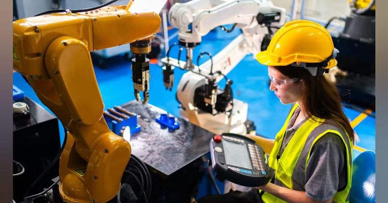
Over 50,000 hot-selling automation module components.

Reliable DCS Performance: Yokogawa Modules in Harsh Environments

Optimizing Yokogawa Processor Performance in Extreme Thermal Environments

The Critical Role of Thermal Resilience in Industrial Automation

Modern industrial automation demands hardware that survives beyond controlled control rooms. In sectors like oil and gas or chemical processing, ambient temperatures often fluctuate wildly. Yokogawa processor modules for CENTUM VP and legacy CS 3000 systems address these challenges directly. These controllers ensure continuous operation and safety in non-ideal environments. Consequently, engineers can place control cabinets closer to the process area. This proximity reduces signal wiring length and enhances overall response reliability.

Technical Deep Dive: Achieving Deterministic Control at 70°C

Yokogawa engineers these modules to withstand a rigorous range from -20°C to +70°C. This specification is more than a marketing figure; it represents industrial-grade component selection. Most standard PLCs suffer from thermal throttling, which causes scan jitter. However, Yokogawa maintains stable execution cycles even at peak heat. This stability ensures consistent PID performance and predictable interlock timing. Such precision is vital for pharmaceutical batch processes where timing deviations impact regulatory compliance.

Maximizing System Longevity Through Strategic Derating

At Powergear X Automation, we observe that Yokogawa utilizes conservative component derating. This design choice significantly slows the thermal aging of CPUs and power regulators. While the hardware supports 70°C, we recommend maintaining internal cabinet temperatures below 55°C. Lower temperatures exponentially improve the Mean Time Between Failures (MTBF). Furthermore, passive ventilation often proves more reliable than small air conditioners in dusty or corrosive environments.

Installation Best Practices for Harsh Field Conditions

Reliable factory automation requires more than just high-spec hardware. Proper installation remains the foundation of system uptime. Consider these technical requirements:

  • Stabilize cabinets above -10°C before performing a cold start.
  • Use locking terminal blocks to prevent vibration-induced loosening.
  • Avoid routing high-current cables near sensitive processor backplanes.
  • Implement grounding according to IEC 61000-5-2 standards.
  • Monitor mixed-generation nodes for thermal expansion issues.

Strategic Upgrading: From CS 3000 to CENTUM VP

Transitioning from legacy CS 3000 to CENTUM VP offers significant thermal advantages. Older modules are robust, but newer processors utilize advanced semiconductor processes. These modern components provide better heat dissipation and enhanced onboard diagnostics. If your facility regularly exceeds 60°C, upgrading is a proactive safety measure. Always verify firmware alignment when integrating new processors with older I/O modules to prevent communication errors.

Real-World Application Scenarios

  • Upstream Oil & Gas: Remote wellhead control in desert or arctic conditions.
  • Chemical Processing: Outdoor utility plants with high radiant heat signatures.
  • Offshore Platforms: Compact cabinets where dense I/O creates internal heat pockets.

Expert FAQ: Selection and Maintenance Insights

Q1: How do I choose between standard and wide-temperature rated modules for a new project?
Focus on the “Worst Case” internal cabinet temperature rather than the outside climate. If your cabinet lacks active cooling and houses high-density I/O, always opt for the extended range modules to prevent premature CPU aging.

Q2: Can I mix CENTUM VP processors with CS 3000 I/O in high-heat areas?
Yes, but exercise caution. While functionally compatible, older I/O modules often fail before the newer processors under thermal stress. We suggest auditing the heat tolerance of your oldest components before performing a partial upgrade.

Q3: What is the most common “hidden” failure cause in hot environments?
It is rarely the CPU itself. Instead, electrolytic capacitors in older power supply assemblies often dry out. If your system is over 10 years old, replace the power modules before pushing the system into high-temperature seasons.

Author’s Insight: Reliability in extreme temperatures is not just about survival; it is about maintaining predictable control for decades. For more technical guides and premium components, visit Powergear X Automation to optimize your control systems.

Is the 1769-L23E-QBFC1B Expandable? Expansion Cable Guide

Is the 1769-L23E-QBFC1B Expandable? Expansion Cable Guide

Understanding the 1769-L23E-QBFC1B: Limits of Expansion Cables and I/O Architecture

The Core Design of Integrated CompactLogix Systems

The 1769-L23E-QBFC1B stands as a cornerstone for small-scale industrial automation. Rockwell Automation designed this specific CompactLogix model to streamline engineering time. It merges the CPU, power supply, and diverse I/O points into a single, fixed housing. This “all-in-one” approach benefits machine builders who require a smaller cabinet footprint. However, users must understand the hardware’s structural boundaries before finalizing a system design.

Is the 1769-L23E-QBFC1B Expandable? Expansion Cable Guide

Can You Connect Additional 1769 Modules via Expansion Cables?

A frequent question in factory automation involves the use of 1769-CRR1 or 1769-CLL1 expansion cables with this unit. The answer is no. The 1769-L23E-QBFC1B features a fixed I/O architecture. It does not possess the right-side bus interface required to connect additional local 1769 modules. Therefore, you cannot physically extend the backplane to accommodate more digital or analog cards. This hardware limitation distinguishes the L23 series from more modular counterparts like the L30 or L33ER series.

Leveraging EtherNet/IP for System Scalability

Although local expansion is restricted, the integrated EtherNet/IP port offers a powerful alternative for growth. Engineers can scale their control systems by deploying distributed I/O blocks or remote adapters. According to MarketsandMarkets, the industrial Ethernet market continues to grow as plants move toward decentralized control. By using the ODVA-standard EtherNet/IP protocol, this controller manages networked drives and remote sensors efficiently. This method often proves more flexible than traditional ribbon-cable expansion in modern PLC environments.

Strategic Selection: Fixed vs. Modular Controllers

Choosing the right PLC involves balancing immediate costs against future flexibility. The 1769-L23E-QBFC1B excels in OEM equipment where the I/O count remains constant. For example, a standard labeling machine rarely needs more than the onboard high-speed counters and analog points. However, if your production line expects future upgrades, a modular controller is safer. In those cases, opting for a system that supports physical expansion cables prevents a total hardware rip-and-replace later.

Author Insights from PLCDCSHUB

At PLCDCSHUB, we often see commissioning delays caused by “expansion surprises.” Many technicians assume all 1769-labeled products share the same bus capabilities. We recommend always verifying the “Right-End Cap” compatibility before purchase. If your project demands high-speed deterministic execution across multiple racks, the L23 series might be too restrictive. For the best selection of genuine automation hardware and technical support, visit PLCDCSHUB Limited to explore compatible alternatives.

Installation and Maintenance Best Practices

  • Reserve Spare Capacity: Always leave at least 25% of the onboard I/O points open for emergency field changes.
  • Vibration Management: Use industrial-grade shielded Ethernet cables to prevent packet loss in high-vibration zones.
  • Firmware Alignment: Ensure your Studio 5000 or RSLogix 5000 version matches the controller’s major revision for stable communication.
  • Environmental Shielding: Keep the integrated unit away from high-heat sources to prolong the life of the internal power supply.

Application Scenario: Precision Packaging Control

In a typical high-speed cartoning application, the 1769-L23E-QBFC1B manages the primary logic and integrated motion. The onboard high-speed counter tracks the conveyor encoder, while analog outputs control motor speeds. Because the machine design is standardized, the lack of expansion cables is an advantage—it prevents unauthorized field modifications that could destabilize the original timing. If a secondary feeder is added later, a remote Point I/O module via Ethernet provides the necessary link.

Frequently Asked Questions (FAQ)

Q: What happens if I run out of I/O points on an L23E during commissioning?
Since you cannot add local modules, you must either use an Ethernet-based remote I/O block (like 1734-AENT) or replace the controller with a modular L3 series unit. We suggest checking PLCDCSHUB for immediate stock on remote adapters.

Q: Does the lack of expansion cables affect the controller’s processing speed?
No. The processing power is dedicated to the fixed I/O and communication tasks. In fact, fixed I/O often results in slightly faster update times (RPI) because the data doesn’t have to travel across an external bus cable.

Q: Can I use the 1769-L23E-QBFC1B as a gateway for other PLCs?
Yes. Its EtherNet/IP port supports messaging (MSG instructions), allowing it to act as a data concentrator between older SLC 5/05 systems and newer ControlLogix architectures, provided they are on the same network subnet.

For more technical deep-dives and to procure high-quality industrial modules, visit our official site at PLCDCSHUB Limited.

Bently Nevada 133819-01 vs 133811-02: Isolated I/O Comparison

Bently Nevada 133819-01 vs 133811-02: Solving Temperature Fluctuations in Machinery Protection

Reliable temperature monitoring is crucial for protecting critical rotating machinery from thermal stress. In heavy industrial environments, choosing the correct I/O module prevents catastrophic asset failures. The Bently Nevada 3500/60 temperature monitor relies heavily on these interfaces to deliver accurate data to the primary control systems. However, choosing between the isolated 133819-01 and the non-isolated 133811-02 drastically impacts data stability.

Understanding the Power of Galvanic Isolation in the 133819-01

The Bently Nevada 133819-01 features an isolated I/O architecture designed for harsh industrial automation environments. This module provides complete galvanic isolation between the field sensor wiring and the 3500 system backplane. Consequently, it blocks parasitic electrical noise from corrupting delicate thermocouple and RTD millivolt signals. At Powergear X Automation, our field experience shows that isolation acts as a definitive barrier against unpredictable common-mode voltages.

Why the Non-Isolated 133811-02 Triggers Signal Oscillations

The 133811-02 module lacks internal electrical isolation, making it vulnerable to external electromagnetic interference. Ground potential differences between the field device and the control cabinet create ground loops. These loops inject stray currents into the signal path, causing sudden temperature jumps of 5°C to 20°C. Therefore, users should deploy the 133811-02 only in pristine environments with unified grounding grids.

Mitigating Noise in DCS and PLC Integrated Networks

Modern factory automation heavily integrates temperature monitors with distributed control systems (DCS) and programmable logic controllers (PLC). When sensor cables run parallel to high-power motor feeders or variable frequency drives (VFDs), cross-talk occurs. Non-isolated modules register this electromagnetic interference as random data spikes. Upgrading to the isolated 133819-01 solves these issues without requiring expensive field cable replacements.

Installation Best Practices for Machinery Protection Systems

Engineers must follow precise installation guidelines to maintain signal integrity across critical plant assets:

  • Maintain Single-Point Grounding: Terminate cable shields at one end only to prevent ground loop formation.
  • Enforce Cable Separation: Route low-voltage instrument lines far away from high-current VFD output cables.
  • Deploy External Surge Protection: Install localized lightning surge arrestors for all outdoor sensor runs.

Implementing these steps drastically minimizes nuisance alarms and boosts overall machinery protection reliability.

Author Commentary: The Powergear X Automation Technical Perspective

In our view at Powergear X Automation, relying on non-isolated modules like the 133811-02 in modern facilities introduces unnecessary operational risks. Industrial plants now feature hundreds of switching power supplies and VFDs that saturate local ground grids with high-frequency harmonic noise. Investing upfront in the isolated 133819-01 module significantly reduces troubleshooting hours, prevents false trips, and protects long-term asset health.

If you are looking to upgrade your turbine or compressor monitoring system, you can browse high-quality hardware directly on Powergear X Automation to find reliable, industrial-grade monitoring components.

Real-World Solution Scenario: Resolving Nuisance Trips in a Petrochemical Plant

A major petrochemical processing facility experienced frequent, unexplained high-temperature alarms on a critical centrifugal compressor. The system utilized the non-isolated 133811-02 module connected to 80-meter thermocouple runs. Investigations revealed that the temperature spikes synchronized perfectly with the startup cycle of a nearby 500kW cooling tower motor. The engineering team replaced the interface with the isolated Bently Nevada 133819-01 module. Instantly, the signal variance dropped from ±12°C to a stable ±0.3°C, completely eliminating the costly production shutdowns.

Frequently Asked Questions

Q1: Can I use the 133819-01 as a direct drop-in replacement for the 133811-02?
Yes, functionally they both interface with the 3500/60 monitor card. However, you must verify your specific firmware compatibility version before upgrading.

Q2: What is the maximum recommended cable distance for the non-isolated 133811-02?
We recommend limiting non-isolated sensor cable runs to under 50 meters in low-noise environments to avoid data degradation.

Q3: How do ground loops specifically affect thermocouple readings?
Ground loops create small stray voltages that add to or subtract from the thermocouple’s millivolt output, generating false temperature shifts.

Allen-Bradley 1769-L33ER vs 1769-BA PLC Reliability Guide

Allen-Bradley 1769-L33ER vs 1769-BA: PLC Reliability Guide

Optimizing Industrial Uptime: From 1769-BA Batteries to 1769-L33ER Controllers

The Critical Role of Power Backup in Legacy Control Systems

In traditional factory automation, the 1769-BA battery serves as a vital safeguard for legacy CompactLogix controllers. This lithium cell maintains volatile RAM during power interruptions. Without a functional battery, a controller loses its entire user program and tag data. Consequently, unplanned outages often result in extensive recovery times. Maintenance teams must then manually re-download code via Studio 5000. This vulnerability creates a significant risk for continuous processes like chemical manufacturing or pharmaceutical production.

Allen-Bradley 1769-L33ER vs 1769-BA PLC Reliability Guide

Allen-Bradley 1769-L33ER vs 1769-BA PLC Reliability Guide

Transitioning to Battery-Free Reliability with 1769-L33ER

Modern engineering standards prioritize hardware that eliminates single points of failure. The 1769-L33ER represents a major technological leap in the Allen-Bradley CompactLogix family. Unlike its predecessors, this controller utilizes non-volatile flash memory to store logic. It effectively removes the dependency on the 1769-BA battery for data retention. As a result, the system remains robust during extended power losses. This architecture is particularly beneficial for remote oil and gas assets where routine maintenance is difficult.

Technical Comparison: Volatile RAM vs. Non-Volatile Flash

Understanding the underlying memory mechanics is essential for system selection. Older L3x series controllers rely on battery-backed SRAM. If the 1769-BA fails while power is off, the RAM clears instantly. However, the 1769-L33ER writes data to internal flash memory. This design ensures the program survives indefinitely without external power. Furthermore, the L33ER supports dual Ethernet/IP ports for DLR (Device Level Ring) topologies. This integration improves both data security and network resilience compared to older serial-based units.

Impact of Environmental Factors on Battery Longevity

Field data suggests that ambient temperature dictates the lifespan of industrial batteries. A standard 1769-BA typically lasts about five years under ideal conditions. Nevertheless, high-heat environments like steel mills can reduce this by 50%. Frequent power cycling also accelerates the depletion of the lithium cell. Automation managers should implement predictive replacement schedules to avoid CPU faults. Alternatively, upgrading to battery-free controllers like the 1769-L33ER simplifies the long-term maintenance of the control cabinet.

Best Practices for Installation and Migration

  • Live Replacement: Always swap 1769-BA batteries while the PLC power is on to protect memory.
  • Firmware Verification: Ensure your Studio 5000 version supports the L33ER hardware profile before migration.
  • Code Documentation: Maintain a current .ACD backup file regardless of your memory type.
  • SOP Updates: Remove battery inspection steps from your PM checklists after installing L33ER units.
  • Thermal Control: Keep control panels below 40°C to protect sensitive electronic components.

B2B Solution Scenarios

  • Remote Pump Stations: Use the 1769-L33ER to ensure the station reboots instantly after a power failure without technician intervention.
  • High-Speed Packaging: Deploy L33ER controllers to utilize integrated Motion over Ethernet/IP for better synchronization.
  • Legacy Plant Refresh: Replace aging L32E units with L33ER controllers to eliminate the 1769-BA replacement cycle.

Expert FAQ

Q: Can I use a 1769-BA battery in a 1769-L33ER controller?
A: No, the L33ER does not have a battery slot. It uses an internal capacitor and flash memory for data retention.

Q: What happens if my L32E battery light turns red?
A: This indicates a low voltage state. You must replace the battery immediately while power is applied to avoid losing the program.

Q: Is the 1769-L33ER compatible with my existing 1769 I/O modules?
A: Yes, it supports the standard 1769 Compact I/O bus, making it an excellent drop-in replacement for older systems.

Bently Nevada 176449 Rear IO Module Selection Guide_

3500 System Machinery Protection: 176449 I/O Modules

Decoding Bently Nevada 176449 Series Rear I/O Modules for 3500 Machinery Protection Systems

In high-stakes industrial automation, continuous condition monitoring safeguards multimillion-dollar rotating assets. The Bently Nevada 3500 system relies heavily on specialized backplane connectivity to process field sensor data. Specifically, the 176449 series Rear I/O modules provide critical electrical termination and signal routing. Choosing the wrong dash-number option can compromise your entire machinery protection strategy. This comprehensive guide breaks down the variations, technical principles, and installation rules for these critical components.

Bently Nevada 176449 Rear IO Module Selection Guide_

Bently Nevada 176449 Rear IO Module Selection Guide_

The Functional Architecture of 176449 Rear Interface Boards

The 176449 family acts as the physical interface between field-mounted transducers and front-end monitor cards. Each module routes raw analog voltages from proximity probes, accelerometers, or pressure sensors safely into the rack. Moreover, the internal circuitry isolates delicate processing microprocessors from unpredictable field surges. This isolation maintains signal stability in noisy environments near massive turbomachinery. Therefore, these rear boards form the foundation of any reliable API 670 protection loop.

Understanding Core Model Variances and Monitor Pairings

Rear I/O Part NumberAssociated Monitor CardPrimary Target Application
176449-013500/40M ProximitorShaft vibration and dynamic radial position monitoring
176449-023500/42M Proximitor/SeismicCombined velocity, acceleration, and case expansion tracking
176449-043500/45 PositionThrust position, differential expansion, and valve metrics
176449-073500/77M Recip PressureReal-time reciprocating compressor cylinder diagnostics

Signal Conditioning and Channel Topology Principles

Each variations within the 176449 family utilizes distinct input resistance paths and grounding layouts. For instance, the 176449-01 matches the negative voltage modulation typical of eddy-current proximity probes. In contrast, the 176449-07 handles rapid transient pressure spikes inside combustion or compression chambers. Consequently, mixing these cards up causes severe scaling errors or complete signal dropouts. The front processor card simply cannot normalize a signal conditioned by an incompatible rear board.

The API 670 Standard and System Interlocking Integrity

In power generation and petrochemical refining, machinery protection systems operate under strict API 670 compliance rules. This standard mandates that component failures must not prevent an emergency trip from executing properly. A degraded terminal block or a loose jumper on the Rear I/O card can mask dangerous shaft deflections. As a result, the DCS might receive faulty baseline data, delaying automated shutdown procedures. Proactive maintenance teams always treat rear hardware with the same care as front-facing processing modules.

Best Practices for Field Commissioning and Maintenance

  • Verification First: Double-check the precise dash-number configurations before sliding any module into the rack chassis.
  • ⚙️ Torque Optimization: Secure terminal strip screws tightly to eliminate intermittent signal noise caused by cabinet vibration.
  • 🔧 Shield Management: Drain cable shields strictly according to the Bently Nevada manual to prevent dangerous grounding loops.

Strategic Sourcing Commentary from Powergear X Automation Limited

At Powergear X Automation Limited, we observe widespread issues stemming from the use of unchecked surplus parts. Many plants buy replacement modules from unverified brokers without cross-referencing their specific revision histories. A physical board might fit perfectly into a 3500 slot while remaining electronically incompatible with your sensor software setup. We recommend auditing your entire spare parts inventory every year to ensure exact compatibility. For certified, high-performance machinery protection hardware, explore our validated listings at https://www.powergearx.com/.

Real-World Deployment and Solutions

During a recent gas terminal overhaul, engineers faced recurring channel errors on a critical centrifugal compressor. While the 3500/42M monitor tested perfectly on the bench, it threw persistent faults when installed in the rack. The troubleshooting team eventually tracked the issue to an old 176449-02 board suffering from micro-fractures along its backplane connector pins. Replacing the worn rear module instantly restored full diagnostic visibility, preventing an expensive forced outage during plant startup.

Frequently Asked Questions (FAQ)

1. Why does my 3500 software report a configuration mismatch when the front monitor matches the sensor?
This error usually indicates that the installed rear terminal module does not match the channel profile expected by the monitor. The 3500 rack verifies the ID of both the front and rear modules before allowing communication to initialize.

2. Can I use a 176449-02 card to pull dynamic signals into a standalone diagnostic data collector?
Yes. The 176449-02 provides buffered output terminals on the rear face for easy analyzer connection. This configuration allows technicians to connect diagnostic instruments without disturbing active safety trip loops.

3. What environmental factors cause the highest rate of failure on these specific rear cards?
Corrosive gas exposure, particularly hydrogen sulfide (H2S) in refinery settings, accelerates the oxidation of the exposed terminal contacts. Always ensure your marshalling enclosures maintain positive pressure and active chemical air filtering.

Preventing Industrial EMI CC-TDI110 Installation Best Practices_

Preventing Industrial EMI: CC-TDI110 Installation Best Practices

Maximizing Signal Reliability with the Honeywell CC-TDI110 Digital Input Module

The Core Role of Digital Inputs in DCS Reliability

Modern industrial automation relies on precise data acquisition from field devices to the Distributed Control System (DCS). The Honeywell CC-TDI110 Digital Input Module serves as a critical bridge in this communication chain. Specifically, it excels in high-power environments like petrochemical plants and heavy manufacturing lines. Maintaining signal integrity is paramount in these settings. Consequently, engineers must prioritize proper shielding to prevent costly false trips or missed alarms.

Preventing Industrial EMI CC-TDI110 Installation Best Practices_

Preventing Industrial EMI CC-TDI110 Installation Best Practices_

Enhancing Isolation Against Electromagnetic Interference

The CC-TDI110 features robust channel-to-channel and channel-to-ground isolation. This design allows the module to detect digital states accurately despite nearby high-voltage cables. However, isolation alone cannot solve all noise problems. Electrical noise often originates from poor cable routing rather than internal component failure. Therefore, system integrators should treat internal isolation as a secondary defense rather than a primary solution.

Managing Common-Mode Noise in VFD Environments

Industrial facilities frequently utilize large motors and Variable Frequency Drives (VFDs). These devices generate significant Common-Mode Interference that can overwhelm standard control systems. The CC-TDI110 offers a high tolerance to this noise, ensuring stable performance. Nevertheless, if signal cables sit too close to power lines, induced voltages might exceed these rejection thresholds. Reliable factory automation requires a strict physical separation between signal and power conductors.

Advanced Input Filtering and Debounce Mechanisms

Transient noise can trigger nuisance alarms if a module lacks proper filtering. The CC-TDI110 addresses this through configurable debounce times that suppress short-lived electrical spikes. While these filters improve stability, they are not a cure for chronic interference. Excessive noise persisting beyond the filter window can still cause unintended shutdowns. As a result, Powergear X Automation recommends validating filter settings during the commissioning phase.

Best Practices for Shielded Cable Installation

Proper installation is the foundation of long-term system stability. When routing signals near motor feeders or lines exceeding 220V AC, always use shielded twisted-pair cables. Maintain at least 300 mm of clearance according to IEC 61000-5-2 guidelines. Furthermore, ensure any unavoidable crossings occur at a 90-degree angle. This technique effectively minimizes inductive coupling and preserves the purity of the digital signal.

Critical Shield Grounding and Segregation Strategies

A frequent mistake in the field involves grounding cable shields at both ends. This creates ground loops that introduce more noise into the system. For the CC-TDI110, engineers should ground the shield only at the DCS cabinet. Additionally, never share cable trays between high-current power lines and sensitive signal wires. We have observed cases where segregating cables into dedicated metallic trays instantly resolved intermittent DI flickering.

Strategic Insights from Powergear X Automation

In our experience at Powergear X Automation, hardware quality is only half the battle. The CC-TDI110 is a world-class module, but its performance depends on the surrounding infrastructure. We recommend a “holistic shielding” approach that combines high-quality Honeywell hardware with strict adherence to IEC standards. Investing in proper wiring today prevents expensive downtime in the future.

Technical Summary Checklist

  • Use shielded twisted-pair cables for all digital inputs.
  • Ground shields at the DCS side only to prevent loops.
  • Maintain 300 mm separation from high-power cables.
  • Configure debounce times to match field device characteristics.
  • Install Surge Protection Devices (SPD) in lightning-prone areas.

Practical Application Scenarios

  • Refinery Safety Interlocks: Ensuring emergency shutdown valves report status without EMI-induced false positives.
  • Power Plant Turbine Control: Monitoring high-speed digital states near heavy electrical switching equipment.
  • Chemical Batch Processing: Maintaining accurate sequence control where VFDs are used extensively for agitation.

Expert FAQ: CC-TDI110 Implementation

Q1: How do I choose between the CC-TDI110 and legacy Honeywell DI modules?
Evaluate your current electromagnetic environment first. While the CC-TDI110 is often backward compatible, it offers superior noise rejection features necessary for modern VFD-heavy plants. If your facility has upgraded its power hardware, upgrading your I/O modules is a wise technical move.

Q2: What is the most common cause of “flickering” signals in new installations?
Usually, it is a grounding issue. Ensure your shields are not creating loops and check for 90-degree crossings at power intersections. If the issue persists, increase the software debounce time slightly within the DCS configuration.

Q3: Does this module require specialized maintenance during its lifecycle?
The CC-TDI110 is largely maintenance-free. However, we recommend annual inspections of the terminal blocks and grounding bars. Loose connections are a silent killer of signal integrity in high-vibration industrial settings.

1769-L24ER-QB1B vs 1769-L23E: Upgrade Guide | PLCDCS HUB

1769-L24ER-QB1B vs 1769-L23E: Upgrade Guide | PLCDCS HUB

1769-L24ER-QB1B vs 1769-L23E: Essential Migration Guide for Industrial Automation

The Evolution of CompactLogix Control Systems

The 1769-L24ER-QB1B represents a significant leap in factory automation compared to the legacy 1769-L23E. This modern controller delivers enhanced processing power and integrated motion capabilities. It specifically addresses the networking bottlenecks found in older hardware. However, transitioning between these two units requires a strategic engineering approach rather than a simple swap.

1769-L24ER-QB1B vs 1769-L23E: Upgrade Guide | PLCDCS HUB

Processing Power and Memory Advancements

The L24ER-QB1B offers superior user memory and execution speeds for complex control systems. These improvements directly impact high-speed applications like automated packaging or precision bottling.

  • Faster scan times significantly reduce command latency.
  • Expanded memory supports advanced data logging and complex logic.
  • Improved task multitasking prevents processor overloads during peak cycles.
  • PLCDCS HUB observes that faster execution may require recalibrating legacy timers.

Revolutionizing Connectivity with Dual Ethernet Ports

Unlike the single-port 1769-L23E, the L24ER-QB1B features dual Ethernet/IP ports with an embedded switch. This architecture is vital for modern industrial automation environments requiring high uptime.

  • Supports Device Level Ring (DLR) topologies for network resiliency.
  • Eliminates the need for expensive external managed switches.
  • Simplifies wiring within the control cabinet.
  • Reduces hardware failure points in continuous processing plants.

Integrated Motion Control via Ethernet/IP

One primary advantage of the L24ER-QB1B is its ability to handle integrated motion. This feature allows engineers to manage servo drives directly through the controller.

  • Reduces system complexity by removing dedicated motion modules.
  • Enhances synchronization between multiple axes of movement.
  • Minimizes mechanical wear through smoother motion profiles.
  • Lowers the total cost of ownership for specialized machinery.

Critical Installation and Software Requirements

Upgrading to the L24ER-QB1B involves shifting from RSLogix 5000 to Studio 5000 Logix Designer. This software transition is mandatory for accessing the latest firmware features.

  • Always verify firmware compatibility before attempting a project download.
  • Maintain proper physical spacing to ensure optimal heat dissipation.
  • Utilize shielded cabling to protect integrated I/O from EMI.
  • Check grounding points to prevent unexpected signal noise interference.

Expert Analysis from PLCDCS HUB

At PLCDCS HUB, we see the 1769-L24ER-QB1B as a cornerstone for digital transformation. While the initial investment is higher, the long-term reliability justifies the cost. Legacy systems often struggle with modern security protocols that this controller handles with ease. We recommend this upgrade for any facility aiming for PLC-based network redundancy.

Application Scenarios and Solutions

  • High-Speed Packaging: Utilizing DLR for zero-downtime communication between stations.
  • Pharmaceutical Production: Leveraging increased memory for strict 21 CFR Part 11 data tracking.
  • Food and Beverage: Implementing integrated motion for precise filling and capping operations.

Technical Implementation Checklist

  • ✅ Verify that your existing I/O mapping matches the QB1B integrated points.
  • ✅ Ensure all network nodes support the chosen Ethernet topology.
  • ✅ Confirm Studio 5000 version alignment with the hardware revision.
  • ✅ Audit the power supply capacity for the updated controller load.

Frequently Asked Questions

How do I handle I/O differences during a hardware migration?
The L24ER-QB1B features integrated I/O which differs from the modular L23E layout. You must rewrite the I/O configuration in Studio 5000 and update physical wiring diagrams.

What is the most common pitfall when upgrading these controllers?
The most common issue involves faster logic execution affecting old “one-shot” instructions. Always perform a dry run to ensure the faster scan time doesn’t break logic.

Is it better to repair an old L23E or buy the L24ER-QB1B?
If you need motion control or network redundancy, buy the L24ER-QB1B. For simple, isolated machines with no growth plans, a repair might suffice temporarily.

Explore our extensive inventory of high-performance controllers at PLCDCS HUB Limited to find the right solution for your facility.

Honeywell CC-PWRN01 Guide Thermal Management in DCS Cabinets

Honeywell CC-PWRN01 Guide: Thermal Management in DCS Cabinets

Ensuring DCS Stability: Thermal Management for the Honeywell CC-PWRN01 Power Module

The Critical Role of Reliable Power in Industrial Automation

The Honeywell CC-PWRN01 power module provides essential redundant energy to modern Distributed Control Systems (DCS). It secures continuous operations in demanding sectors like oil, gas, and pharmaceutical production. However, system reliability depends heavily on proper thermal management. Overheating remains a leading cause of premature component failure in industrial environments. Therefore, engineers must prioritize vertical installation spacing to maintain long-term system health.

Honeywell CC-PWRN01 Guide Thermal Management in DCS Cabinets

Honeywell CC-PWRN01 Guide Thermal Management in DCS Cabinets

Optimizing Vertical Spacing for Natural Convection

For the CC-PWRN01, maintaining a vertical clearance of 50–75 mm is vital for air circulation. Natural convection moves heat from the bottom to the top of the cabinet. If you obstruct this flow, internal temperatures may exceed the +70°C design limit. Moreover, restricted airflow significantly shortens the lifespan of sensitive electrolytic capacitors. In our experience, tight spacing creates hot spots that sit 15°C above the ambient cabinet temperature.

Managing Load Capacity to Reduce Heat Generation

Power modules generate substantially more heat when operating at peak capacity. Continuous high-load conditions accelerate the aging process of internal electronics. As a result, the risk of cascading failures in redundant configurations increases. At Powergear X Automation, we suggest designing systems for 60–70% of the nominal load. This conservative approach provides a safety buffer during seasonal temperature spikes or ventilation issues.

Adapting Cabinet Ventilation for Harsh Climates

The CC-PWRN01 typically relies on passive cooling within the control cabinet. Sealed or high-IP-rated enclosures require even larger spacing to prevent heat accumulation. In regions like the Middle East or Southeast Asia, ambient heat demands stricter standards. We frequently increase vertical spacing to ≥80 mm for these high-temperature projects. Furthermore, integrating heat exchangers or fan trays becomes mandatory when passive cooling reaches its physical limits.

Installation Best Practices for Power Modules

Proper physical placement ensures that heat does not affect other critical system components. Engineers should always stack power modules vertically to align with natural airflow. Additionally, avoid placing sensitive controllers or I/O processors directly above a heat-generating power supply. We once resolved recurring communication faults in a refinery by simply relocating a controller away from a module’s heat path. These small adjustments prevent significant thermal stress on the entire DCS architecture.

Routine Maintenance and Thermal Inspection Strategies

Regular inspections keep your factory automation system running at peak efficiency. Use infrared thermometers to measure the surface temperature of the CC-PWRN01 during operation. If surface readings exceed 65°C, you must immediately investigate airflow obstructions or spacing issues. Moreover, dust accumulation can reduce heat dissipation efficiency by up to 20%. Therefore, cleaning internal components during scheduled shutdowns is a simple yet effective reliability strategy.

Professional Insights from Powergear X Automation

At Powergear X Automation, we believe that thermal design is as important as electrical wiring. Modern power modules like the CC-PWRN01 are highly efficient, but they still follow the laws of thermodynamics. Neglecting a few centimeters of space can lead to millions in lost production due to an unexpected trip. We recommend a comprehensive thermal audit for every cabinet upgrade to ensure modern hardware performs within its optimal environment.

Technical Installation Checklist

  • Maintain a minimum of 50–75 mm vertical clearance between units.
  • Mount modules vertically to support natural bottom-to-top airflow.
  • Use perforated cable ducts to avoid trapping heat near the module.
  • Avoid tight cable bundling directly above the power supply vents.
  • Verify that the total load stays under 75% for unventilated cabinets.

Industrial Application Scenarios

  • Offshore Platforms: Maintaining redundant power in compact, high-ambient-temperature control rooms.
  • Chemical Processing: Preventing thermal-induced shutdowns in sealed cabinets protected from corrosive gases.
  • Pharmaceutical Batching: Ensuring high-availability power for critical sequence controllers during long production cycles.

Expert FAQ: CC-PWRN01 Implementation

Q1: How do I verify if my current cabinet spacing is sufficient?
If your vertical spacing is ≥50 mm and the cabinet interior stays below 40°C under full load, your setup is generally safe. However, if you notice the module shell feels excessively hot to the touch, consider increasing the gap to 80 mm or adding an exhaust fan to the cabinet roof.

Q2: Can I replace legacy Honeywell power supplies with the CC-PWRN01 directly?
While they are often mechanically compatible, never skip a thermal audit. Newer modules might have higher power densities and different heat profiles than 20-year-old units. Ensure the existing cabinet layout can handle the heat dissipation of the new module before finalizing the retrofit.

Q3: What are the signs of a power module failing due to heat?
Look for discolored plastic housing, bulging capacitors visible through the vents, or frequent “redundancy lost” alarms. If you detect a sweet or burnt smell during a cabinet inspection, the module is likely overheating and requires immediate replacement to avoid a total system failure.

For more technical guides and high-quality automation components, visit Powergear X Automation today.

Honeywell CC-TAIX51 Guide: Solving Humidity-Induced Packet Loss

Reducing Packet Loss in Honeywell CC-TAIX51 Analog Input Modules

The Importance of Precision in Critical Process Industries

The Honeywell CC-TAIX51 analog input module provides high-precision signal acquisition for complex Distributed Control Systems (DCS). It serves vital sectors like oil & gas, pharmaceuticals, and chemical processing. However, high-humidity environments often trigger unexpected communication packet loss. This issue undermines system reliability and causes delayed control responses. Understanding these environmental triggers helps engineers prevent intermittent faults and maintain continuous production cycles.

How Micro-Condensation Disrupts Factory Automation Hardware

Standard industrial ratings often cover humidity levels up to 95% non-condensing. Nevertheless, rapid temperature shifts inside control cabinets create micro-condensation on PCB surfaces. Moisture forms conductive paths between sensitive communication traces. Consequently, this leads to signal distortion or transient short circuits. In fast PID control loops, even minor data acquisition delays can destabilize the entire process.

Maintaining Signal Integrity and Isolation Barriers

The CC-TAIX51 relies on high-impedance circuits to ensure accurate analog data. Humid conditions increase leakage current across these critical isolation barriers. As a result, insulation resistance drops and the signal-to-noise ratio (SNR) weakens. While analog values might only fluctuate slightly, the internal I/O link often suffers. This manifests as checksum failures and data retransmissions at the controller level.

Protecting High-Speed Backplane Communication Stability

These modules communicate with the DCS controller via high-speed backplane interfaces. Humidity and airborne contaminants quickly oxidize these metal connectors. Increased contact resistance introduces timing jitter or bit errors during data transfer. Therefore, communication drops occur more frequently under high system loads. Regular hardware inspection remains the best defense against these physical layer failures.

Optimizing Control Cabinet Climate Management

Field experience shows that climate control is more effective than simple sealing. We recommend installing anti-condensation heaters inside every critical cabinet. Technicians should maintain the internal temperature at least 5°C above the ambient dew point. Sealed IP-rated enclosures without thermal regulation often trap moisture inside. Proper airflow management ensures long-term reliability for all factory automation components.

Implementing Conformal Coating and Connector Care

For offshore or coastal installations, factory-applied conformal coating provides essential protection. Ensure all coatings comply with the IEC 61086 standard for industrial electronics. During maintenance shutdowns, use non-residue contact cleaners on backplane connectors. Re-seating modules restores proper contact pressure and clears oxidation. Powergear X Automation observers suggest that many “failed” modules only require professional cleaning to resume service.

Expert Analysis from Powergear X Automation

At Powergear X Automation, we believe environmental management defines hardware lifespan. The CC-TAIX51 is a robust component, but it cannot overcome poor cabinet design. Engineers should prioritize proactive thermal monitoring over reactive module replacement. Combining high-quality Honeywell hardware with rigorous maintenance standards significantly reduces total cost of ownership. Visit our website for more technical solutions and high-reliability automation hardware.

Technical Maintenance Checklist

  • 🔧 Install internal heaters to prevent micro-condensation.
  • 🔧 Maintain temperature 5°C above the local dew point.
  • 🔧 Use gold-plated or sealed connectors in high-corrosion zones.
  • 🔧 Verify firmware compatibility before swapping legacy modules.
  • 🔧 Schedule annual connector cleaning with non-residue agents.

Solution Scenario: Coastal Refinery Deployment

  • The Challenge: Intermittent “I/O Link Failure” alarms during morning temperature shifts.
  • The Discovery: Micro-condensation on the backplane due to high ambient salt-mist humidity.
  • The Fix: Installed regulated heaters and switched to conformal-coated CC-TAIX51 units.
  • The Result: Communication packet loss dropped to zero within the first 30 days.

Frequently Asked Questions

Q1: Why does my DCS report packet loss when the module seems powered on?
Communication requires much higher signal purity than simple power delivery. Humidity increases contact resistance, causing “bit-flip” errors that the DCS rejects as invalid packets. Powergear X recommends checking the backplane pins for discoloration first.

Q2: Is it better to replace an old module or improve cabinet cooling?
If the environment exceeds 95% humidity, a new module will eventually fail too. Improve the cabinet climate control first. However, if the old module shows visible corrosion on the gold fingers, replacement is necessary to prevent damaging the backplane.

Q3: How do I verify if my CC-TAIX51 is compatible with a legacy rack?
Always check the Honeywell hardware compatibility matrix for your specific firmware revision. Older racks may lack the modern shielding required for high-speed digital communication. In humid plants, consider upgrading the I/O base along with the module.

GE IS200JPDHG1A Troubleshooting: False Total Failure Alarms

Can Monitoring Circuit Drift on the GE IS200JPDHG1A Cause False System Trips?

In high-availability industrial automation, faulty diagnostic feedback can prove as damaging as actual physical hardware failures. The GE IS200JPDHG1A Power Distribution Board serves as the central power backbone within EX2100 excitation systems. Beyond distributing vital DC voltage rails, this board actively monitors subsystem health metrics. However, an isolated internal failure within its internal sensing loop can trick the main controller. Consequently, the DCS may generate an unwarranted “Power System Total Failure” critical alarm message.

The Functional Architecture of Power Supervision Circuitry

The IS200JPDHG1A integrates an intricate network of analog voltage dividers, operational amplifiers, and status signal comparators. These components constantly read feedback parameters across multiple incoming power feeds. After processing, the hardware forwards real-time status packets straight to the core turbine control systems. This architecture ensures that the controller can instantly identify sagging power lines. Therefore, the processing brain can protect downstream electronics before an absolute brownout disrupts plant operations.

How Internal Board Anomalies Generate Ghost Alarms

Component degradation can mimic a severe electrical blackout within the power distribution array. Over time, analog sensing channels can experience thermal resistance drift or comparator latch-up malfunctions. When this occurs, the diagnostic circuitry reports low or absent voltage despite a perfectly healthy DC bus. If the system lacks redundant cross-checking paths, a single sensor failure may trigger an immediate emergency trip. This false alarm unnecessarily isolates the entire generator excitation unit from the power grid.

Industry research indicates that up to 30% of power supply diagnostic alarms stem from feedback path errors. Pin oxidation on heavy backplane connectors can similarly attenuate the weak low-voltage telemetry signals. Moreover, old firmware configurations may misinterpret a single channel fault as an absolute power failure. Engineers must cross-reference actual physical bus bars before approving extensive control system module swaps.

Noise Immunity Vulnerabilities in Heavy Factory Automation

Turbine rooms host heavy electromagnetic fields generated by excitation transformers and massive variable frequency drives. The low-voltage supervisory lines on the IS200JPDHG1A remain susceptible to high-frequency induced noise. If cabinet grounding terminals loosen, common-mode noise can override the true analog feedback measurements. This electrical interference distorts waveform edges, leading to intermittent channel mismatch errors. Maintaining excellent shield continuity remains mandatory to protect signal tracking accuracy.

Evaluating Backward Compatibility and Selection Differences

Replacing an older power supervisor requires careful checking of part number suffix variations. While the base IS200JPDHG1A model handles standard distribution tasks, physical revision layers alter connector arrangements. Certain sub-versions feature specialized trace impedances designed to handle modern high-speed noise filtering tasks. Attempting to install an unverified board revision can introduce unintended parameter reading offsets. To avoid project delays, procure components from certified distributors like Powergear X Automation Limited.

Step-by-Step Diagnostic Verification Protocols

  • Physical Bus Measurement: Measure the true incoming DC control voltage directly using a calibrated digital multimeter.
  • ⚙️ Connector Inspection: Unplug and re-seat all communication cables while checking for immediate thermal pin discoloration.
  • 🔧 Chronological Log Analysis: Examine the ToolboxST event sequence to trace if channel faults preceded the total blackout alarm.

Strategic Maintenance Perspectives from Powergear X Automation Limited

At Powergear X Automation Limited, we emphasize that automatic hardware swapping often increases overall troubleshooting costs. When a total power failure indicator arises, blindly replacing the distribution block skips root-cause verification. Many issues resolve after cleaning oxidized edge contacts with manufacturer-approved chemical solvents. We suggest tracking sensing calibration trends during standard annual system turnarounds. To explore our comprehensive database of genuine GE components, visit our store at https://www.powergearx.com/.

Real-World Application Scenarios

During a baseline commissioning phase at a combined-cycle power station, operators reported a sudden, unexplained total power alarm. Physical tests confirmed that the main 125VDC auxiliary battery supply remained fully energized. Further analysis traced the error to an open-circuit feedback trace on the distribution board. Replacing the damaged module restored correct telemetry reporting, allowing the plant to achieve full production output without further delay.

Frequently Asked Questions (FAQ)

1. Why does a minor analog drift escalate to a complete total power system shutdown message?
If the controller code uses an unweighted “AND” condition across sensing channels, a single dead input simulates a total voltage loss. Updating your I/O block parameters to utilize voting logic solves this vulnerability.

2. Can I test the internal comparator circuitry of this board while the system runs online?
Online manual circuit tracing is highly discouraged due to short-circuit risks near the main power buses. Confine deep component-level validation to a static test bench during standard outage schedules.

3. How do I differentiate between a real input supply failure and a board-level telemetry fault?
A genuine supply failure simultaneously alters parallel monitoring systems, such as your main upstream switchgear breakers. If only the specific board reports zero volts while other metrics remain unchanged, suspect a telemetry issue.

Back to Top
Product has been added to your cart