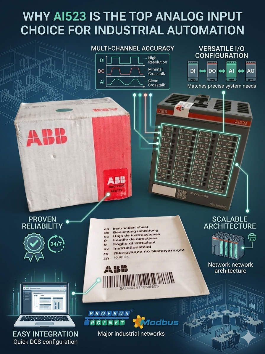
Why AI523 is the Top Analog Input Choice for Industrial Automation
Is the AI523 the Most Versatile Analog Module in the AC500 Series?
In many industrial automation projects, the analog I/O layer often becomes a hidden bottleneck. Signal instability and poor channel isolation can cause significant delays during commissioning. The ABB AI523 analog input module addresses these practical integration challenges effectively. It eliminates the need for complex external signal conditioning hardware. Consequently, process industries such as chemical plants and water treatment facilities prioritize this module for its reliability and flexibility.
 Why AI523 is the Top Analog Input Choice for Industrial Automation
Multi-Signal Compatibility in Modern Control Systems
The AI523 stands out because it supports multiple industrial signal standards simultaneously. It handles both current and voltage-based instrumentation within a single architecture. In retrofit projects, this flexibility proves invaluable. Engineers often encounter mixed field devices, ranging from legacy 0–10 V sensors to modern 4–20 mA transmitters. Using the AI523 reduces the need for additional converters. Therefore, it simplifies cabinet design and minimizes potential failure points.
Signal Stability and Noise Immunity Technical Principles
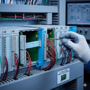
Analog signal quality directly impacts the stability of any DCS or PLC system. In motor-heavy environments, electromagnetic interference often triggers false alarms. The AI523 utilizes advanced filtering and channel isolation to improve long-term reliability. This technical design is crucial when Variable Frequency Drives (VFDs) operate near I/O cabinets. Stable acquisition prevents PID oscillation and ensures accurate batch dosing. As a result, operators avoid chasing “ghost” faults caused by electrical noise.
Environmental Reliability for Factory Automation
Industrial environments subject hardware to heat, vibration, and humidity. The AI523 features a robust terminal structure designed for long operational cycles. Loose wiring often causes intermittent signal loss in high-vibration areas like compressor stations. This module provides secure connections that reduce unplanned maintenance. Furthermore, its thermal management allows for dense cabinet installations without compromising performance. Investing in durable hardware lowers the total cost of ownership over the plant’s lifecycle.
Strategic Maintenance and Installation Guidelines
- ✅ Shielding Protocols: Ground analog cable shielding at one side only to prevent ground loops.
- ⚙️ Mechanical Integrity: Use ferrules on stranded conductors to ensure maximum terminal contact.
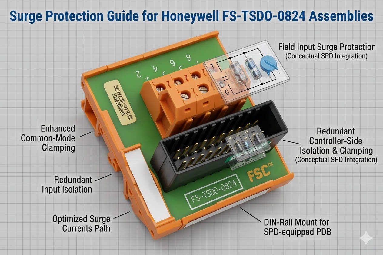
- 🔧 Surge Protection: Install dedicated surge protectors for any analog loops connected to outdoor instrumentation.
Authoritative Insight from Powergear X Automation Limited
At Powergear X Automation Limited, we believe that standardization is key to operational excellence. Standardizing on a universal module like the AI523 simplifies spare parts inventory. It also shortens the learning curve for maintenance technicians. We often see projects where inferior modules lead to hidden costs through intermittent downtime. Choosing the right interface is a strategic decision for any factory automation project. For a comprehensive range of ABB AC500 components, please visit our website at https://www.powergearx.com/.
Application Case: Pharmaceutical Process Skids
A recent pharmaceutical project required precise pressure and temperature monitoring across several skids. The engineers used the AI523 to integrate both legacy PT100 sensors and new HART-enabled transmitters. This approach allowed for a phased migration without halting production. The high-resolution acquisition ensured batch consistency and met strict regulatory standards. This case highlights how versatile I/O modules bridge the gap between different technology generations.
Frequently Asked Questions (FAQ)
1. How does the AI523 handle mixed active and passive current loops?
The module is adaptable, but you must plan your wiring carefully. We recommend verifying the power source for each loop. Proper distribution planning prevents overcurrent issues on the module’s backplane.
2. Can the AI523 be used in high-altitude energy facilities?
Yes, the AC500 series generally supports extended environmental ratings. However, check the derating curves for temperature and voltage isolation if your facility is above 2,000 meters.
3. What is the most common cause of “Input Overflow” errors on this module?
Overflow errors typically stem from a broken shield or an ungrounded signal reference. This causes common-mode voltage to drift beyond the module’s detectable range, even if the actual signal is correct.