Over 50,000 hot-selling automation module components.

Fix ABB PM861 Reboot: SD834 Power Ripple Diagnosis Guide

Diagnosing ABB PM861 reboots: How to detect aging capacitors in SD834 power supplies online

In industrial automation, the ABB 800xA Distributed Control System (DCS) stands as a benchmark for process reliability. Within this ecosystem, the ABB SD834 power supply module serves a critical role by delivering stable 24VDC power to PM861 processors, communication interfaces, and critical I/O clusters. However, field engineers frequently encounter a highly elusive system fault: unexpected, random PM861 controller reboots that lack explicit hardware error logs.

Through extensive field diagnostics, our technical team at Powergear X Automation traced the root cause of these phantom trips to degraded smoothing capacitors inside legacy SD834 modules. When these internal components age, they fail to suppress high-frequency switching noise, which injects excessive AC ripple voltage into the 24VDC bus line. Because standard digital multimeters (DMM) only display the averaged DC voltage, the underlying power instability remains completely hidden during routine maintenance checks.

The true risk of power ripple in critical control systems

The core value of an industrial-grade power supply lies in its ability to maintain voltage purity under varying load conditions. In mission-critical sectors like chemical processing, oil and gas, and pharmaceutical manufacturing, a power anomaly can trigger catastrophic operational downtime.

When the output ripple voltage of an SD834 module exceeds acceptable thresholds, it destabilizes the internal logic circuits of downstream hardware. Consequently, field technicians observe intermittent communication drops, false I/O diagnostics, corrupted flash memory writes, and failed redundancy switchovers. Powergear X Automation strongly recommends treating power supply diagnostics not merely as a peripheral check, but as a core pillar of your proactive facility maintenance strategy.

Technical insights into capacitor degradation and ESR

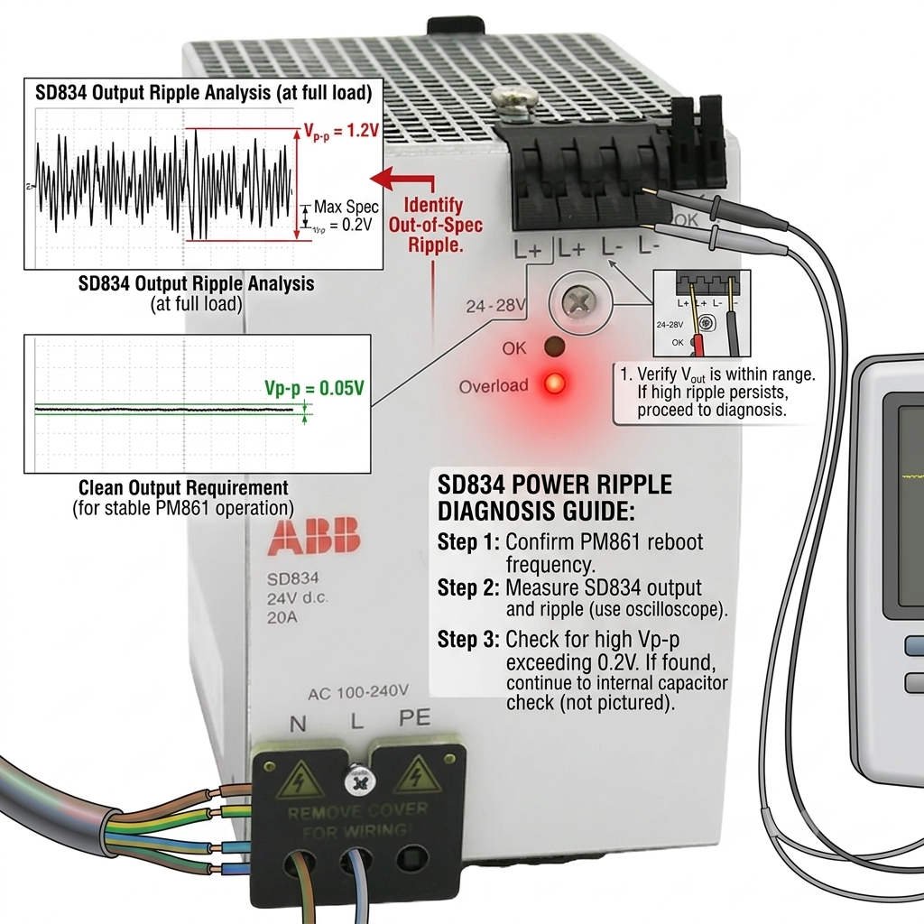
To accurately evaluate power supply health, engineers must analyze output ripple, hold-up time, and Equivalent Series Resistance (ESR). Standard factory specifications state that a healthy SD834 module must maintain a peak-to-peak ripple voltage well below 100mVp-p.

Output Ripple Peak-to-Peak (mVp-p)Risk Assessment LevelRecommended Action Plan
< 100 mVp-pNormal OperationContinue routine annual monitoring.
100 to 200 mVp-pMarginal DegradationIncrease inspection frequency.
200 to 500 mVp-pSignificant Capacitor DecaySchedule module replacement soon.
> 500 mVp-pCritical Failure RiskReplace the power supply immediately.

As electrolytic capacitors age, their chemical electrolyte gradually dries out, which causes the ESR to spike exponentially. According to the industry-standard Arrhenius “10°C Rule,” the operational lifespan of an electrolytic capacitor halves with every 10°C increase in ambient operating temperature. Inside poorly ventilated cabinet environments where temperatures exceed 45°C, an SD834 module nearing 5 to 8 years of continuous service poses a high risk for sudden voltage drops during transient load steps, leading to CPU power failure logs.

Step-by-step guide for online oscilloscope ripple measurement

Validating power quality requires capturing high-frequency noise that standard tools miss, meaning a digital oscilloscope is required for accurate diagnostic testing.

  • Step 1: Establish the measurement point
    Always connect your test probes directly to the +24V and 0V output terminals of the SD834 module. Do not measure at a distant I/O terminal block because long cable runs introduce external electromagnetic interference (EMI) and line voltage drops that skew your baseline data.
  • Step 2: Configure the oscilloscope parameters
    Set the input channel coupling to AC to block the 24VDC offset. Limit the channel bandwidth to 20MHz to filter out irrelevant high-frequency ambient radio noise. Utilize a standard 10X attenuation probe and set your time base to 5ms/div with a vertical sensitivity of 50mV/div.
  • Step 3: Utilize a spring ground lead
    Discard the standard long alligator ground clip during this test. A long ground wire acts as an antenna that absorbs stray ambient noise, creating false voltage spikes. Instead, use a short metallic ground spring directly at the probe tip to achieve a clean, accurate signal path.
  • Step 4: Execute tests under full load
    Never evaluate a power supply solely under open-circuit or no-load conditions. Ensure the system is operating normally with all PM861 processors, communication links, and I/O cards fully energized to observe the true worst-case ripple profile.

Advanced diagnostic testing via load perturbation

If an oscilloscope is unavailable on-site, a high-end digital multimeter featuring dual AC+DC measurement capabilities can serve as an initial screening tool. A healthy 24VDC rail should display an AC component below 30mVAC. If the value exceeds 100mVAC, further validation is required.

To confirm capacitor aging without opening the hardware casing, engineers can perform a controlled load perturbation test. First, record the baseline AC ripple voltage of the running system. Next, temporarily connect a safe, auxiliary resistive load to increase the power draw by 10% to 20%. If the ripple voltage jumps by more than 50% or if the PM861 status LEDs flicker, the internal capacitors have lost their buffering capacity due to elevated ESR, signaling that the module requires immediate refurbishment.

Industrial Application Scenario: Petrochemical Compressors

Consider a real-world scenario involving a major petrochemical plant utilizing an ABB AC800M controller to manage a critical gas compressor train. The system suffered from spontaneous, unprovoked PM861 reboots every few weeks, disrupting production.

Plant technicians initially suspected a processor firmware glitch or a localized grounding loop. However, an on-site oscilloscope evaluation revealed that while the steady-state voltage read a clean 24.02VDC on a multimeter, the actual peak-to-peak ripple voltage spiked to 620mVp-p whenever the cabinet cooling fans cycled on. Replacing the decade-old SD834 hardware immediately restored clean power and eliminated the erratic controller trips, saving the facility thousands of dollars in potential emergency downtime.

If your facility relies on aging legacy hardware to maintain continuous production, proactive hardware renewal is crucial. Explore our comprehensive inventory of verified, high-reliability control components and power solutions at Powergear X Automation to secure your system’s uptime.

Frequently Asked Questions (FAQ)

Q1: Should I immediately replace the PM861 CPU if it registers a “Power Failure” reboot log?

No. Field data indicates that over 70% of random controller reboots stem from poor external power quality or aging power supplies rather than physical defects within the CPU itself. Always verify the output ripple voltage and terminal torque tightness of your SD834 module before condemning expensive processor hardware.

Q2: What is the typical operational lifespan of an ABB SD834 power module?

While industrial power supplies do not feature a fixed expiration date, their internal electrolytic capacitors degrade predictably over time. In optimal environments (under 25°C), these modules reliably serve for 8 to 10 years. In hotter process environments (above 45°C), preventive replacement should occur every 4 to 6 years.

Q3: Can I mix different product revisions of the SD834 during a live system replacement?

Yes, newer revisions of the SD834 are generally backward compatible with older AC800M controller chassis. However, prior to executing a hot-swap or live migration, always cross-reference the official ABB hardware compatibility matrix against your specific 800xA system firmware version to prevent minor revision mismatches from disrupting the redundant power bus.

Correcting AGND and DGND Ground Loops on DCS Modules

Fixing ABB DCS 07AI91 Analog Input Fluctuations via AGND and DGND Isolation

In industrial automation, field engineers frequently encounter signal instability on analog input modules. Specifically, the ABB DCS 07AI91 analog input card often exhibits severe data fluctuations or random process variable (PV) jumps. While many technicians immediately suspect faulty transmitters or bad analog-to-digital (A/D) converters, the root cause usually lies elsewhere. Improper grounding of the Analog Ground (AGND) and Digital Ground (DGND) on external terminals creates devastating ground loops.

Managing high-precision analog inputs requires strict adherence to single-point grounding principles. If you mismanage these reference points, electrical noise will easily corrupt your low-level loops. Consequently, control room operators will notice erratic spikes on their trend screens. This technical guide delivers practical solutions to eliminate ground-loop interference and restore rock-solid signal stability to your control systems.

The Operational Cost of Signal Noise in Process Automation

The 07AI91 analog input module serves as a critical data gateway by converting 4-20mA and 0-10V field signals into digital values. In continuous processing industries like oil and gas, chemical manufacturing, and power generation, accurate analog measurements directly determine PID loop performance. Therefore, minor signal fluctuations can destabilize an entire production line.

At Powergear X Automation, we observe that incorrect AGND and DGND terminal wiring damages control quality even when field instruments operate perfectly. Experienced engineers know that optimizing the external grounding architecture resolves signal jumping far more effectively than replacing expensive hardware. Protecting signal integrity ensures tighter process control, lowers equipment stress, and reduces unplanned downtime.

Deconstructing 07AI91 Technical Specifications and Noise Vulnerability

High-resolution A/D converters make the 07AI91 module highly sensitive to subtle process changes. However, this extreme precision also renders the card vulnerable to common-mode voltage noise. When the grounding system is poorly designed, the high-resolution architecture inadvertently amplifies electrical interference instead of filtering it out.

Field data indicates that if a process variable jumps by 1% to 3% while the actual physical process remains steady, grounding layout errors are usually the culprit. Although the 07AI91 features internal galvanic isolation, this feature cannot compensate for external wiring blunders. Industrial isolation shields the internal system bus from field faults; it does not grant permission to create arbitrary external ground paths.

Step-by-Step Field Guide to AGND and DGND Terminal Wiring

To eliminate data jumping on the 07AI91 module, you must strictly isolate AGND and DGND on your external marshalling terminals. Please follow these verified deployment steps to ensure clean signal acquisition:

  • Enforce Single-Point Grounding: Never bridge the AGND and DGND terminals together at the field terminal block. ABB engineers design these systems to connect at a single, controlled reference point inside the cabinet chassis.
  • Isolate Terminal Connections: Route the AGND wire exclusively to the analog signal reference plane and keep the DGND dedicated to digital logic returns.
  • Prevent Ground Loops: Double-bonding these grounds creates a closed loop that invites stray electromagnetic currents to circulate through your analog loops.

Optimizing Shield Grounding and 24VDC Power Quality

Proper cable shield management provides the next line of defense against factory automation noise. Technicians must terminate instrument cable shields solely at the control cabinet side using a dedicated copper ground bar. Leaving the field instrument side ungrounded prevents earth potential differences from driving current through the shield.

In addition, you must verify the quality of your 24VDC power distribution system. Use an oscilloscope to measure DC power ripple, ensuring it stays well below 100mV peak-to-peak. Furthermore, check the AC voltage between AGND and the Protective Earth (PE) bus. If this potential difference exceeds 1VAC, you must systematically audit your plant-wide grounding grid to locate the leakage source.

Strategic Cable Routing in High-Interference Environments

Heavy electrical machinery like variable frequency drives (VFDs), large motors, and soft starters generate massive electromagnetic fields. To safeguard your low-voltage analog loops, you must maintain rigid physical separation during cable installation. Run your analog signaling lines in separate, grounded steel conduits or distinct cable tray tiers.

Always maintain a minimum clearance of 300mm between parallel analog lines and high-voltage power cables. When signal and power runs must intersect, cross them strictly at a 90-degree right angle to minimize inductive coupling. These clean installation habits eliminate the vast majority of ghost faults that engineers mistake for hardware failures.

Industrial Case Study: Resolving Flow Meter Fluctuations

During a recent DCS upgrade at a major chemical plant, an engineer reported that a critical electromagnetic flow meter exhibited severe PV jumping after commissioning. The trend line showed random 2.5% spikes every few minutes, causing the downstream pneumatic control valve to stroke erratically. The site team initially suspected a defective 07AI91 card and replaced it twice, yet the problem persisted.

A deep audit by our team revealed that the installation contractor had jumpered AGND to DGND on the marshalling terminal strip to “simplify” wiring. This link allowed high-frequency noise from a nearby 110kW cooling pump VFD to feedback directly into the analog return path. By removing the external jumper and isolating the grounds according to standard factory automation specs, the flow meter signal stabilized instantly, proving the value of proper grounding rules.

Explore Premium Automation Hardware Solutions

Resolving complex signal anomalies requires both expert field practices and dependable control hardware. If you are looking to replace legacy components, expand your current DCS architecture, or source hard-to-find industrial control modules, we can assist you. Discover our comprehensive inventory of high-performance components and technical spares by visiting the Powergear X Automation platform today.

Frequently Asked Questions

Q1: Does a jumping PV value always indicate that the 07AI91 card is physically damaged?
No, physical hardware failure is actually rare. Field statistics show that roughly 50% of analog jump issues stem from grounding errors, 30% come from electromagnetic interference (EMI), and 15% relate to field transmitter faults. Less than 5% point to actual component degradation.

Q2: Can I ground both ends of an analog signal shield for extra protection?
Absolutely not. Grounding both ends of a shield creates a classic ground loop because different areas of a factory campus always have slightly different earth potentials. This voltage delta drives circulating currents through your shield, which induces heavy noise into your signal pairs via transformer action.

Q3: What are the main compatibility checks needed when replacing an older ABB analog card with a 07AI91?
You must verify the master controller firmware version, backplane bus compatibility, and your engineering software database configuration. Always check the manufacturer’s official compatibility matrix to ensure your channel assignments and signal range configurations map correctly without dropping data.

Fixing IMFCS01 Pulse Counter Failures in Turbine Speed Loops

Resolving IMFCS01 Pulse Counting Failures in Steam Turbine Speed Control Systems

Reliable speed measurement remains a critical pillar of turbomachinery protection and load control within industrial automation. In distributed control systems (DCS), the ABB Bailey INFI 90 / Symphony series IMFCS01 Frequency Counter Module plays a vital role. This module frequently conditions and counts pulse signals generated by proximity probes and preamplifiers (Proximitors). However, engineers often encounter a frustrating scenario during commissioning or post-overhaul restarts. The Proximitor functions correctly, and signal cables show excellent continuity, yet the IMFCS01 module registers a wheel speed of zero RPM. This comprehensive guide diagnoses this common field issue and offers actionable technical solutions.

Understanding Why the IMFCS01 Fails to Capture Turbine Pulse Signals

A typical steam turbine speed measurement loop routes a proximity probe through a Proximitor to output pulses directly into the IMFCS01 module. Many control room technicians overlook the fundamental operation of the hardware. The IMFCS01 does not directly read raw frequency. Instead, internal comparator circuits must detect a pulse crossing a predefined voltage threshold before registering a count. If field personnel misconfigure this threshold higher than the actual peak voltage of the incoming wave, the card remains blind to the pulse edges. Industrial facilities frequently experience this issue after turbine overhauls, sensor replacements, or when splitting speed loops to feed third-party vibration monitoring systems like Bently Nevada 3500 racks.

Consider the following signal interaction matrix based on real-world field data:

Preamplifier Output (Vpp)IMFCS01 Threshold SettingCounting StatusOperational Outcome
2.5V Pulse5V (Mid Threshold)No CountingZero RPM Reading / False Trip Hazard
8.0V Pulse5V (Mid Threshold)Normal CountingStable Speed Control
12.0V Pulse10V (High Threshold)Normal CountingStable Speed Control
3.0V Pulse10V (High Threshold)No CountingDCS Speed Signal Loss Fault

The Critical Role of Threshold Configuration in Rotating Machinery Protection

The primary value of the IMFCS01 lies in providing high-integrity speed processing for safety-critical control systems. In petrochemical plants, power generation facilities, and gas pipelines, sudden speed signal loss triggers devastating consequences. For example, according to API 670 standards for machinery protection, a loss of speed feedback can cause emergency overspeed trip valves to close unexpectedly. Consequently, these nuisance trips result in massive financial losses due to unplanned production downtime. Properly managing input sensitivity via physical hardware jumpers significantly improves signal-to-noise ratios, especially when processing attenuated signals across long field cable runs.

Step-by-Step Procedure to Adjust the IMFCS01 Threshold Jumper

While minor board variations exist across different manufacturing generations of the Bailey INFI 90 hardware, most modules utilize a standardized jumper layout. Technicians should execute the following steps to ensure precise calibration:

Step 1: Measure the Actual Pulse Amplitude
Connect an isolated, calibrated digital oscilloscope directly to the terminal block of the speed input channel. Do not rely solely on a digital multimeter, as multimeters average out the voltage. Record the peak-to-peak voltage (Vpp), the low state voltage, and the wave shape. For example, if a probe yields a 0V low state and a 4.2V high state at 3,000 Hz, the effective pulse peak is 4.2V.

Step 2: Inspect the Hardware Jumper Configuration
Isolate the loop power and safely extract the IMFCS01 card from its module mounting slot. Locate the hardware jumpers on the printed circuit board (PCB), typically labeled as JP1, JP2, JP3, or designated under a “Threshold Select” silk screen. Review the standard voltage matrix:

  • LOW Position: Activates a 1V to 2V threshold for low-voltage pulses.
  • MID Position: Establishes a nominal 5V threshold for standard industrial logic.
  • HIGH Position: Sets a 10V threshold designed for high-amplitude signals.

Step 3: Apply the 40% to 60% Field Engineering Rule
As a rule of thumb gained from decades of plant maintenance, always configure the threshold to sit between 40% and 60% of the true pulse peak voltage. If the measured pulse peak is 4.2V, the 10V high setting will fail entirely. Therefore, move the jumper to the LOW threshold position (1-2V) to guarantee robust triggering across all turbine operational speeds.

Step 4: Re-energize and Verify Control Loops
Reinsert the module, power up the rack, and monitor the DCS graphics. Verify the RPM display, check the Sequence of Events (SOE) logs for chatter, and trend the speed variable. If the speed curve remains flat and free of noise spikes, the threshold is correct.

Technical Specifications and Environmental Challenges

Managing turbine speed inputs requires balancing three key engineering parameters:

  • Input Edge Detection: Setting the threshold too high causes dropped counts, while setting it too low invites high-frequency noise interference. Engineers must adapt these settings when field cables exceed 100 meters, as cable capacitance degrades signal amplitude by up to 30%.
  • Maximum Frequency Limits: Consider a 60-tooth speed wheel spinning at 10,000 RPM. The input frequency reaches exactly 10,000 Hz ($10,000 \times 60 \div 60 = 10,000\text{ Hz}$). If this approach nears the upper processing limits of your I/O card, it introduces processing lag and timing errors into overspeed protection logic.
  • Galvanic Isolation: Turbine decks contain severe electromagnetic interference (EMI) from high-voltage generators, exciters, and variable frequency drives (VFDs). The integrated opto-isolation on the IMFCS01 protects internal logic from common-mode voltage spikes and reduces false overspeed trips.

Best Practices for Field Installation and Maintenance

🔧 Quick Field Checklist for Speed Loops:
1. Always routing speed signal cables through dedicated, grounded galvanized conduits.
2. Maintain a minimum 30cm separation between pulse signal lines and high-voltage AC cables.
3. Ensure the overall cable shield is grounded at a single point, preferably at the DCS cabinet ground bus.

Furthermore, plants located in areas prone to lightning must install dedicated signal surge protective devices (SPDs) on the DIN rail before the signal enters the IMFCS01 card. This prevents induced high-voltage transients from burning out the delicate comparator circuits inside the module.

An Expert Commentary from Powergear X Automation

From our perspective at Powergear X Automation, many control system issues blamed on “dead I/O cards” actually stem from simple configuration oversights. As legacy control systems interface with modern instrumentation, voltage mismatches occur more frequently. When upgrading or maintaining critical infrastructure, ensuring proper impedance and threshold matching saves hundreds of hours of troubleshooting. If you require verified, high-reliability replacement parts or upgraded modules for your legacy control systems, explore the fully tested inventory available at Powergear X Automation to secure your plant’s operational uptime.

Real-World Application Scenario

During a recent turnkey upgrade at a combined-cycle power plant, the plant replaced an old mechanical overspeed governor with a triple-modular redundant electronic system. Technicians routed the secondary speed pulses into an existing Bailey INFI 90 DCS running an IMFCS01 card. Upon startup, the DCS showed zero RPM, instantly triggering a start-failure lock. While the team initially suspected a faulty module, an oscilloscope check revealed that the new sensor only outputted a 3.8V peak signal because of an added safety barrier line resistance. The IMFCS01 jumper was set to the default MID (5V) position. Moving the jumper to the LOW position resolved the issue instantly, allowing the plant to synchronize to the grid on schedule.

Frequently Asked Questions (FAQs)

Q1: Does a flat-line zero RPM reading on the IMFCS01 mean the module must be replaced?
No, a zero reading rarely indicates immediate hardware failure if the card status LEDs are normal. Most incidents stem from incorrect threshold jumper settings, oxidized terminal connections, or signal attenuation caused by long field wiring. Always check the pulse waveform with an oscilloscope before purchasing replacements.

Q2: Can the IMFCS01 handle direct TTL signals from modern digital encoders?
Yes, provided the TTL signal voltage levels cross the configured threshold. Since standard TTL high states sit around 5V, the MID or LOW threshold jumper settings must be verified on the card to ensure the module registers the rising and falling edges accurately.

Q3: How does cable length affect the threshold settings on frequency counter modules?
Longer cables increase total loop resistance and capacitance, which rounds off the sharp edges of square waves and reduces the peak voltage. A pulse that leaves a Proximitor at 5V might arrive at the control cabinet at 3.2V. In these cases, technicians must lower the threshold jumper to compensate for this signal degradation.

Bently Nevada 3500/53 Online Configuration & Trip Speed Guide

Can You Modify Bently Nevada 3500/53 Trip Speed Online? Safety Logic and Risks Explained

Modifying safety parameters in a machinery protection system requires deep technical caution. In the industrial automation sector, the Bently Nevada 3500/53 Electronic Overspeed Detection System safeguards critical rotating machinery. However, field engineers often debate whether the 3500 Rack Configuration Software allows users to modify the Trip Speed parameter while the turbine is running. The short answer depends on your system configuration, firmware version, and active safety protocols.

The Real Risks of Online Trip Speed Modifications

According to API 670 standards for machinery protection systems, operators should never alter safety-critical setpoints during machine operation. However, the Bently Nevada software environment does not always enforce a hard block on online changes. Depending on your specific system setup, an online download of a modified overspeed setpoint typically triggers one of two technical behaviors.

Scenario 1: Pending Activation Status
In newer firmware versions, the software accepts the configuration download but places the new Trip Speed into a “Pending” state. The module continues to use the old setpoint until the hardware undergoes a manual reset or a power cycle. Field engineers must remember that a “Download Successful” message does not mean the new overspeed protection value is live.

In contrast, older legacy systems or racks with relaxed security permissions might allow immediate execution. In this scenario, the overspeed setpoint changes in real time. If a technician accidentally inputs an incorrect value, the machine could lose its safety margin instantly, risking catastrophic mechanical failure during a transient surge.

Why Independent Overspeed Protection Matters in DCS and PLC Environments

The Bently Nevada 3500/53 module does not serve as a standard speed transmitter. Instead, it operates as an independent safety layer separate from the primary Distributed Control System (DCS) or Programmable Logic Controller (PLC). In factory automation plants, control systems can experience communication lag or processor overruns.

Therefore, the 3500/53 system must act autonomously. If the primary governor control fails, this module executes an emergency trip within milliseconds. This rapid response prevents rotor destruction in high-stakes applications like refinery compressors, steam turbine generators, and LNG expansion trains.

Technical Insights: Voting Logic and Configuration Security

To deliver maximum reliability, the 3500/53 module utilizes advanced voting logic, typically configured in a 2oo3 (Two Out of Three) architecture. Three independent proximity probes measure the shaft speed simultaneously. The system triggers a trip output only when at least two channels confirm an overspeed condition.

If you attempt an online configuration modification and cause a parameter mismatch between channels, you risk disrupting this voting logic. To eliminate this vulnerability, facility managers must enforce strict hardware-based security:

  • Keep the physical rack keyswitch turned to the RUN Position to block unauthorized software writes.
  • Enable software-level configuration locks and password hierarchies.
  • Enforce a strict Management of Change (MOC) policy before connecting any configuration PC.

Installation and Maintenance Best Practices for Field Engineers

Experienced automation professionals follow rigid guidelines when maintaining speed detection hardware. To ensure plant safety, always apply the following field rules:

  1. Execute Changes Only During Shutdown: Schedule all overspeed adjustments during planned maintenance windows when the rotor is completely stationary.
  2. Verify Measurement Units Carefully: Always double-check your units before hitting download. Mistaking Hertz (Hz) for Revolutions Per Minute (RPM), or entering an incorrect gear tooth count, will corrupt the safety calculation.
  3. Audit the System Event Logs: After any configuration upload, review the System Event List to confirm that the hardware accepted the parameters without generating a channel fault.

Powergear X Automation Insight: Hardware Lifecycle Strategy

Our Perspective: At Powergear X Automation, we observe that many industrial sites run Bently Nevada 3500 racks that have been in continuous operation for over a decade. While these systems are remarkably durable, running obsolete firmware creates unnecessary operational risks. Firmware mismatches between old hardware modules and newer PC configuration software frequently cause corrupt downloads or false diagnostics.

We recommend conducting a comprehensive audit of your machinery protection assets every five years. Upgrading your modules ensures full compliance with modern safety standards and guarantees clean integration with your broader plant control systems.

Industrial Application Scenario: Petrochemical Compressor Protection

Consider a large-scale centrifugal compressor driven by a steam turbine in a petrochemical plant. The plant utilizes a Rockwell Automation Allen-Bradley ControlLogix PLC for process sequencing and a Honeywell Experion DCS for continuous loop control. However, the critical overspeed trip logic resides solely in a Bently Nevada 3500 rack equipped with a 3500/53 module configured in 2oo3 voting logic.

During an annual turnaround, engineers needed to update the turbine trip speed from 4,200 RPM to 4,150 RPM based on new OEM design limits. Instead of performing an unapproved online modification while idling, the team utilized the plant’s outage window. They switched the physical rack keyswitch to PROGRAM, verified the tooth-to-frequency scaling factors, uploaded the new configuration, switched the key back to RUN, and simulated a speed signal to validate the trip relays before startup. This disciplined approach prevented accidental trips and ensured complete compliance with insurance and safety regulations.


Frequently Asked Questions

Q1: What happens if a 3500/53 channel experiences a sensor fault during operation?
In a standard 2oo3 configuration, if one proximity probe fails or loses its signal, the module flags a channel fault error but does not trip the machine. The voting logic automatically degrades to a 1oo2 (One Out of Two) safety structure, allowing the plant to continue running safely while maintenance teams replace the faulty sensor.

Q2: Can I mix old firmware modules with new software versions?
While Bently Nevada software provides backward compatibility, severe gaps between old module firmware and modern software versions can block specific parameter changes or cause communication timeouts. Always check the official compatibility matrix before attempting to modify parameters.

Q3: Is the 3500/53 module interchangeable with standard 3500/50 tachometer modules?
No, they serve different purposes. The 3500/50 is a standard tachometer designed for speed measurement, reverse rotation detection, and zero-speed tracking. The 3500/53 is a highly specialized, fast-response safety module dedicated solely to emergency overspeed protection and complies with rigorous international safety standards.


Looking to replace obsolete modules, source certified spare parts, or optimize your industrial control systems? Discover reliable hardware solutions and technical support by visiting Powergear X Automation today.

Configuring Bently Nevada 3500-61-04-01 Inputs Control Systems_

Configuring Bently Nevada 3500/61-04-01 Inputs | Control Systems

Optimizing Bently Nevada 3500/61-04-01 Temperature Monitor Inputs for Industrial Control Systems

Enhancing Signal Integrity in Factory Automation Architectures

Modern industrial automation relies on precise data to maintain process safety and equipment uptime. The Bently Nevada 3500/61-04-01 temperature monitor acts as a critical line of defense for heavy machinery protection. This module processes crucial thermal data from resistance temperature detectors (RTDs) and thermocouples. Engineers must correctly configure channel inputs to prevent measurement errors in noisy plant environments. Choosing between single-ended and differential wiring layout directly impacts how safely your machinery operates. Powergear X Automation regularly observes that upfront configuration choices dictate long-term system stability.

Configuring Bently Nevada 3500-61-04-01 Inputs Control Systems_

Configuring Bently Nevada 3500-61-04-01 Inputs Control Systems

Analyzing Single-Ended Mode in Standard Control Environments

Single-ended input configuration references all incoming sensor signals to a shared system ground. This setup simplifies factory automation wiring because it requires fewer physical conductors per channel. Consequently, it lowers initial installation costs and reduces terminal density inside marshalling cabinets. However, this approach carries distinct technical risks in distributed control systems (DCS). Ground potential differences across long distances can introduce significant voltage offsets. Therefore, you should restrict single-ended measurements to short cable runs under 15 meters. Only deploy this mode where localized electrical noise is completely negligible.

Deploying Differential Inputs for High-Noise PLC Networks

Differential input mode measures the voltage variance between two dedicated signal lines instead of ground. As a result, the monitor effectively cancels out common-mode voltage that affects both wires simultaneously. This design provides superior noise immunity in dense programmable logic controller (PLC) environments. Heavy industrial facilities contain numerous variable frequency drives (VFDs) and high-power switching systems. These devices generate massive electromagnetic interference (EMI) that disrupts weak sensor signals. Therefore, differential configuration serves as the benchmark choice for long-distance runs and critical machine skids.

Combating Ground Loops to Maximize Machine Availability

Ground loops represent a frequent source of erratic temperature readings and false alarms during commissioning. When multiple ground points exist at different electrical potentials, stray currents flow through signal shields. Differential wiring isolates the measurement circuit from these ground loops entirely. At Powergear X Automation, our field experience shows that differential configurations eliminate up to 90% of intermittent signal spikes. Eliminating these spikes prevents nuisance trips on high-value assets like turbines and compressors. Consequently, maintaining true signal isolation directly improves overall plant availability and lowers maintenance overhead.

Implementing Field-Proven Shielding and Installation Tactics

Proper physical installation must accompany your software configuration to achieve optimal E-E-A-T technical compliance. Always terminate instrumentation cable shields at a single point, typically inside the local control cabinet. Dual-ended grounding inadvertently creates a path for circulating ground currents. Furthermore, maintain a minimum physical separation of 30 centimeters between low-voltage signal lines and high-voltage power cables. If you deploy sensors in outdoor areas or lightning-prone zones, integrate external surge protection devices. Following these field-tested practices preserves the integrity of your hardware investment over decades.

Evaluating Long-Term Lifecycle Costs of Monitor Configuration

Engineering teams often face pressure to minimize initial wiring costs during fast-paced plant construction. While single-ended setups save minor labor hours upfront, they frequently inflate troubleshooting costs later. Technicians spend days diagnosing ghost alarms caused by changing plant electrical loads. Conversely, standardized differential wiring provides consistent, predictable data trends from day one. Powergear X Automation strongly recommends adopting differential input modes as your default corporate engineering standard. This proactive strategy ensures dependable asset protection throughout the entire lifecycle of your machinery.

Industrial Application Scenario: Turbocompressor Protection

Consider a large-scale centrifugal compressor operating on a petrochemical production site. The asset utilizes multiple Pt100 RTDs to track critical radial bearing temperatures over a 60-meter distance. Initially, the system utilized single-ended wiring to save terminal space. However, whenever the main 500kW VFD motor ramped up, the temperature readings spiked erratically, triggering false warning logs. Technicians resolved the issue completely by rewiring the sensors into differential mode. This simple change eliminated the VFD-induced common-mode noise, ensuring stable operations and zero false trips.

Frequently Asked Questions

  • Can I mix single-ended and differential channels on the same 3500/61 module?
    Yes, the Bently Nevada 3500 configuration software allows independent channel selection. However, you must ensure the underlying hardware I/O termination blocks match the specific wiring topology chosen for each channel.
  • What are the signs that my single-ended temperature channel suffers from EMI?
    Look for rapid, non-physical temperature fluctuations on your HMI trend screens, such as a 10-degree jump within a single second. These spikes usually correlate with the starting or stopping of nearby heavy motors or VFDs.
  • Does changing to differential mode require different sensor types?
    No, standard 3-wire or 4-wire RTDs and standard thermocouples inherently support differential connection schemes. The modification occurs entirely at the monitor terminal block and within the system software settings.

Procuring Reliable Automation Components

Sourcing genuine machinery protection hardware is vital for keeping your critical operations safe and efficient. Explore the comprehensive catalog at Powergear X Automation to find authentic control components, replacement modules, and expert technical support tailored to your plant needs.

Bently Nevada 3500-42M 140734-02 Grounding Best Practices_

Bently Nevada 3500/42M 140734-02 Grounding Best Practices

Eliminating 50Hz Interference: Grounding the Bently Nevada 3500/42M 140734-02

Understanding Grounding Challenges in Control Systems

The Bently Nevada 3500/42M Proximitor/Seismic Monitor, utilizing the 140734-02 rear I/O, is a staple in industrial automation. However, engineers often face 50Hz power frequency interference that triggers false vibration alarms. We observe that these issues frequently stem from improper COM and safety ground management. Maintaining signal integrity requires precise grounding techniques to ensure accurate data within your DCS or PLC infrastructure.

Bently Nevada 3500-42M 140734-02 Grounding Best Practices_

Bently Nevada 3500-42M 140734-02 Grounding Best Practices_

The Role of the COM Terminal

Many technicians mistakenly bond the COM terminal to multiple plant grounding points. The COM terminal acts as a signal reference, not a protective earth. Connecting it to several locations creates ground loops that inject 50Hz noise into your vibration signals. This interference degrades measurement accuracy and compromises your factory automation monitoring performance. You must keep the COM terminal isolated from the safety ground path to prevent circulating currents.

Implementing Single-Point Grounding

Industry standards, including API 670 guidelines, recommend a single-point grounding strategy for signal commons. This approach forces all return currents through one controlled path. Follow these steps to optimize your installation:

  • Identify one designated grounding point inside your control cabinet.
  • Connect the signal common to this point only.
  • Ensure the cabinet ground bar links directly to the plant safety ground.
  • Route sensor cables away from high-current power conductors.
  • Verify that shields terminate correctly according to manufacturer specifications.

Strategic Insights from Power Gear X Automation Limited

Based on our field experience, approximately 75% of noise-related issues result from poor shielding rather than hardware defects. Before replacing your 3500/42M module, perform a thorough inspection of your cabling. Check for electromagnetic interference (EMI) near VFDs and large motors. If you continue to see stable 50Hz peaks across multiple channels, your grounding topology likely requires a professional review. For expert support or authentic Bently Nevada components, please visit Power Gear X Automation Limited.

Troubleshooting and Best Practices

  • ⚙️ Measure AC voltage potential between the cabinet and machine frame.
  • 🔧 Isolate shield connections during testing to identify ground loop sources.
  • ✅ Use high-quality shielded twisted-pair instrumentation cables for all sensors.
  • ⚙️ Install galvanic isolation for sensors located over 100 meters away.
  • 🔧 Inspect all terminal block connections for corrosion or loose wires.

Frequently Asked Questions

Q1: How can I distinguish electrical interference from mechanical vibration faults?
Electrical noise usually presents as a constant 50Hz frequency peak across multiple channels. Mechanical faults typically track with the machine’s running speed. If the noise disappears when you isolate the cable shield, the issue is almost certainly grounding-related.

Q2: Why does my vibration reading fluctuate when a nearby motor starts?
This indicates electromagnetic coupling or a ground loop issue. Large motors generate significant EMI. If your signal cables lack proper shielding or run parallel to motor power lines, the monitor will pick up induced noise during high-load operations.

Q3: Should I always replace the 140734-02 module when I see 50Hz noise?
Replacement is rarely the first solution. Our team at Power Gear X Automation Limited suggests performing a systematic grounding audit first. Hardware failure in the 3500 system is uncommon compared to environmental and installation-related signal corruption.

How to Power Photoelectric Keyphasor via Bently Nevada 3500/40M

How Does the Bently Nevada 3500/40M Keyphasor Module Supply 15VDC Power to a Photoelectric Sensor?

Understanding the Role of Keyphasor Modules in Factory Automation

Reliable machinery protection systems form the backbone of modern industrial automation. Within these setups, the Bently Nevada 3500/40M Proximity Keyphasor Module plays a critical role. It captures essential shaft reference signals for rotational speed measurement, phase analysis, and critical vibration diagnostics.

When engineers select a photoelectric sensor as the primary input device, commissioning often brings up a practical engineering challenge. Technicians frequently wonder if the 3500/40M Rear I/O module can directly supply the required 15VDC operating power. Powergear X Automation presents this comprehensive technical guide to clarify wiring configurations, electrical compatibility, and best practices for the field.

Analyzing the Core Engineering Value for Critical Machinery

The 3500/40M Keyphasor system generates a vital once-per-revolution pulse to synchronize vibration data across the entire PLC and DCS infrastructure. Without an accurate reference pulse, advanced diagnostics like orbit analysis, shaft centerlines, and rotor balancing calculations fail.

Industrial facilities in the oil & gas, petrochemical, and power generation sectors rely on these continuous data streams. According to EPRI (Electric Power Research Institute) reliability statistics, improper instrumentation accounts for over 30% of false machinery trips. Utilizing the internal 15VDC supply simplifies field installations. Consequently, this design choice eliminates external power supplies and significantly reduces complex cable routing.

Technical Deep Dive: The 15VDC Excitation Circuit and Signal Integrity

The standard internal circuitry of specific 3500/40M Rear I/O modules includes a regulated excitation voltage output. This hardware path routes a steady 15VDC directly to the designated sensor power terminal blocks.

  • Component Redundancy: Direct wiring removes independent external power supplies, which reduces the total bill of materials (BOM).
  • Ground Isolation: Utilizing the internal power loop minimizes the risk of ground loops between the machinery skid and the control cabinet.
  • Design Simplification: Fewer active devices inside the marshalling panel streamline future maintenance tasks.

However, field engineers must verify the exact bill-of-materials part number before wiring. Certain legacy hardware revisions or specific isolated I/O variants alter this standard power distribution model.

Evaluating Sensor Output Formats and Digital Compatibility

Photoelectric sensors commonly feature diverse electronic output stages. These variants typically include open-collector, NPN, PNP, or TTL pulse outputs. The Bently Nevada 3500/40M module requires highly precise voltage thresholds and sharp edge transitions to register a valid event.

Sensor Output TypeCompatibility with 3500/40MRequired Action / Engineering Verification
NPN Open-CollectorFully CompatibleRequires correct pull-up resistor configuration via internal jumpers.
PNP Voltage PulseCompatibleMatch peak voltage limits with the module’s input thresholds.
TTL Level (5V)Moderately CompatibleVerify threshold settings within the 3500 Rack Configuration Software.

An incompatible configuration can lead to missing pulses or corrupted speed readings. Therefore, engineers must match sensor electrical data sheets with the monitoring system specifications rather than assuming universal interoperability.

Optimizing Pulse Response Times for High-Speed Turbomachinery

The Keyphasor card monitors rapid pulse edge transitions rather than smooth, continuous analog voltage variations. As a result, the switching frequency and response time of your photoelectric sensor directly dictate system accuracy.

In high-speed applications like gas turbines or centrifugal compressors, sluggish sensor response times cause phase jitter. This timing drift severely distorts balancing routines. Powergear X Automation recommends industrial-grade optical sensors with high ambient light rejection and microsecond response times. This step ensures consistent tracking during transient machine conditions, such as rapid startups or emergency trips.

Step-by-Step Commissioning and Field Installation Guide

Engineers must adhere to precise electrical checks during initial commissioning to ensure long-term system reliability.

  1. Verify the Current Budget: Confirm that the current draw of the photoelectric sensor does not exceed the maximum mA rating of the Rear I/O module.
  2. Configure Module Jumpers: Open the module housing to set internal jumpers for the correct input signal type (e.g., Proximitor or Magnetic Picker/Digital).
  3. Terminate Power Connections: Wire the sensor positive lead to the +15VDC terminal and the common lead to the COM terminal on the Rear I/O connector block.
  4. Connect Signal Channels: Land the sensor pulse output line on the dedicated SIG terminal of the respective Keyphasor channel.
  5. Verify the Waveform: Use an oscilloscope to inspect the pulse wave shape directly at the rack terminals while the machine rotates.

Mitigating Noise Interference via Grounding and Shielding Protocols

Machinery skids often generate significant electromagnetic interference (EMI) due to nearby variable frequency drives (VFDs) and high-power motor leads. Field experience indicates that poor shielding causes most intermittent Keyphasor failures.

  • Always use high-quality twisted, shielded instrument cables for all field runs.
  • Terminate the cable shield only at the 3500 rack ground bar to prevent dangerous ground loops.
  • Keep signal lines isolated from high-voltage AC power trays by maintaining at least 12 inches of physical separation.

Following these clean-wiring principles prevents unwanted electrical noise from triggering false speed readings or unexpected system shutdowns.

Protecting Outdoor Infrastructure Against Surge Transients

Photoelectric hardware mounted on outdoor cooling towers or exposed offshore skids faces continuous risk from lightning and surge transients. Industrial plants can prevent costly module damage by integrating specific physical protections.

  • Install dedicated DIN-rail surge protection devices (SPDs) inside local field junction boxes.
  • Ensure the metal sensor housing maintains a low-resistance path to the local machine skid ground.
  • Implement heavy-duty, weather-proof conduits to protect field cables from physical deterioration and ultraviolet exposure.

These rugged installation practices extend component life cycles and preserve data continuity across harsh operational environments.

Industrial Application Scenario: Centrifugal Compressor Retrofit

Consider a large-scale chemical facility retrofitting an older centrifugal compressor train. The engineering team replaced an obsolete magnetic pickup with a modern high-speed photoelectric sensor to track low-speed start-up conditions more effectively.

By utilizing the internal 15VDC supply from the Bently Nevada 3500/40M Rear I/O card, the plant eliminated two external power units per panel. The system successfully integrated with the main plant Distributed Control System (DCS) via Modbus TCP. Consequently, this layout provided the reliability required for critical machine interlocks. The upgrade delivered precise phase accuracy, allowing the plant to execute accurate dynamic balancing procedures.

Industry FAQs: Keyphasor Power and Configuration

Q1: Can I power two photoelectric sensors from a single 3500/40M Keyphasor channel terminal?

A: No. Each terminal possesses a strict current limitation designed for one sensor. Overloading the circuit can trigger internal current-limiting protection or damage the module card.

Q2: What happens if the photoelectric sensor voltage requirement is 24VDC instead of 15VDC?

A: The sensor will likely fail to power up or may operate erratically. In this scenario, you must deploy an external 24VDC industrial power supply and route the signal common correctly.

Q3: How do I adjust the threshold voltage if the sensor pulse is too weak?

A: You can adjust the threshold and hysteresis settings through the 3500 Rack Configuration Software under the Keyphasor options tab.

Power Up Your Industrial Automation Systems with Confidence

Selecting the right components and understanding precise electrical wiring saves significant commissioning time and avoids unexpected downtime. If you are upgrading your machinery protection systems or expanding your facility’s control capabilities, sourcing genuine, reliable components is vital. Discover high-quality industrial control hardware, specialized modules, and expert technical support by visiting Powergear X Automation today.

Reliable DCS Performance: Yokogawa Modules in Harsh Environments

Optimizing Yokogawa Processor Performance in Extreme Thermal Environments

The Critical Role of Thermal Resilience in Industrial Automation

Modern industrial automation demands hardware that survives beyond controlled control rooms. In sectors like oil and gas or chemical processing, ambient temperatures often fluctuate wildly. Yokogawa processor modules for CENTUM VP and legacy CS 3000 systems address these challenges directly. These controllers ensure continuous operation and safety in non-ideal environments. Consequently, engineers can place control cabinets closer to the process area. This proximity reduces signal wiring length and enhances overall response reliability.

Technical Deep Dive: Achieving Deterministic Control at 70°C

Yokogawa engineers these modules to withstand a rigorous range from -20°C to +70°C. This specification is more than a marketing figure; it represents industrial-grade component selection. Most standard PLCs suffer from thermal throttling, which causes scan jitter. However, Yokogawa maintains stable execution cycles even at peak heat. This stability ensures consistent PID performance and predictable interlock timing. Such precision is vital for pharmaceutical batch processes where timing deviations impact regulatory compliance.

Maximizing System Longevity Through Strategic Derating

At Powergear X Automation, we observe that Yokogawa utilizes conservative component derating. This design choice significantly slows the thermal aging of CPUs and power regulators. While the hardware supports 70°C, we recommend maintaining internal cabinet temperatures below 55°C. Lower temperatures exponentially improve the Mean Time Between Failures (MTBF). Furthermore, passive ventilation often proves more reliable than small air conditioners in dusty or corrosive environments.

Installation Best Practices for Harsh Field Conditions

Reliable factory automation requires more than just high-spec hardware. Proper installation remains the foundation of system uptime. Consider these technical requirements:

  • Stabilize cabinets above -10°C before performing a cold start.
  • Use locking terminal blocks to prevent vibration-induced loosening.
  • Avoid routing high-current cables near sensitive processor backplanes.
  • Implement grounding according to IEC 61000-5-2 standards.
  • Monitor mixed-generation nodes for thermal expansion issues.

Strategic Upgrading: From CS 3000 to CENTUM VP

Transitioning from legacy CS 3000 to CENTUM VP offers significant thermal advantages. Older modules are robust, but newer processors utilize advanced semiconductor processes. These modern components provide better heat dissipation and enhanced onboard diagnostics. If your facility regularly exceeds 60°C, upgrading is a proactive safety measure. Always verify firmware alignment when integrating new processors with older I/O modules to prevent communication errors.

Real-World Application Scenarios

  • Upstream Oil & Gas: Remote wellhead control in desert or arctic conditions.
  • Chemical Processing: Outdoor utility plants with high radiant heat signatures.
  • Offshore Platforms: Compact cabinets where dense I/O creates internal heat pockets.

Expert FAQ: Selection and Maintenance Insights

Q1: How do I choose between standard and wide-temperature rated modules for a new project?
Focus on the “Worst Case” internal cabinet temperature rather than the outside climate. If your cabinet lacks active cooling and houses high-density I/O, always opt for the extended range modules to prevent premature CPU aging.

Q2: Can I mix CENTUM VP processors with CS 3000 I/O in high-heat areas?
Yes, but exercise caution. While functionally compatible, older I/O modules often fail before the newer processors under thermal stress. We suggest auditing the heat tolerance of your oldest components before performing a partial upgrade.

Q3: What is the most common “hidden” failure cause in hot environments?
It is rarely the CPU itself. Instead, electrolytic capacitors in older power supply assemblies often dry out. If your system is over 10 years old, replace the power modules before pushing the system into high-temperature seasons.

Author’s Insight: Reliability in extreme temperatures is not just about survival; it is about maintaining predictable control for decades. For more technical guides and premium components, visit Powergear X Automation to optimize your control systems.

Is the 1769-L23E-QBFC1B Expandable? Expansion Cable Guide

Is the 1769-L23E-QBFC1B Expandable? Expansion Cable Guide

Understanding the 1769-L23E-QBFC1B: Limits of Expansion Cables and I/O Architecture

The Core Design of Integrated CompactLogix Systems

The 1769-L23E-QBFC1B stands as a cornerstone for small-scale industrial automation. Rockwell Automation designed this specific CompactLogix model to streamline engineering time. It merges the CPU, power supply, and diverse I/O points into a single, fixed housing. This “all-in-one” approach benefits machine builders who require a smaller cabinet footprint. However, users must understand the hardware’s structural boundaries before finalizing a system design.

Is the 1769-L23E-QBFC1B Expandable? Expansion Cable Guide

Can You Connect Additional 1769 Modules via Expansion Cables?

A frequent question in factory automation involves the use of 1769-CRR1 or 1769-CLL1 expansion cables with this unit. The answer is no. The 1769-L23E-QBFC1B features a fixed I/O architecture. It does not possess the right-side bus interface required to connect additional local 1769 modules. Therefore, you cannot physically extend the backplane to accommodate more digital or analog cards. This hardware limitation distinguishes the L23 series from more modular counterparts like the L30 or L33ER series.

Leveraging EtherNet/IP for System Scalability

Although local expansion is restricted, the integrated EtherNet/IP port offers a powerful alternative for growth. Engineers can scale their control systems by deploying distributed I/O blocks or remote adapters. According to MarketsandMarkets, the industrial Ethernet market continues to grow as plants move toward decentralized control. By using the ODVA-standard EtherNet/IP protocol, this controller manages networked drives and remote sensors efficiently. This method often proves more flexible than traditional ribbon-cable expansion in modern PLC environments.

Strategic Selection: Fixed vs. Modular Controllers

Choosing the right PLC involves balancing immediate costs against future flexibility. The 1769-L23E-QBFC1B excels in OEM equipment where the I/O count remains constant. For example, a standard labeling machine rarely needs more than the onboard high-speed counters and analog points. However, if your production line expects future upgrades, a modular controller is safer. In those cases, opting for a system that supports physical expansion cables prevents a total hardware rip-and-replace later.

Author Insights from PLCDCSHUB

At PLCDCSHUB, we often see commissioning delays caused by “expansion surprises.” Many technicians assume all 1769-labeled products share the same bus capabilities. We recommend always verifying the “Right-End Cap” compatibility before purchase. If your project demands high-speed deterministic execution across multiple racks, the L23 series might be too restrictive. For the best selection of genuine automation hardware and technical support, visit PLCDCSHUB Limited to explore compatible alternatives.

Installation and Maintenance Best Practices

  • Reserve Spare Capacity: Always leave at least 25% of the onboard I/O points open for emergency field changes.
  • Vibration Management: Use industrial-grade shielded Ethernet cables to prevent packet loss in high-vibration zones.
  • Firmware Alignment: Ensure your Studio 5000 or RSLogix 5000 version matches the controller’s major revision for stable communication.
  • Environmental Shielding: Keep the integrated unit away from high-heat sources to prolong the life of the internal power supply.

Application Scenario: Precision Packaging Control

In a typical high-speed cartoning application, the 1769-L23E-QBFC1B manages the primary logic and integrated motion. The onboard high-speed counter tracks the conveyor encoder, while analog outputs control motor speeds. Because the machine design is standardized, the lack of expansion cables is an advantage—it prevents unauthorized field modifications that could destabilize the original timing. If a secondary feeder is added later, a remote Point I/O module via Ethernet provides the necessary link.

Frequently Asked Questions (FAQ)

Q: What happens if I run out of I/O points on an L23E during commissioning?
Since you cannot add local modules, you must either use an Ethernet-based remote I/O block (like 1734-AENT) or replace the controller with a modular L3 series unit. We suggest checking PLCDCSHUB for immediate stock on remote adapters.

Q: Does the lack of expansion cables affect the controller’s processing speed?
No. The processing power is dedicated to the fixed I/O and communication tasks. In fact, fixed I/O often results in slightly faster update times (RPI) because the data doesn’t have to travel across an external bus cable.

Q: Can I use the 1769-L23E-QBFC1B as a gateway for other PLCs?
Yes. Its EtherNet/IP port supports messaging (MSG instructions), allowing it to act as a data concentrator between older SLC 5/05 systems and newer ControlLogix architectures, provided they are on the same network subnet.

For more technical deep-dives and to procure high-quality industrial modules, visit our official site at PLCDCSHUB Limited.

Bently Nevada 133819-01 vs 133811-02: Isolated I/O Comparison

Bently Nevada 133819-01 vs 133811-02: Solving Temperature Fluctuations in Machinery Protection

Reliable temperature monitoring is crucial for protecting critical rotating machinery from thermal stress. In heavy industrial environments, choosing the correct I/O module prevents catastrophic asset failures. The Bently Nevada 3500/60 temperature monitor relies heavily on these interfaces to deliver accurate data to the primary control systems. However, choosing between the isolated 133819-01 and the non-isolated 133811-02 drastically impacts data stability.

Understanding the Power of Galvanic Isolation in the 133819-01

The Bently Nevada 133819-01 features an isolated I/O architecture designed for harsh industrial automation environments. This module provides complete galvanic isolation between the field sensor wiring and the 3500 system backplane. Consequently, it blocks parasitic electrical noise from corrupting delicate thermocouple and RTD millivolt signals. At Powergear X Automation, our field experience shows that isolation acts as a definitive barrier against unpredictable common-mode voltages.

Why the Non-Isolated 133811-02 Triggers Signal Oscillations

The 133811-02 module lacks internal electrical isolation, making it vulnerable to external electromagnetic interference. Ground potential differences between the field device and the control cabinet create ground loops. These loops inject stray currents into the signal path, causing sudden temperature jumps of 5°C to 20°C. Therefore, users should deploy the 133811-02 only in pristine environments with unified grounding grids.

Mitigating Noise in DCS and PLC Integrated Networks

Modern factory automation heavily integrates temperature monitors with distributed control systems (DCS) and programmable logic controllers (PLC). When sensor cables run parallel to high-power motor feeders or variable frequency drives (VFDs), cross-talk occurs. Non-isolated modules register this electromagnetic interference as random data spikes. Upgrading to the isolated 133819-01 solves these issues without requiring expensive field cable replacements.

Installation Best Practices for Machinery Protection Systems

Engineers must follow precise installation guidelines to maintain signal integrity across critical plant assets:

  • Maintain Single-Point Grounding: Terminate cable shields at one end only to prevent ground loop formation.
  • Enforce Cable Separation: Route low-voltage instrument lines far away from high-current VFD output cables.
  • Deploy External Surge Protection: Install localized lightning surge arrestors for all outdoor sensor runs.

Implementing these steps drastically minimizes nuisance alarms and boosts overall machinery protection reliability.

Author Commentary: The Powergear X Automation Technical Perspective

In our view at Powergear X Automation, relying on non-isolated modules like the 133811-02 in modern facilities introduces unnecessary operational risks. Industrial plants now feature hundreds of switching power supplies and VFDs that saturate local ground grids with high-frequency harmonic noise. Investing upfront in the isolated 133819-01 module significantly reduces troubleshooting hours, prevents false trips, and protects long-term asset health.

If you are looking to upgrade your turbine or compressor monitoring system, you can browse high-quality hardware directly on Powergear X Automation to find reliable, industrial-grade monitoring components.

Real-World Solution Scenario: Resolving Nuisance Trips in a Petrochemical Plant

A major petrochemical processing facility experienced frequent, unexplained high-temperature alarms on a critical centrifugal compressor. The system utilized the non-isolated 133811-02 module connected to 80-meter thermocouple runs. Investigations revealed that the temperature spikes synchronized perfectly with the startup cycle of a nearby 500kW cooling tower motor. The engineering team replaced the interface with the isolated Bently Nevada 133819-01 module. Instantly, the signal variance dropped from ±12°C to a stable ±0.3°C, completely eliminating the costly production shutdowns.

Frequently Asked Questions

Q1: Can I use the 133819-01 as a direct drop-in replacement for the 133811-02?
Yes, functionally they both interface with the 3500/60 monitor card. However, you must verify your specific firmware compatibility version before upgrading.

Q2: What is the maximum recommended cable distance for the non-isolated 133811-02?
We recommend limiting non-isolated sensor cable runs to under 50 meters in low-noise environments to avoid data degradation.

Q3: How do ground loops specifically affect thermocouple readings?
Ground loops create small stray voltages that add to or subtract from the thermocouple’s millivolt output, generating false temperature shifts.

Back to Top
Product has been added to your cart