Over 50,000 hot-selling automation module components.
A Maintenance Guide for Reliable 7200 Probe Operation in Harsh Industrial Environments

Why Proper Grounding is Critical: A Maintenance Guide for Reliable 7200 Probe Operation in Harsh Industrial Environments

Introduction

Here at Powergear X Automation Limited, we understand the challenges of keeping your industrial equipment running smoothly. That’s why we’ve put together this essential guide on proper grounding for your 7200 probes. Reliable operation is key, and it all starts with a solid foundation.

The Foundation of Reliability: Understanding Grounding’s Role

In my 15 years in industrial automation, I’ve seen countless issues traced back to poor grounding. It’s often overlooked, but it’s the bedrock of stable system operation, especially for sensitive instruments like the 7200 proximity probe. Think of grounding as the safety net for your electrical signals. Without it, you’re exposing your probes to a chaotic environment of electrical noise and potential damage. This noise can easily distort the probe’s signal, leading to inaccurate readings, false alarms, and ultimately, unscheduled downtime. In harsh industrial settings, where motors, variable frequency drives (VFDs), and other high-power equipment are constantly generating electromagnetic interference (EMI), proper grounding becomes even more critical.

A Maintenance Guide for Reliable 7200 Probe Operation in Harsh Industrial Environments

Unique Challenges in Harsh Environments

Harsh industrial environments present unique challenges to probe operation. High temperatures, humidity, corrosive chemicals, and vibrations can all degrade grounding connections over time. For example, I’ve witnessed situations where seemingly minor corrosion on a grounding wire led to intermittent probe failures that were incredibly difficult to diagnose. Standard grounding practices might suffice in a clean lab, but in a steel mill or a chemical plant, you need a more robust approach. We’re not just looking for a low-resistance path to earth; we’re looking for a low-impedance path across a wide range of frequencies to effectively shunt away high-frequency noise. This is where my experience with brands like Bentley Nevada comes in handy – their systems often demand meticulous attention to grounding details to achieve their renowned accuracy.

Practical Steps for Optimal 7200 Probe Grounding

So, what does proper grounding for your 7200 probes look like in practice?

  • Dedicated Grounding Paths: Each probe and its associated monitor should have its own dedicated, low-impedance grounding path back to a common ground point. Avoid daisy-chaining grounds, as this can introduce noise.
  • Short and Thick Wires: Use the shortest possible length of thick-gauge wire for all grounding connections. Longer, thinner wires have higher impedance, making them less effective at diverting noise.
  • Clean and Secure Connections: Regularly inspect all grounding connections. Ensure they are clean, tight, and free from corrosion. Use proper crimping tools and anti-oxidant compounds.
  • Shielding Effectiveness: Ensure the probe’s cable shields are properly terminated and grounded at one end (typically at the monitor). This creates a Faraday cage effect, protecting the signal from external interference.
  • Common Grounding Point: Establish a single, robust common grounding point for all instrumentation in a given area. This minimizes ground loops, which can create circulating currents and induce noise.

A Maintenance Guide for Reliable 7200 Probe Operation in Harsh Industrial Environments

The Payoff: Enhanced Reliability and Reduced Downtime

Investing time and effort in proper grounding for your 7200 probes isn’t just about following best practices; it’s about safeguarding your operational efficiency and profitability. By minimizing electrical noise and preventing signal integrity issues, you’ll experience:

  • More Accurate Readings: Leading to better predictive maintenance decisions.
  • Reduced False Alarms: Saving valuable technician time and preventing unnecessary shutdowns.
  • Extended Probe Lifespan: Protecting your investment in sensitive instrumentation.
  • Increased System Uptime: The ultimate goal for any industrial operation.

In essence, a well-grounded 7200 probe system is a more resilient and reliable system. It allows you to trust the data you’re receiving, enabling proactive maintenance and preventing costly failures.

A Maintenance Guide for Reliable 7200 Probe Operation in Harsh Industrial Environments

Ready to optimize your probe operation? Explore our range of high-quality grounding solutions and industrial automation products designed to meet the demands of harsh environments. Click here to browse Powergear X Automation Limited’s products: Powergear X Automation Products

ModelTitleLink
21504-08-32-10-02Bently Nevada 8 Mm Probe Proximity ProbeLearn More
21505-16-40-05-027200 Proximity Standard Mount Probe Bently NevadaLearn More
21505-22-55-10-02Bently Nevada 7200 Proximity Standard Mount ProbeLearn More
21504-00-48-10-00Bently Nevada 8 Mm Proximity ProbeLearn More
21504-00-28-05-02Bently Nevada 7200 Proximity Standard Mount ProbeLearn More
How to Integrate Bently Nevada 3300 NSv Data into Your PLC/DCS for Predictive Maintenance Action

How to Integrate Bently Nevada 3300 NSv Data into Your PLC/DCS for Predictive Maintenance Action

Introduction

Integrating Bently Nevada 3300 NSv vibration data with PLC/DCS systems unlocks true predictive maintenance. This guide shares proven methods from industry experience. Learn to turn raw vibration data into actionable insights. Reduce downtime and avoid costly failures. Let’s get started.

Why Vibration Data Integration Matters

Machines talk through vibration patterns. The 3300 NSv detects early failure signs like unbalance or bearing wear. But data alone isn’t enough. Integration with PLC/DCS lets you automate responses. I’ve seen plants cut downtime by 40% using this approach. Real-time alerts trigger before human operators spot issues.

How to Integrate Bently Nevada 3300 NSv Data into Your PLC/DCS for Predictive Maintenance Action

Key Integration Methods That Work

Choose the right connection path for your system:

Modbus TCP/IP: Simple and widely supported. NSv becomes a Modbus server. PLC reads registers like velocity or temperature. Ideal for basic monitoring.

4-20mA Analog Signals: Wire NSv outputs directly to PLC analog cards. Use for critical parameters needing instant response. Limits data richness but failsafe.

OPC UA: My preferred method for advanced analytics. Handles complex data sets securely. Enables cloud connectivity for AI-driven predictions.

How to Integrate Bently Nevada 3300 NSv Data into Your PLC/DCS for Predictive Maintenance Action

Step-by-Step Integration Process

Follow this field-tested workflow:

1. Map Parameters First: Identify key vibration metrics (e.g., overall vibration, temperature). Don’t overload your PLC.

2. Configure NSv Communication: Set IP addresses/protocols in System 1® software. Test connectivity offline.

3. Design PLC Logic: Create alarm thresholds and shutdown sequences. Example: >4mm/s vibration triggers maintenance ticket.

4. Validate with Simulation: Use signal generators to test PLC responses before commissioning.

5. Add HMI Visualization: Display trend graphs and machine health status on control screens.

Beyond Basic Alerts: Predictive Actions

True prediction means acting before failure. Here’s what works:

Trend-Based Alarms: Track velocity changes over time. Slow rises indicate developing issues.

Automated Reports: Configure weekly vibration summaries emailed to maintenance teams.

Cross-System Triggers: Link high vibration to reduced motor speeds via PLC logic. I implemented this at a GE turbine site, preventing $200k+ in repairs.

How to Integrate Bently Nevada 3300 NSv Data into Your PLC/DCS for Predictive Maintenance Action

Common Pitfalls and Pro Tips

Avoid these mistakes:

• Using default alarm thresholds (calibrate to your machinery!)
• Ignoring network security (isolate vibration networks)
• Overlooking data timestamp sync (causes false correlations)

My hard-won advice: Start with 2-3 critical machines. Phase in integration. Always include “diagnostic freeze” data during faults. This captures waveform snapshots for root-cause analysis.

Unlock Next-Level Machine Health

Integrating 3300 NSv with PLC/DCS transforms reactive maintenance into prediction. You gain early warnings, automated responses, and data-driven decisions. The ROI? Less downtime, lower costs, extended asset life. Ready to implement?

Get expert support: Powergear X Automation Limited offers specialized integration kits and engineering services for Bently Nevada systems. Explore our vibration integration solutions →

ModelTitleLink
330907-05-30-10-02-00Bently Nevada 3300 NSV Reverse Mount ProbesLearn More
330905-00-12-05-02-RUBently Nevada 3300 XL NSV ProbeLearn More
330905-00-08-10-02-00Bently Nevada Metric 3300 NSV Proximity ProbeLearn More
330905-00-20-10-02-00Bently Nevada Proximity ProbeLearn More
Optimizing the Bently Nevada 177230 for Predictive Maintenance in Harsh Environments

Why Calibration Matters: Optimizing the Bently Nevada 177230 for Predictive Maintenance in Harsh Environments

Introduction

In industrial automation, calibration isn’t just a checkbox task—it’s the backbone of reliability. For the Bently Nevada 177230 vibration monitor, precise calibration ensures accurate data collection, especially in extreme conditions. Let’s explore how to maximize this device’s performance and extend asset life.

Optimizing the Bently Nevada 177230 for Predictive Maintenance in Harsh Environments

The Role of Calibration in Predictive Maintenance

Calibration transforms raw sensor data into actionable insights. For the 177230, even minor drifts in calibration can lead to false alarms or missed failure signs. In harsh environments (high heat, dust, or vibration), regular calibration compensates for sensor degradation. My experience shows uncalibrated systems in refineries report 15-20% lower accuracy—a gap that risks catastrophic failures.

Optimizing the 177230 for Extreme Conditions

1. Environmental Compensation: Use temperature-resistant mounting kits to reduce thermal drift.
2. Dynamic Range Adjustment: Tailor the device’s sensitivity to match machinery vibration profiles.
3. IP Rating Validation: Confirm the enclosure’s IP66/67 integrity quarterly in dusty or wet areas.

Optimizing the Bently Nevada 177230 for Predictive Maintenance in Harsh Environments

Unique Insights: Beyond Factory Settings

Most users rely on default calibration profiles, but I recommend creating machine-specific baselines. For example, gas turbines in Arctic sites need different thresholds than those in desert plants. A cement plant client reduced false alerts by 40% after adopting location-based calibration schedules.

Integration with Maintenance Workflows

Pair the 177230 with PLC/DCS systems using standardized protocols like Modbus TCP. This enables real-time alerts and trend analysis. Pro tip: Schedule calibration checks before seasonal production peaks—equipment stress is highest during these periods.

Optimizing the Bently Nevada 177230 for Predictive Maintenance in Harsh Environments

Your Next Step: Partner with Experts

Optimizing the Bently Nevada 177230 requires both technical know-how and the right components. At Powergear X Automation Limited, we supply certified calibration tools and environment-hardened accessories. Explore our Bently Nevada solutions below to build a maintenance strategy that withstands the toughest conditions.

ModelTitleLearn More
177230-00-02-05Bently Nevada 177230 Seismic TransmitterLearn More
177230-01-01-05Bently Nevada 177230 Seismic TransmitterLearn More
177230-02-01-05Bently Nevada 177230 Seismic TransmitterLearn More
177230-02-01-CNBently Nevada 177230 Seismic TransmitterLearn More
177230-01-02-05Bently Nevada 177230 Seismic TransmitterLearn More
177230-00-01-CNBently Nevada 177230 Seismic TransmitterLearn More
How to Troubleshoot Common 990 Vibration Transmitter Errors

How to Troubleshoot Common 990 Vibration Transmitter Errors: From Signal Noise to Calibration Drift

Introduction

Vibration transmitters like the 990 series are critical for industrial machinery health monitoring. Yet, issues like signal noise or calibration drift can disrupt operations. This guide offers practical solutions based on 15 years of field experience with Bentley Nevada, GE, and AB systems. PowerGear X Automation Limited provides reliable replacements and upgrades if troubleshooting fails.

How to Troubleshoot Common 990 Vibration Transmitter Errors

1. Identifying Signal Noise Issues

Signal noise often stems from electromagnetic interference (EMI) or poor grounding. Check cable shielding and routing—avoid parallel runs with power lines. Use ferrite cores if high-frequency noise persists. For 990 transmitters, a sudden spike in baseline readings usually indicates noise.

2. Fixing Calibration Drift

Drift commonly occurs due to temperature changes or aging components. Recalibrate using a known vibration source (e.g., handheld shaker). If readings still deviate, inspect the piezoelectric sensor for cracks. Pro tip: Annual recalibration extends transmitter lifespan.

How to Troubleshoot Common 990 Vibration Transmitter Errors

3. Dealing with Zero Output

No signal? First verify power supply (typically 4-20mA). Test wiring with a multimeter. If power is correct, internal circuit damage is likely. For urgent needs, PowerGear X’s 990-compatible transmitters offer plug-and-play replacements.

4. Solving Overrange Errors

Persistent overrange alerts suggest incorrect range settings or excessive vibration. Verify machine operating conditions match the transmitter’s configured range (e.g., 0-10mm/s). Adjust via HART communicator if needed.

How to Troubleshoot Common 990 Vibration Transmitter Errors

5. Preventing Moisture Damage

Condensation corrodes internal PCBs. Use IP67-rated housings in humid environments. Silica gel packs inside junction boxes help. For severe cases, consider PowerGear X’s waterproof models with epoxy-sealed electronics.

Final Recommendations

Always document troubleshooting steps. For recurrent issues, upgrade to modern transmitters with self-diagnostics. Explore PowerGear X Automation Limited’s solutions for enhanced durability and wireless options.

ModelTitleLearn More
990-05-50-03-05Bently Nevada 990 Vibration TransmitterLearn More
990-05-70-01-00Bently Nevada 990 Thrust TransmitterLearn More
990-10-70-02-00Bently Nevada 990 Thrust TransmitterLearn More
990-10-70-03-00Bently Nevada 990 Thrust TransmitterLearn More
990-05-50-03-01Bently Nevada 990 Vibration TransmitterLearn More
990-05-50-02-05Bently Nevada 990 Vibration TransmitterLearn More

Coal Ash Processing in Thermal Power Plants

SCADA Solutions for Coal Ash Processing in Thermal Power Plants

📌 Project Overview

Datang Ningde Power Plant operates four coal-fired units (2×600MW + 2×660MW) with an annual fly coal ash processing capacity of 360,000 tons. The automation system ensures efficient solid waste utilization, producing Grade I/II fly ash. Key objectives include:

  • 📡 Real-time monitoring for process optimization
  • 🔒 Safety interlocks to prevent equipment failures
  • 📊 Historical data traceability for quality control

🏗 Control System Architecture

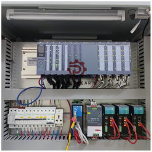
The system utilizes Siemens PLCs for local control and Advantech industrial PCs with InTouch SCADA for visualization.

  • 🌡 The system displays pressure and temperature parameters both locally and on DCS screens.
  • 🔄 Redundant communication interfaces ensure seamless integration with plant-wide networks.

🎯 Core Functional Requirements

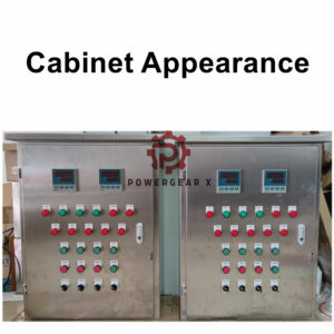
  • 🖥 Local control panels provide pressure/temperature displays and allow operators to adjust setpoints.
  • 📈 Historical temperature data is stored for quality audits and compliance.
  • 🛢 Dual oil pumps in lubrication stations enable automatic fault switching, ensuring uninterrupted operation.
  • 🚨 Differential pressure switches trigger alarms and mill shutdowns during abnormal conditions.

🛡 Safety and Interlocking Logic

  • ⚠️ Oil pressure indicators & differential pressure alarms prevent equipment damage.
  • 🔌 The PLC implements interlock trip logic, automatically halting operations during critical faults.
  • 🌍 Remote communication interfaces support centralized monitoring via Modbus/TCP protocols.

🚀 Operational Advantages

  • Real-time DCS visualization reduces manual inspections.
  • Automated pump switching minimizes downtime and enhances reliability.
  • Historical trend analysis supports predictive maintenance strategies.
  • Standardized protocols simplify third-party system integration.

🔮 Future Scalability

📡 Modular design supports additional sensors or processing lines.
☁️ Cloud connectivity could enhance remote diagnostics and data analytics.
🤖 Machine learning algorithms may be implemented to optimize grinding efficiency in later phases.

If you are looking for DCS integration system, please feel free to Powergear X Automation Limited.

Understanding Bently Nevada Proximity Sensors

Understanding Bently Nevada Proximity Sensors

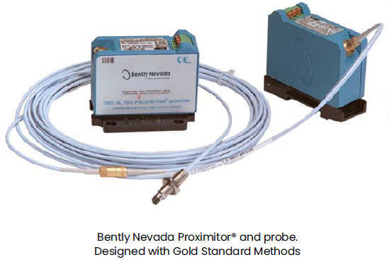
Bently Nevada proximity sensors are indispensable tools in industrial automation. This article delves into the operational principles, diverse applications, and significant advantages of these sensors. Gain a comprehensive understanding of why these sensors are a preferred choice for many industrial processes.

Back to Top
Product has been added to your cart