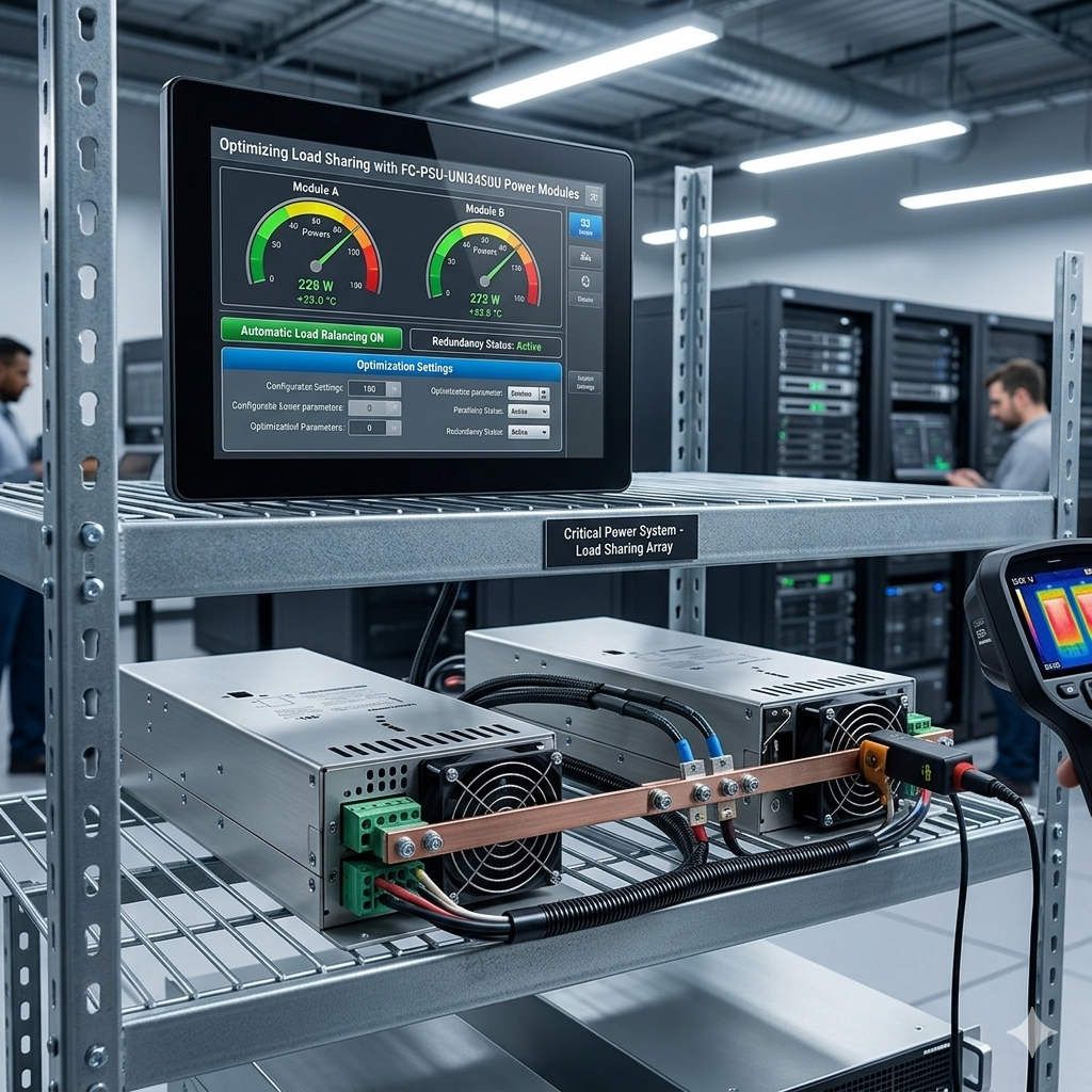
Optimizing Load Sharing with FC-PSU-UNI2450U Power Modules
Optimizing Reliability via FC-PSU-UNI2450U Parallel Power Architecture
Modern industrial plants require high-capacity DC power that stays operational 24/7. While paralleling multiple FC-PSU-UNI2450U modules increases total output, the real challenge lies in balanced current distribution. Uneven loads force a single module to work at peak capacity while others remain idle. This imbalance accelerates thermal stress and degrades critical internal components like electrolytic capacitors. Consequently, systems without proper balancing face unexpected shutdowns during transient voltage spikes in PLC or DCS environments.
Optimizing Load Sharing with FC-PSU-UNI2450U Power Modules
Active Current Sharing vs. Passive Matching
The FC-PSU-UNI2450U excels because it utilizes active current-sharing control circuitry. Unlike passive systems that rely on voltage matching, active control maintains precision during dynamic load shifts. In passive setups, a minor deviation of 50mV can cause significant current hogging. This lead module often experiences rapid temperature rises and premature failure. Therefore, active balancing is essential for remote I/O racks and Honeywell controllers, especially when ambient temperatures exceed 40°C.
Addressing Cable Impedance in Multi-Module Arrays
Hidden resistance in wiring often disrupts even the best power configurations. Identical power supplies may still show a 5% to 8% current imbalance due to inconsistent cable lengths. To mitigate this, engineers should use identical conductor cross-sections and star-distribution topologies. Moreover, avoiding mixed copper and aluminum terminals prevents oxidation-related resistance. Following IEC 60364 guidelines ensures that voltage drops remain within limits during peak startup currents in refinery MCC cabinets.
Thermal Management and System Derating
Total system capacity does not always scale linearly when adding more modules. Enclosure airflow and ambient heat dictate the actual sustainable output. For instance, two 50A modules might not safely deliver a continuous 100A in a sealed cabinet. We recommend maintaining at least 50mm of vertical ventilation clearance. Furthermore, separate exhaust paths prevent hot-air recirculation. Thermal imaging during commissioning helps verify that each module in the parallel group dissipates heat evenly.
Advanced Installation and Surge Protection Strategies
Reliability in oil and gas or water treatment facilities requires robust protection. External Surge Protection Devices (SPD) are vital for both AC inputs and DC outputs. Without coordinated Type II SPDs, transient events can permanently damage rectifier stages. Additionally, we advise against daisy-chaining outputs. A common DC busbar minimizes branch impedance differences. Always verify that ground resistance stays below plant engineering limits to reduce transient impedance during faults.
Selection Logic: Redundancy vs. Maximum Capacity
Choosing the right number of FC-PSU-UNI2450U modules depends on your specific uptime requirements. In high-availability DCS environments, N+1 redundancy is the gold standard. This setup ensures that if one module fails, the remaining units carry the full load without interruption. However, mixing different hardware revisions is generally discouraged. Always validate mixed-generation operation through on-site load testing to prevent circulating currents and chronic overload alarms.
Expert Insights from Powergear X Automation Limited
At Powergear X Automation Limited, we observe that the transition to smarter, active-sharing modules marks a shift toward predictive maintenance. Traditional power supplies were “fit and forget,” but the FC-PSU-UNI2450U allows for better integration into modern diagnostic frameworks. We believe that focusing on thermal symmetry today prevents costly downtime tomorrow. For more technical specifications or procurement support, visit our official site at Powergear X Automation Limited.
Industrial Solution Scenarios
- Petrochemical Plants: Ensuring 24/7 stability for redundant Honeywell Safety Manager systems.
- Offshore Platforms: Utilizing thermal derating strategies to maintain power in high-salt, high-heat environments.
- Pharmaceutical Lines: Implementing N+1 architecture to prevent batch loss during power module maintenance.
Technical Summary Checklist
- ✅ Active Balancing: Precision current sharing for dynamic PLC/DCS loads.
- ⚙️ Wiring Topology: Use star-topology to equalize branch impedance.
- 🔧 Protection: Type II SPD integration for remote or outdoor field stations.
- 🌬️ Airflow: Mandatory 50mm vertical clearance for natural convection.
- 📏 Validation: Commissioning verification with ±10% current deviation limits.
Frequently Asked Questions (FAQ)
1. Why does one module in my parallel set run significantly hotter than the others?
This is typically caused by unequal branch resistance rather than a PSU defect. If the cable to one module is shorter or the terminal is tighter, it offers a path of least resistance, forcing that module to carry more current. Checking terminal torque and cable lengths usually resolves this based on our field experience.
2. Can I mix the FC-PSU-UNI2450U with older legacy power modules?
While theoretically possible if voltages match, it is risky. Older generations often lack active sharing logic. The newer module might “fight” the older one, leading to circulating currents. We recommend a full system upgrade or rigorous load-bank testing before permanent integration.
3. What is the most common failure point in parallel power installations?
Beyond thermal exhaustion, terminal oxidation is a frequent culprit. In humid or corrosive industrial environments, high-resistance connections at the DC busbar create imbalances that trigger nuisance alarms or premature capacitor aging. Regular infrared thermography is the best preventative measure.