
Over 50,000 hot-selling automation module components.

GE IS200JPDHG1A Troubleshooting: False Total Failure Alarms

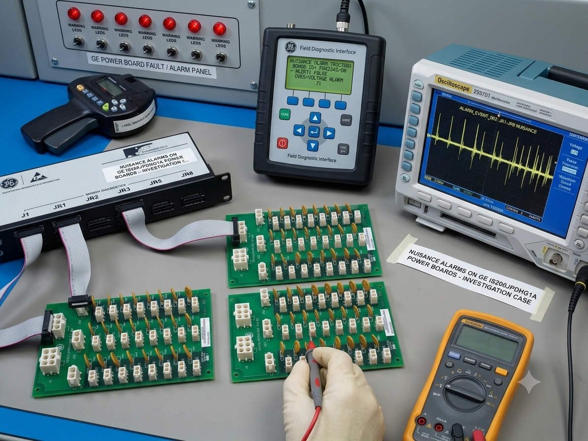
Can Monitoring Circuit Drift on the GE IS200JPDHG1A Cause False System Trips?

In high-availability industrial automation, faulty diagnostic feedback can prove as damaging as actual physical hardware failures. The GE IS200JPDHG1A Power Distribution Board serves as the central power backbone within EX2100 excitation systems. Beyond distributing vital DC voltage rails, this board actively monitors subsystem health metrics. However, an isolated internal failure within its internal sensing loop can trick the main controller. Consequently, the DCS may generate an unwarranted “Power System Total Failure” critical alarm message.
The Functional Architecture of Power Supervision Circuitry

The IS200JPDHG1A integrates an intricate network of analog voltage dividers, operational amplifiers, and status signal comparators. These components constantly read feedback parameters across multiple incoming power feeds. After processing, the hardware forwards real-time status packets straight to the core turbine control systems. This architecture ensures that the controller can instantly identify sagging power lines. Therefore, the processing brain can protect downstream electronics before an absolute brownout disrupts plant operations.

How Internal Board Anomalies Generate Ghost Alarms

Component degradation can mimic a severe electrical blackout within the power distribution array. Over time, analog sensing channels can experience thermal resistance drift or comparator latch-up malfunctions. When this occurs, the diagnostic circuitry reports low or absent voltage despite a perfectly healthy DC bus. If the system lacks redundant cross-checking paths, a single sensor failure may trigger an immediate emergency trip. This false alarm unnecessarily isolates the entire generator excitation unit from the power grid.

Industry research indicates that up to 30% of power supply diagnostic alarms stem from feedback path errors. Pin oxidation on heavy backplane connectors can similarly attenuate the weak low-voltage telemetry signals. Moreover, old firmware configurations may misinterpret a single channel fault as an absolute power failure. Engineers must cross-reference actual physical bus bars before approving extensive control system module swaps.

Noise Immunity Vulnerabilities in Heavy Factory Automation

Turbine rooms host heavy electromagnetic fields generated by excitation transformers and massive variable frequency drives. The low-voltage supervisory lines on the IS200JPDHG1A remain susceptible to high-frequency induced noise. If cabinet grounding terminals loosen, common-mode noise can override the true analog feedback measurements. This electrical interference distorts waveform edges, leading to intermittent channel mismatch errors. Maintaining excellent shield continuity remains mandatory to protect signal tracking accuracy.

Evaluating Backward Compatibility and Selection Differences

Replacing an older power supervisor requires careful checking of part number suffix variations. While the base IS200JPDHG1A model handles standard distribution tasks, physical revision layers alter connector arrangements. Certain sub-versions feature specialized trace impedances designed to handle modern high-speed noise filtering tasks. Attempting to install an unverified board revision can introduce unintended parameter reading offsets. To avoid project delays, procure components from certified distributors like Powergear X Automation Limited.

Step-by-Step Diagnostic Verification Protocols

  • Physical Bus Measurement: Measure the true incoming DC control voltage directly using a calibrated digital multimeter.
  • ⚙️ Connector Inspection: Unplug and re-seat all communication cables while checking for immediate thermal pin discoloration.
  • 🔧 Chronological Log Analysis: Examine the ToolboxST event sequence to trace if channel faults preceded the total blackout alarm.

Strategic Maintenance Perspectives from Powergear X Automation Limited

At Powergear X Automation Limited, we emphasize that automatic hardware swapping often increases overall troubleshooting costs. When a total power failure indicator arises, blindly replacing the distribution block skips root-cause verification. Many issues resolve after cleaning oxidized edge contacts with manufacturer-approved chemical solvents. We suggest tracking sensing calibration trends during standard annual system turnarounds. To explore our comprehensive database of genuine GE components, visit our store at https://www.powergearx.com/.

Real-World Application Scenarios

During a baseline commissioning phase at a combined-cycle power station, operators reported a sudden, unexplained total power alarm. Physical tests confirmed that the main 125VDC auxiliary battery supply remained fully energized. Further analysis traced the error to an open-circuit feedback trace on the distribution board. Replacing the damaged module restored correct telemetry reporting, allowing the plant to achieve full production output without further delay.

Frequently Asked Questions (FAQ)

1. Why does a minor analog drift escalate to a complete total power system shutdown message?
If the controller code uses an unweighted “AND” condition across sensing channels, a single dead input simulates a total voltage loss. Updating your I/O block parameters to utilize voting logic solves this vulnerability.

2. Can I test the internal comparator circuitry of this board while the system runs online?
Online manual circuit tracing is highly discouraged due to short-circuit risks near the main power buses. Confine deep component-level validation to a static test bench during standard outage schedules.

3. How do I differentiate between a real input supply failure and a board-level telemetry fault?
A genuine supply failure simultaneously alters parallel monitoring systems, such as your main upstream switchgear breakers. If only the specific board reports zero volts while other metrics remain unchanged, suspect a telemetry issue.
GE IS200EPDMG1BAA Power Board Surge Protection Guide

Replace GE IS200EPDMG1BAA MOVs After Lightning Surges?

Should You Replace the MOV on the GE IS200EPDMG1BAA Board After a Lightning Strike?

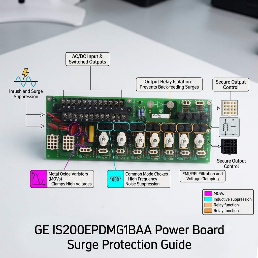
In high-availability heavy industries, unseen electronic degradation poses a severe threat to operational continuity. The GE IS200EPDMG1BAA Power Distribution Board serves as a foundational power conditioning component. It supports critical Mark VI, Mark VIe, and EX2100 control systems. A core element of its protective layout is the Metal Oxide Varistor (MOV). However, field technicians often wonder if they must replace an internally stressed MOV that looks perfectly fine. This article explores the hidden degradation mechanisms of surge protection in critical infrastructure.

GE IS200EPDMG1BAA Power Board Surge Protection Guide

GE IS200EPDMG1BAA Power Board Surge Protection Guide

The Functional Role of the IS200EPDMG1BAA in Factory Automation

The IS200EPDMG1BAA board safely allocates control power across complex modern turbine and excitation cabinets. It ensures steady DC and AC voltage delivery to sensitive I/O packs and processing cores. Consequently, any failure on this board can interrupt communication networks or drop key field outputs. The integrated MOVs act as the primary defense mechanism against incoming voltage spikes. Therefore, the board absorbs high-energy disturbances before they reach microprocessors downstream.

Technical Principles of Cumulative MOV Aging and Clamping Deviations

An MOV does not always clear a fault by exploding or scorching its exterior shell. Instead, the internal zinc oxide microstructure degrades incrementally with each absorbed surge event. High-transient lightning currents create microscopic conduction paths inside the component matrix. As a result, the device experiences an immediate increase in baseline leakage currents. This hidden wear lowers the original clamping voltage threshold over time without showing any visual clues. A compromised component will ultimately fail to protect adjacent circuits during subsequent overvoltage transients.

Industry research from the IEEE Standards Association indicates that over 30% of surge module failures involve cumulative silent degradation. When clamping voltage stability drifts, downstream insulation experiences much higher electrical stress during power fluctuations. This continuous strain shortens the life expectancy of connected power supply modules. Furthermore, increased leakage current generates internal localized heating on the circuit board. This thermal stress can eventually provoke random controller resets and unexplained diagnostic alarms.

Application Scenarios and Selection Criteria for Advanced Power Boards

Power distribution reliability remains paramount in oil & gas facilities, chemical plants, and remote compressor skids. These exposed environments frequently experience direct lightning activity and severe switching transients. Choosing the IS200EPDMG1BAA ensures that your control network complies with strict industrial transient safety margins. However, sourcing replacement components requires thorough validation of your specific cabinet layout. Engineers must carefully match the product revision suffix to ensure absolute mechanical and electrical compatibility.

Replacing a legacy power distribution board involves verifying firmware boundaries and matching power supply connections. Some earlier module iterations lack the exact fuse ratings found on the “1BAA” version. Therefore, unverified substitution can create protection gaps or cause premature branch trips during normal operations. For accurate selection data and genuine replacement parts, procurement specialists frequently collaborate with Powergear X Automation Limited.

Field Maintenance Rules for High-Risk Surge Infrastructure

  • Electrical Verification: Perform leakage current and insulation testing rather than relying solely on visual inspection.
  • ⚙️ Upstream Inspection: Check primary surge protective devices and cabinet grounding paths during every turnaround.
  • 🔧 Proactive Replacement: Swap out the power board if nearby lightning trips external breakers or corrupts baseline data.

Strategic Insights from Powergear X Automation Limited

At Powergear X Automation Limited, we prioritize structural reliability over simple visual diagnostics. In high-stakes industrial automation, treating surge protection as a disposable asset is the safest operational approach. Proactive replacement of a potentially weakened board prevents catastrophic downtime that can easily cost thousands of dollars per minute. To view our full inventory of verified control components, explore our solutions at https://www.powergearx.com/.

Real-World Solutions for Turbine Control Rooms

In a coastal power station, a severe storm induced a major voltage surge across the main excitation busbar. The IS200EPDMG1BAA board continued operating normally, and visual checks revealed no physical damage. However, the maintenance team followed proactive protocols and replaced the distribution card during a brief outage. Subsequent bench tests proved the original MOV had lost 40% of its surge capacity. This preventive step saved the plant from a total turbine trip during a secondary storm two weeks later.

Frequently Asked Questions (FAQ)

1. How can a field technician test an MOV on the power board without specialized lab equipment?
You can use a high-voltage insulation tester to check the varistor voltage at a specified DC leakage current. If the measured voltage deviates significantly from the original manufacturer specifications, the internal structure is degraded.

2. Can I replace just the individual degraded MOV on the board instead of buying a new card?
While physically possible, component-level soldering on multilayer industrial boards is not recommended for live field environments. It voids certifications, alters trace impedance, and may introduce hidden micro-cracks into nearby paths.

3. Does the system generate a specific diagnostic alarm when the MOV begins to wear out?
Standard systems do not monitor individual MOV degradation paths directly. Instead, you might see secondary symptoms like unstable branch power supply logs or random I/O faults caused by unmitigated transient noise.

Back to Top
Product has been added to your cart