Over 50,000 hot-selling automation module components.
Allen-Bradley 1769-L16ER-BB1B SD Card Recovery Guide

Allen-Bradley 1769-L16ER-BB1B SD Card Recovery Guide

Optimizing Industrial Uptime with the Allen-Bradley 1769-L16ER-BB1B SD Card Functionality

The Strategic Role of Removable Storage in Modern PLC Systems

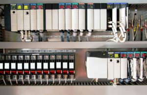
The Allen-Bradley 1769-L16ER-BB1B serves as a cornerstone for compact, high-performance automation. While its dual Ethernet ports and integrated I/O attract many engineers, the Secure Digital (SD) card slot offers a critical layer of operational resilience. In modern factory environments, this feature transforms the controller from a static device into a dynamic, self-restoring system. It allows teams to deploy programs without a dedicated engineering laptop, significantly lowering technical barriers during emergency recoveries.

Allen-Bradley 1769-L16ER-BB1B SD Card Recovery Guide

Mastering the Boot Sequence and Image Loading Mechanics

The 1769-L16ER-BB1B utilizes a sophisticated boot sequence controlled via firmware settings. Engineers can configure the “Load Image” parameter to trigger automatically upon power-up. Consequently, the controller detects the SD card, verifies the image integrity, and overwrites the internal volatile memory. This deterministic behavior proves invaluable for Original Equipment Manufacturers (OEMs). It ensures that every machine in a global fleet runs identical, validated code without manual intervention.

Technical Deep Dive: Memory Architecture and Firmware Alignment

A successful deployment depends on the harmony between the hardware’s internal memory and the SD backup. The 1769-L16ER-BB1B stores active logic in internal non-volatile memory, yet the SD card acts as the “Master Gold Image.” According to industry insights, the trend toward modular automation requires strict versioning. If the controller firmware version mismatches the SD image, the load process will fail. Therefore, engineers must synchronize firmware updates with their physical SD backups to avoid costly initialization faults.

Step-by-Step Manual Force-Loading Procedure

When a controller becomes corrupted or requires a complete reset, a manual force-load is the most reliable recovery path. Follow these precise steps to ensure success:

  • Power down the 1769-L16ER-BB1B unit completely.
  • Insert a FAT32-formatted SD card containing the valid Studio 5000 image.
  • Press and hold the physical reset button located on the front panel.
  • Apply power to the controller while maintaining pressure on the button.
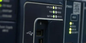
  • Wait for the OK LED to flash red/green, signaling the load mode.
  • Release the button to allow the automatic transfer to conclude.

Powergear X Insight: Timing is everything. Releasing the reset button too early often defaults to a standard boot, bypassing the SD image entirely.

Ensuring Compliance and Reliability in Regulated Industries

In sectors governed by FDA 21 CFR Part 11 or GAMP 5, traceability is non-negotiable. The SD card provides a physical “Lock-and-Key” for program management. By physically controlling access to the SD cards, plant managers can prevent unauthorized logic changes. Furthermore, using industrial-grade media reduces the risk of file corruption caused by electrical noise or high-vibration environments typical in packaging and stamping lines.

Selection Criteria and Hardware Distinctions

Choosing the 1769-L16ER-BB1B involves understanding its specific constraints compared to larger 1769-L3 series models. While the L16ER is cost-effective for small-scale applications, its memory limits make the SD card even more vital for recovery.

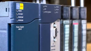
  • Capacity: Supports up to 2GB or 1GB industrial SD cards from Rockwell.
  • Connectivity: Features integrated 16 DC inputs and 16 DC outputs.
  • Performance: Designed for up to 4 EtherNet/IP nodes, ideal for standalone machines.
  • Compatibility: Unlike older CompactLogix models, this unit requires Studio 5000 Logix Designer for image creation.

Expert Analysis from Powergear X Automation Limited

At Powergear X Automation Limited, we observe a growing shift toward “Laptop-Free Maintenance.” The 1769-L16ER-BB1B exemplifies this trend by empowering floor technicians to handle complex swaps. However, we recommend a strict auditing process for SD images. As industrial automation moves toward more integrated DCS environments, the physical SD card remains the most robust “Plan B” against network failures or memory loss.

Application Scenarios and Solutions

  • Water Treatment Facilities: Remote sites often lack on-site engineering support; SD recovery ensures local operators can restore service instantly.
  • Standardized Packaging Lines: OEMs can ship pre-loaded SD cards to global customers for seamless field upgrades.
  • High-Vibration Manufacturing: Using seated, industrial-grade cards prevents data loss during heavy mechanical operation.

Technical Best Practices Checklist

  • ✅ Only use Rockwell-certified industrial SD cards for long-term data retention.
  • ✅ Periodically verify the “Store on Power Down” settings in Studio 5000.
  • ✅ Protect the controller with proper grounding to prevent SD file system corruption.
  • ✅ Document firmware versions on the physical label of the SD card for quick reference.

Frequently Asked Questions (FAQ)

Q: Can I use a standard commercial SD card from a local electronics store?
While a standard card might work temporarily, we strongly advise against it. Industrial-grade cards use SLC (Single-Level Cell) flash, which handles extreme temperatures and higher write cycles, preventing failure in hot control panels.

Q: What happens if the ‘OK’ LED stays solid red during a load?
A solid red OK LED typically indicates a major non-recoverable fault. This often occurs if the firmware on the SD card is incompatible with the controller hardware revision. You must use a laptop to flash the correct firmware before the SD load will succeed.

Q: How do I prevent the SD card from being overwritten accidentally?
Within the Studio 5000 “Non-Volatile Memory” tab, you can set the Load Image attribute to “On Corrupt Memory” or “User Initiated” instead of “On Power Up.” This prevents the controller from overwriting its internal memory unless a specific fault occurs.

For more technical guides and high-reliability automation components, visit the official Powergear X Automation Limited website to explore our full inventory.

Troubleshooting AB PLC Non-Recoverable Faults: A Field Guide

How to Export & Analyze Allen-Bradley Non-Recoverable Major Faults

Troubleshooting Allen-Bradley Non-Recoverable Major Faults: A Diagnostic Guide

The Critical Role of the PLC Fault Log

In industrial automation, a “Non-Recoverable Major Fault” signal usually means production has already halted. Consequently, the controller’s fault log becomes your most valuable diagnostic asset. Engineers must export this data to distinguish between firmware corruption and hardware failure. Moreover, accurate logs support Root Cause Analysis (RCA) and help meet regulatory standards like FDA 21 CFR Part 11. Without this data, maintenance teams often waste hours guessing the cause of unplanned downtime.

Troubleshooting AB PLC Non-Recoverable Faults: A Field Guide

Understanding Fault Types and Code Granularity

Allen-Bradley systems, including ControlLogix and CompactLogix, categorize errors by Type, Code, and Extended Code. These specifics are vital because a non-recoverable fault often indicates a deep hardware or firmware conflict. For example, my field experience shows that electrostatic discharge (ESD) often triggers memory corruption. While front-panel LEDs might show a generic red light, the exported log reveals the specific memory address failure. Therefore, granular data is essential for preventing repeat occurrences in high-stakes factory automation environments.

Protecting Data in Volatile Controller Memory

Controllers store fault logs in volatile memory, which clears if the system loses power. To prevent data loss, I highly recommend installing a non-volatile memory module, such as the 1784-SD2. This hardware ensures the fault history survives a power cycle or a complete CPU reset. In continuous-process industries, losing this history can extend the Mean Time to Repair (MTTR) significantly. Furthermore, a permanent record is necessary for compliance audits in pharmaceutical or chemical plants.

Navigating Studio 5000 Compatibility Issues

Exporting a detailed fault log requires the correct version of Studio 5000 Logix Designer. If you use a mismatched software version, you might go online but miss critical “Extended Code” details. Always ensure your workstation software version matches or exceeds the controller’s major firmware revision. In addition, maintaining a multi-version installation on your engineering laptop prevents “diagnostic blind spots” when working with legacy control systems.

A Field-Proven Workflow for Exporting Logs

When a fault occurs, follow a disciplined technical process to ensure you capture every detail. Do not rush to clear the fault immediately, as this erases the evidence needed for a permanent fix.

  1. Establish a secure connection using Studio 5000 Logix Designer.
  2. Navigate to Controller Properties and select the Major Faults tab.
  3. Record the specific Fault Type, Code, and Extended Code.
  4. Select Tools then Save Project with Fault Information.
  5. Capture screenshots of the Diagnostics tab for additional context.

Practical Maintenance Insights from the Factory Floor

In high-EMI (Electromagnetic Interference) environments, “Non-Recoverable” faults often stem from poor grounding rather than a defective CPU. Before replacing expensive hardware, I suggest inspecting surge suppression and backplane integrity. If a controller faults repeatedly after power cycles, the power supply is the most likely culprit. Powergear X Automation experts often find that replacing the power supply solves 30% of persistent non-recoverable errors without needing a new processor.

The Powergear X Automation Perspective on Reliability

At Powergear X Automation, we believe that data-driven maintenance is the backbone of modern industrial reliability. We often see teams replace CPUs prematurely due to a lack of diagnostic clarity. By integrating non-volatile memory and robust firmware version control, you create a more resilient control system. If you are looking to upgrade your legacy systems or need high-quality replacement modules, our team provides the technical expertise to ensure your hardware choices match your operational needs.

Application Scenario: Resolving Intermittent Backplane Failures

In a large-scale pharmaceutical packaging line, a ControlLogix CPU reported a non-recoverable fault every 48 hours. By exporting the fault log, the engineering team identified “Type 01 Code 01” errors, which pointed to backplane communication issues. Instead of replacing the CPU, they discovered a loose 1756-A10 chassis mounting bolt causing intermittent grounding issues. This discovery saved the plant over $10,000 in unnecessary hardware costs.

Frequently Asked Questions (FAQ)

1. Does a non-recoverable fault always require a hardware replacement?
No, it does not. Statistics suggest nearly 50% of these faults result from power quality issues or firmware glitches. Always analyze the “Extended Fault Code” before purchasing new components.

2. What is the most common mistake made during an emergency fault event?
The most common error is clearing the fault or cycling power before exporting the log. This action permanently deletes the diagnostic breadcrumbs needed for a true root cause analysis.

3. How can I ensure my fault logs are preserved during a total power failure?
You should equip every mission-critical Allen-Bradley PLC with an industrial-grade SD card (non-volatile memory). Configure the controller to store “Project and Fault” data to the card on every major fault event.

Mastering RX3i Diagnostics Troubleshooting

Mastering RX3i Diagnostics & Troubleshooting: How to Slash Mean-Time-To-Repair (MTTR)

Introduction

As an engineer and operations manager with years of experience in industrial control, I know how critical it is to minimize downtime. The RX3i PAC Systems are robust, but even the best systems can encounter issues. The real challenge isn’t preventing problems entirely—it’s fixing them fast. This guide will share my insights on how to slash your Mean-Time-To-Repair (MTTR) when working with RX3i, turning potential headaches into quick fixes.

Mastering RX3i Diagnostics Troubleshooting

Understanding Your RX3i System Inside Out

Before you can troubleshoot, you need to deeply understand your system. This goes beyond just knowing what each module does. It means understanding the interconnections, the expected behavior under normal operation, and the specific failure modes unique to your application. I’ve seen many situations where a lack of foundational knowledge led to hours of wasted troubleshooting.

Leveraging Built-in Diagnostic Tools

The RX3i offers powerful built-in diagnostics. Don’t just scan for faults; understand what each fault code means.

  • PACSystems Machine Edition (PME): This is your primary window into the RX3i. Get familiar with the Reference View and I/O Navigator.
  • Diagnostic Log: The PLC’s diagnostic log is invaluable. It records events and faults with timestamps.
  • Force and Disable: Use these functions cautiously, but master them for testing.

Mastering RX3i Diagnostics Troubleshooting

Strategic Troubleshooting Approaches

I advocate for a systematic approach rather than random trial-and-error.

  • Define the Problem Clearly: What exactly is happening? When did it start? What changed?
  • Isolate the Issue: Is it hardware or software? Input or output? Specific module or entire rack?
  • Check the Simplest Things First: Is the power on? Are cables properly seated? Is a fuse blown?
  • One Change at a Time: When you’re making adjustments, change only one thing and then re-test.
  • Documentation is Key: Keep up-to-date schematics, logic diagrams, and maintenance logs.

My Unique Insights: Beyond the Manual

  • The “Hunch” Factor: While systematic, don’t dismiss your gut feeling.
  • Network Diagnostics as a First Step: In modern systems, network issues often mimic PLC faults.
  • The Power of Peer Collaboration: Don’t be afraid to ask for help.
  • Preventive Diagnostics: Don’t wait for a failure. Monitor key parameters, track module health, and perform routine checks.

Why Slash MTTR? It’s About More Than Just Repair Time

Reducing MTTR isn’t just about how quickly you fix a machine. It impacts overall productivity, operational costs, and even safety. Faster repairs mean less lost production, lower labor costs for maintenance, and reduced risk of secondary damage or safety incidents. It directly contributes to your bottom line.

Conclusion: Investing in Knowledge Pays Off

Mastering RX3i diagnostics and troubleshooting is an ongoing process. It requires a blend of technical knowledge, systematic thinking, and practical experience. By understanding your system, leveraging its diagnostic capabilities, adopting strategic troubleshooting methods, and applying the insights shared here, you can significantly reduce your MTTR and keep your operations running smoothly.

Mastering RX3i Diagnostics Troubleshooting

Ready to optimize your RX3i systems and minimize downtime? Explore our range of high-quality RX3i products and solutions designed to enhance your industrial automation.

Click here to see PowergearX Automation Limited’s RX3i products!

ModelTitleLink
IC695CPE310GE Fanuc RX3i Central Processing UnitLearn More
IC695CPK330GE Fanuc RX3i Central Processing UnitLearn More
IC695CPK330GE Fanuc RX3i PACSystem CPULearn More
IC695ALG106PACSystems RX3i Analog Input ModuleLearn More
Back to Top
Product has been added to your cart