
Over 50,000 hot-selling automation module components.
Measure Switching Noise on GE IS2020RKPSG3A Module

Measure Switching Noise on GE IS2020RKPSG3A Module

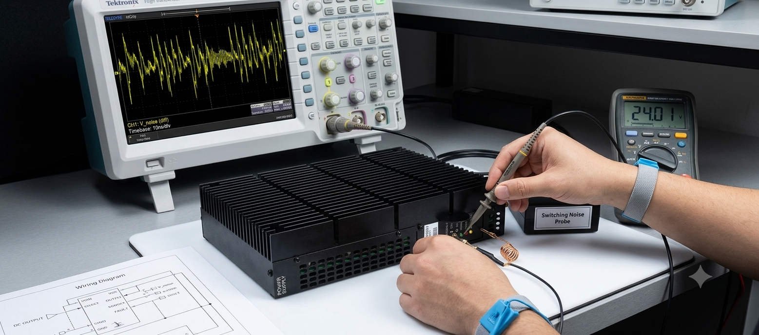
Analyzing High-Frequency Switching Noise on the GE IS2020RKPSG3A Power Supply Bus

In heavy industrial automation, clean low-voltage DC power safeguards processor integrity. The GE IS2020RKPSG3A power supply module delivers critical 5VDC power to EX2100 excitation systems and Mark VI control racks. However, a standard digital multimeter cannot capture high-frequency switching anomalies on the bus. This technical article covers the exact oscilloscope methods required to analyze dangerous ripple voltages. As a result, engineers can protect vital control networks from unexpected trips.
Measure Switching Noise on GE IS2020RKPSG3A Module

Measure Switching Noise on GE IS2020RKPSG3A Module

The Core Function and Architecture of the Power Module

The IS2020RKPSG3A utilizes a high-efficiency switch-mode power conversion architecture. It regulates voltage for downstream processing boards and critical communication interfaces. In addition, the internal circuitry isolates the control logic from heavy grid surges. This regulation keeps processing environments functional during severe load fluctuations. However, the native switching frequency inevitably introduces high-frequency ripple components onto the distribution lines.

Operational Principles of Oscilloscope Ripple Diagnostics

Detecting power anomalies requires proper instrument bandwidth selection and specific input coupling. Maintenance teams must utilize an oscilloscope with a minimum bandwidth of 100 MHz. Furthermore, engineers should select AC coupling to strip away the dominant 5VDC component. This setting allows the instrument to isolate the underlying millivolt-level noise. Consequently, you can observe high-frequency spikes that cause CPU watchdog resets and network dropouts.

The Critical Nature of Correct Probe Grounding

Standard oscilloscope probes often include long ground leads with alligator clips. However, these long wires act as antennas in noisy power generation environments. They capture stray electromagnetic interference from surrounding high-current bus ducts. To avoid false readings, technicians must utilize a short spring ground accessory. This practice restricts the ground loop area to under two centimeters. Therefore, it ensures that observed waveform ringing stems from the power supply rather than external induction.

Incorrect grounding methods can artificially inflate peak-to-peak voltage readings by several hundred percent. This inflation frequently leads to the premature replacement of perfectly healthy modules. Experienced engineers always measure ripple directly across the distribution terminal blocks. This strategic placement provides an accurate view of the voltage quality reaching the control systems.

Evaluating Compatibility and Module Selection Variations

When executing system updates, procurement officers must review original factory hardware revisions. The IS2020RKPSG3A features specific mechanical connector footprints and thermal properties. Older power supply variations may look identical but lack advanced internal noise filtering. In addition, backplane interface configurations can vary slightly across different controller generations. Relying on verified suppliers like Powergear X Automation Limited prevents costly installation compatibility errors.

Online Measurement and Calibration Benchmarks

  • Instrument Setup: Activate the 20 MHz bandwidth limiter to eliminate irrelevant high-frequency ambient radiation.
  • ⚙️ Baseline Profiling: Record bus waveforms during steady-state operation and major process load transitions.
  • 🔧 Network Inspection: Verify terminal torque values and check downstream filtering capacitors for leakage.

Expert Market Commentary from Powergear X Automation Limited

At Powergear X Automation Limited, we monitor component lifecycle patterns across major power plants globally. We notice that many power supply faults trace back to aging capacitors on adjacent I/O modules. As these capacitors degrade, they no longer buffer the 5VDC bus effectively. Therefore, we highly recommend performing preventative oscilloscope health checks annually. To find certified replacement components and optimize your factory automation assets, visit our portal at https://www.powergearx.com/.

Industrial Application Scenarios

In offshore gas extraction facilities, turbine control stability directly influences production metrics. The IS2020RKPSG3A maintains steady core voltages for the central processors. By implementing routine ripple tracking, maintenance crews can detect supply degradation months before a terminal blowout occurs. This proactive strategy ensures continuous operation of the DCS during severe ambient temperature changes.

Frequently Asked Questions (FAQ)

1. What peak-to-peak millivolt threshold indicates a need to replace the module?
While minor ripple is normal, high-frequency switching noise exceeding 50mVpp warrants close observation. If spikes regularly surpass 100mVpp during load transitions, replace the unit to protect downstream processors.

2. Can I replace the module while the turbine control system is active?
Live replacement depends on your rack redundancy configuration. In non-redundant simplex setups, pulling the module causes an immediate controller crash. Always confirm system redundancy status before attempting live servicing.

3. Why does the 5VDC bus show high noise when the power module passes bench tests?
This discrepancy usually indicates external electromagnetic interference. Poor cabinet bonding or missing cable shields allow noise from neighboring VFD equipment to induce voltage spikes onto the DC distribution lines.

Fix GE IS200ERDDH1ABA Black Screen Fault With Flashing LED

Fix GE IS200ERDDH1ABA Black Screen Fault With Flashing LED

Solving the GE IS200ERDDH1ABA Black Screen Anomaly With Flashing Communication LEDs

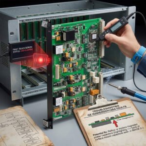
In heavy-duty industrial automation, visual feedback remains essential for safe control operations. Field engineers using GE Mark VI and Mark VIe systems often face a confusing diagnostic scenario. The IS200ERDDH1ABA remote display board initializes with a completely black screen. However, the onboard communication LED continues to blink normally. This symptom indicates that lower-level data bus hardware remains functional. Nevertheless, the independent video rendering or backlight path has failed entirely.

Fix GE IS200ERDDH1ABA Black Screen Fault With Flashing LED

Fix GE IS200ERDDH1ABA Black Screen Fault With Flashing LED

The Operational Function of the Remote Display Module

The IS200ERDDH1ABA provides critical real-time status data directly from the turbine core. It translates complex internal data streams into actionable graphics for on-site maintenance crews. In power generation and petrochemical sectors, this interface reduces dependency on central control rooms. The module features integrated serial transceivers and dedicated memory chips to manage local screen refreshes. Consequently, it maintains local monitoring capabilities even during heavy DCS network loading events.

The Principle of Dual Path Initialization Failures

Understanding this fault requires analyzing the separate power supply routing on the processor board. The communication microprocessor operates on low-voltage logic thresholds, typically around 3.3VDC. Therefore, it can initialize and flash its status LED during marginal voltage sags. In contrast, the liquid crystal array and backlight driver demand stable, higher-tolerance power rails. If the incoming power supply degrades, the communication circuits boot up while the screen remains dead.

Investigating Firmware Incompatibility and Graphic Renders

A blinking indicator proves that the display board exchanges data packets with the controller backplane. However, successful data receipt does not guarantee that the local graphics processor can render images. During phased plant upgrades, engineers often install newer controller code while leaving legacy display software unchanged. This variation causes a severe firmware handshake mismatch upon system boot-up. The module receives information successfully but cannot map the variables to the older display library.

Mechanical Stress and High-Vibration Environment Risks

Turbine enclosures expose sensitive control systems to continuous mechanical vibrations and intense heat cycles. Over years of service, these forces weaken internal connections between the PCB and the glass panel. High contact resistance frequently develops along the microscopic copper traces of flexible ribbon cables. Moreover, airborne contaminants accelerate oxidation on terminal header pins inside the cabinet. These subtle physical defects can cut off video signals while leaving robust communication lines intact.

A Comprehensive Selection and Procurement Guide

When sourcing replacement components, procurement managers must match exact suffix variations. The IS200ERDDH1ABA features specific revision characteristics tailored for standard Mark VI configurations. Substituting it with older revisions can introduce physical shape conflicts or terminal layout changes. In addition, ensure the replacement board contains the correct pre-loaded bootloader firmware. Relying on specialized distributors like Powergear X Automation Limited prevents costly engineering delays.

Field Maintenance Routines for Display Interfaces

  • Flashlight Inspection: Shine a bright light at an angle across the black screen to reveal hidden text.
  • ⚙️ Dynamic Voltage Audit: Measure the terminal power rail under full startup load to capture temporary drops.
  • 🔧 Ribbon Seating: Clean header contacts with certified solvent and secure ribbon cables using locking clips.

Industry Commentary from Powergear X Automation Limited

At Powergear X Automation Limited, we emphasize that field symptoms are rarely clear-cut in factory automation. A flashing LED often creates a false sense of security regarding hardware health. We advise technicians to execute cross-swaps with functional matching terminals during planned maintenance outages. This method quickly isolates software bugs from physical hardware component failures. To explore our comprehensive catalog of verified GE modules, check out our site at https://www.powergearx.com/.

Real-World Application Scenarios

During a peak-load startup at a natural gas power facility, a critical turbine display suddenly went dark. While the network interface indicators continued flashing, operators could not confirm auxiliary pump parameters locally. Using a structured diagnostic framework, technicians identified a 500-millivolt drop on the local 24VDC feeder loop. Replacing the worn terminal power supply immediately restored the screen graphics. This approach averted an expensive emergency shutdown sequence.

Frequently Asked Questions (FAQ)

1. What does it mean if faint images are visible under a flashlight during a black-screen event?
This indicates that the graphic logic and communication circuits are functioning perfectly. The failure rests entirely inside the backlight inverter circuit or the high-intensity LED array itself.

2. How do I upgrade the internal display software if the terminal remains completely black?
You must establish a direct serial connection via the dedicated maintenance port using ToolboxST. This bypasses the corrupted primary runtime database and forces a clean firmware overwrite sequence.

3. Can external electrical surges cause this specific flashing-LED black-screen state?
Yes. High-voltage transients often slip past primary cabinet barriers and strike the sensitive analog drivers of the display panel. Meanwhile, the digitally isolated communication transceivers survive the surge unscathed.

Back to Top
Product has been added to your cart