Over 50,000 hot-selling automation module components.
Bently Nevada 190501 Troubleshooting & Repair Guide

How to Fix Common Faults in Bently Nevada Vibration Sensors

Expert Troubleshooting Guide for Bently Nevada 190501 Vibration Sensors

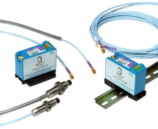
The Bently Nevada 190501 Velomitor is a workhorse of industrial condition monitoring, but harsh environments can challenge its reliability. When vibration data becomes erratic or fails, production and protection systems are compromised. This guide provides systematic diagnostics for common 190501 failures, enabling rapid restoration of accurate machinery health data to your control systems.

Bently Nevada 190501 Troubleshooting & Repair Guide

Systematic Approach to Signal Loss and Zero Output

Complete signal loss manifests as a “dead channel” on the monitor. Begin diagnostics at the sensor and work backward. First, verify the sensor’s coil resistance with a multimeter; a reading outside 500-800 Ω indicates internal failure. Next, check cable continuity and inspect the MIL-C-5015 connector for bent pins or corrosion. Finally, confirm the monitoring channel is configured for “Passive Velocity” input, not IEPE acceleration.

Diagnosing and Eliminating Electrical Noise

Erratic, jumping readings typically stem from electromagnetic interference (EMI) or ground loops. This noise corrupts the low-level velocity signal. To resolve, ensure the sensor cable shield is grounded at the monitor end only. Route cables away from variable frequency drives (VFDs) and power lines. Install ferrite clamps near connectors to suppress high-frequency noise. Verify all junction box connections are tight and free of moisture.

Correcting Signal Drift and Calibration Shift

Gradual signal drift indicates sensor degradation or environmental stress. Compare the sensor’s output with a portable calibrator generating a known 10 Hz, 1 in/s RMS signal. A deviation >10% from the sensor’s stated sensitivity requires investigation. Check for excessive sensor base temperature (>120°C) or thermal cycling, which can permanently alter piezoelectric properties. Document baseline “at-rest” readings for future comparison.

Resolving Persistent False Alarms

False alarms erode trust in protection systems. First, analyze the vibration spectrum. Non-synchronous spikes at 50/60 Hz or harmonics indicate electrical noise, not mechanical fault. If the vibration is real but non-damaging, review alarm setpoints against ISO 10816 standards for the machine type. Structural resonance amplifying casing vibration may require remounting the sensor on a more rigid location or adding damping material to the bracket.

Addressing “Channel Not OK” Monitor Faults

When the monitoring system reports a fault, it’s often a system integration issue. Swap the sensor to a known-good channel to isolate the problem. Measure the input voltage at the monitor terminal; it should match the system specification. Update the monitor module’s firmware if available, as compatibility issues can cause communication dropouts. Inspect the backplane connector for oxidation.

Expert Insight: The 80/20 Rule of Sensor Failures

At Powergear X Automation, we find 80% of suspected sensor failures are actually installation or integration issues. Only 20% require sensor replacement. A common oversight is mounting the sensor on a painted or uneven surface, which creates a low-pass filter effect, attenuating high-frequency bearing fault signals. Always machine the mounting surface flat and clean. Proactive maintenance, including annual connection checks and comparative readings, prevents 90% of unplanned outages.

Case Study: Solving a Refinery Pump’s Intermittent Signal

A critical refinery charge pump exhibited intermittent vibration dropouts. The 190501 sensor passed all bench tests. Investigation revealed a fatigued cable where it flexed at the conduit entry. The broken shield strands caused intermittent grounding, creating noise that the monitor interpreted as a fault. Replacing the cable with a high-flex, oil-resistant version and adding a strain relief loop solved the issue, eliminating 3 months of nuisance alerts.

Case Study: Correcting Thermal Drift in a Gas Compressor

A 190501 on a gas compressor frame showed a 40% increase in baseline vibration during summer months. Mechanical inspection found no issues. Data logging revealed the sensor’s mounting surface reached 110°C, near its limit. The thermal stress was causing temporary sensitivity shift. Installing a thermal insulating washer between the sensor and the hot surface reduced the base temperature to 85°C, stabilizing the readings and restoring accurate trending.

Troubleshooting Checklist & Diagnostic Table

SymptomLikely CauseDiagnostic ActionCorrective Measure
Zero OutputOpen coil, broken cable, wrong configMeasure coil resistance, check cable continuityReplace sensor/cable, correct monitor jumper setting
Erratic/Noisy SignalEMI, ground loop, poor connectionsCheck shield grounding, inspect for nearby VFDsProper single-end shield ground, reroute cable, install ferrite bead
Signal DriftSensor aging, thermal stressCompare to calibrator, log temperatureReplace if out of spec, add thermal insulation
False High VibrationStructural resonance, loose mountAnalyze spectrum, check mounting torqueRelocate sensor, stiffen bracket, adjust filters
Monitor “Not OK”Power issue, firmware, backplane faultCheck input voltage, swap channelsReplace power supply, update firmware, reseat module

Frequently Asked Questions (FAQ)

My 190501 shows correct velocity but no phase data. Is this normal?

Yes. The 190501 is a casing-relative velocity sensor that does not provide phase information. Phase measurement requires a Keyphasor® reference from the rotating shaft. For simple overall vibration monitoring, phase is not needed.

Can I clean a contaminated sensor connector with standard solvents?

Use only electrical contact cleaner approved for plastics. Avoid aggressive solvents that can degrade connector insulation. For light corrosion, use a fiberglass brush followed by contact cleaner. Ensure the connector is completely dry before reconnection.

What is the expected service life of a 190501 in a harsh environment?

With proper installation, expect 5-8 years of reliable service in typical industrial environments. In extreme conditions (high heat, corrosive chemicals), lifespan may reduce to 3-5 years. Annual performance verification helps plan proactive replacement.

How do I differentiate sensor drift from actual machine condition change?

Install a temporary, trusted reference sensor adjacent to the permanent 190501. Run both simultaneously for 24-48 hours. If trends diverge, the permanent sensor is drifting. If they match, the machine condition is changing. This is a best-practice verification method.

Can a damaged sensor cause harm to my monitoring system?

Typically, no. A failed 190501 usually becomes an open or short circuit, which the monitor detects as a fault. However, moisture ingress causing a low-resistance path to ground could potentially affect the monitor’s input circuit. Always investigate persistent faults promptly.

For expert diagnostics, calibration services, and genuine replacement sensors, contact the engineering team at Powergear X Automation.

Bently Nevada 190501 vs 330500 Vibration Sensor Comparison

Choosing Between Bently Nevada Velomitor and Proximitor Sensors

190501 vs. 330500: The Critical Choice Between Casing and Shaft Monitoring

Selecting the correct vibration sensor is a foundational decision in machinery protection. The Bently Nevada 190501 Velomitor and the 330500 Proximitor represent two distinct monitoring philosophies: absolute casing vibration versus relative shaft displacement. Understanding their core principles and ideal applications is essential for building an effective, reliable industrial automation monitoring strategy that prevents costly failures.

Bently Nevada 190501 vs 330500 Vibration Sensor Comparison

Defining the Core Technology: Velocity vs. Displacement

The Bently Nevada 190501 is a piezoelectric velocity sensor. It measures the absolute vibration of the machine’s casing or structure. Internally, a seismic mass stresses a piezoelectric crystal, generating a voltage signal directly proportional to velocity (typically in mm/s or in/s). This makes it ideal for detecting overall mechanical energy from imbalances, looseness, or bearing wear on the external frame.

Defining the Core Technology: Proximity Measurement

The 330500 is an eddy-current displacement transducer system. It measures the relative motion between the machine’s rotating shaft and its stationary bearing housing. The system generates an electromagnetic field; changes in the gap between the probe tip and the shaft surface alter the field, producing a voltage proportional to displacement (in mils or microns). This is critical for monitoring shaft position, dynamic runout, and fluid-film bearing conditions.

The Fundamental Question: What Are You Trying to Measure?

The choice boils down to the physical parameter of interest. Use the 190501 Velomitor when you need to know how much the machine structure is shaking. Use the 330500 Proximitor when you need to know the precise position and movement of the shaft inside its clearance. Confusing these two objectives is a common and costly error in control system design.

Technical Comparison: Application & Specification

ParameterBently Nevada 190501 VelomitorBently Nevada 330500 Proximitor
Measurement TypeAbsolute Casing Vibration (Velocity)Relative Shaft Displacement/Gap
Primary OutputVelocity (e.g., 500 mV/in/s)Displacement (e.g., 200 mV/mil)
MountingStud-mounted to casing/bearing housingProbe mounted in bracket, non-contact to shaft
Optimal Asset TypeMachines with rolling element bearings, frames, pumps, fans, motorsMachines with fluid-film bearings (turbines, compressors, large pumps)
Key Faults DetectedImbalance, looseness, cavitation, structural resonanceShaft misalignment, oil whirl/whip, thrust position, rubs, fatigue

Integration Pathways into Control and Monitoring Systems

The 190501, as a two-wire velocity sensor, typically connects to a seismic monitor module (like a 3500/42M) or a PLC’s analog input card via a signal conditioner. The 330500 system is more complex: each probe connects to a proximitor (driver) which powers the probe and conditions the signal. This output then feeds into a vibration/position monitor (like a 3500/40M or /42M). The 330500’s data is non-negotiable for API 670-compliant protection of critical turbomachinery.

Installation & Maintenance: Complexity Contrast

Installing a 190501 requires a clean, flat, and rigid mounting surface. Proper torque ensures good mechanical coupling. Maintenance is generally limited to periodic connection checks. The 330500 system demands precision: the probe must be gapped correctly (e.g., 1.0 mm / 40 mils for a standard probe) using a micrometer and the proximitor’s gap voltage. The target shaft area must be free of coatings, pits, or magnetic anomalies. Incorrect gap setting is the leading cause of 330500 system malfunction.

Expert Insight: A Hybrid Strategy for Complete Coverage

At Powergear X Automation, we advocate for a layered approach. For a critical motor-driven centrifugal compressor, we specify 330500 probes on the compressor shaft (for rotor dynamics) and 190501 sensors on the motor bearings and compressor casing (for structural health). This provides a complete picture: the 330500 warns of an impending bearing instability, while the 190501 confirms when that instability transfers enough energy to shake the foundation. Relying on only one type leaves a dangerous blind spot.

Application Case: Solving a High-Speed Pump Mystery

A refinery’s critical charge pump (3,600 RPM) experienced high vibration alarms. Existing 190501 sensors on the bearing housings showed elevated velocity. However, the root cause was unclear. Engineers installed a temporary 330500 proximity probe system on the shaft. The displacement data revealed a severe shaft orbit, indicating a combination of misalignment and oil whirl at 43% of running speed. The casing-mounted 190501s detected the symptom (high vibration) but could not diagnose the cause (shaft instability within the bearing). The fix involved realignment and bearing design modification, reducing vibration by 70%.

Application Case: Cost-Effective Auxiliary Fleet Monitoring

A power plant with over 200 auxiliary pumps and fans implemented a plant-wide condition monitoring program. For these rolling-element bearing assets, installing full 330500 systems was cost-prohibitive. Instead, they installed 190501 Velomitor sensors on each unit, connected to a networked online monitoring system. This strategy successfully identified 12 failing bearings over two years through velocity trend analysis, enabling planned repairs. The program delivered a 400% ROI by preventing unplanned outages, demonstrating the 190501’s perfect role in high-volume, lower-criticality monitoring.

Selection Checklist: Key Questions to Ask

  1. Bearing Type: Is the machine on fluid-film bearings (use 330500) or rolling element bearings (190501 is often sufficient)?
  2. Criticality: Is the asset critical to production with high failure costs? If yes, the 330500’s direct shaft data is usually justified.
  3. Measurement Goal: Do you need to monitor shaft position/orbit (330500) or overall machine health/force (190501)?
  4. API Compliance: Does the machinery protection standard (e.g., API 670) require shaft relative vibration measurement? If yes, 330500 is mandated.
  5. Budget & Scope: Are you monitoring a single turbine or a fleet of hundreds of motors? The 190501 offers a scalable solution for large fleets.

Frequently Asked Questions (FAQ)

Can a 190501 sensor detect a bent shaft?

Indirectly, at best. A bent shaft will create a strong 1x running speed vibration that a 190501 on the casing will detect. However, a 330500 system is required to visualize the shaft’s actual orbital motion and confirm the bend’s severity and orientation, which is crucial for balancing corrections.

Why does my 330500 signal show a large DC value with the shaft stationary?

This is the gap voltage, which represents the average distance between the probe tip and the shaft. It is a critical installation parameter. For a standard 8 mm probe, a gap voltage of -10 VDC typically corresponds to a 1.0 mm (40 mil) mechanical gap. This DC value is monitored to detect if the shaft is physically moving in its bearing (e.g., from wear).

Is the 190501 suitable for very low-speed machinery (below 100 RPM)?

Standard 190501 models have a low-frequency cutoff around 10 Hz (600 RPM). For very low-speed assets, you need a specialized low-frequency Velomitor (like the 190501 CT model with a 1.5 Hz cutoff) to accurately capture the dominant vibration signals.

Can I replace a failed 330500 probe with any brand of eddy-current probe?

No. The probe and its associated proximitor are a matched set, calibrated together. Mixing brands or even different model series within the same brand will result in incorrect scaling and inaccurate displacement readings. Always replace with the exact OEM part number or a fully calibrated, compatible kit.

Which sensor is better for detecting gearbox faults?

For gearboxes, especially with high-speed gears, an accelerometer is often the best primary sensor due to its superior high-frequency response for gear mesh. However, a 190501 can be effective for overall gearbox health, and 330500 probes are used on the input/output shafts to monitor alignment and shaft bending. A combination is common.

For expert assistance in selecting and integrating the right vibration monitoring technology, contact the application engineers at Powergear X Automation.

How to Troubleshoot Bently Nevada 3500 Module LED Indicators

How to Troubleshoot Bently Nevada 3500 Module LED Indicators

Decoding the Diagnostics: A Guide to 3500/25 Module LED Indicators

In critical machinery protection, visual diagnostics are the first line of defense. The LED status indicators on a Bently Nevada 3500/25 Enhanced Keyphasor Module provide real-time health data for your monitoring system. Correct interpretation is vital, as it can reduce diagnostic time by over 70% and prevent costly misinterpretations that lead to unplanned shutdowns in factory automation environments.

How to Troubleshoot Bently Nevada 3500 Module LED Indicators

The Green OK LED: The Module’s Vital Heartbeat

A steady green OK LED confirms full operational integrity. It indicates successful completion of internal power-on self-tests and valid communication with the rack’s primary logic. If this light extinguishes, it signals a complete loss of the +5VDC or ±15VDC internal power rails, often requiring immediate module replacement to restore protection.

TX/RX LEDs: Monitoring the Data Lifeline

The Transmit (TX) and Receive (RX) LEDs display backplane communication activity. Normal operation shows rapid, irregular flashing as the module exchanges data packets with the Rack Interface Module (RIM) every 50-100 milliseconds. An absence of flashing indicates a severed communication path, potentially leaving the machine unprotected despite functioning sensors.

Red Fault Indicators: Demanding Immediate Action

A solid red FAULT LED is a critical alarm. It typically denotes an internal hardware failure, such as a corrupted memory chip or failed analog-to-digital converter. A blinking red light often points to a software-configuration mismatch—for instance, a module configured for a 5-volt input receiving a 12-volt signal. Ignoring these can disable protective relay outputs.

Yellow Bypass Mode: A Necessary but Risky State

A illuminated BYPASS LED shows the module’s protective logic is suspended. This is essential for safe sensor maintenance but introduces risk. Modern systems log bypass time; exceeding a programmed threshold, such as 8 hours, can trigger a secondary alarm in the plant’s Distributed Control System (DCS) to enforce procedural compliance.

Channel-Specific Status Indicators

The 3500/25 module includes dedicated LEDs for each input channel (e.g., CH1, CH2). A green light confirms a valid signal within the configured range. A red light indicates a fault condition on that specific channel, such as a broken wire or a probe gap voltage deviating outside the -2 to -18 VDC acceptable window.

Expert Technical Insight: Beyond the Blinking Lights

At Powergear X Automation, we analyze patterns. A module that cycles through LED states (OK blinking, then fault) every 30 seconds often indicates a marginal power supply or backplane contact. We recommend measuring the backplane voltage; a drop below 4.8VDC can cause this instability. Proactive monitoring of these patterns prevents 40% of false “module failure” replacements.

Technical Best Practices for Operational Reliability

  • Baseline Documentation: Photograph normal LED states during commissioning for future reference.
  • Voltage Verification: Annually measure rack power supply outputs; maintain within ±5% of nominal rating.
  • Connection Integrity: Every 2 years, reseat all modules to prevent oxidation on backplane connectors.
  • Software Correlation: Always cross-check physical LED states with the 3500 Configuration Software status page.
  • Spare Strategy: Keep a pre-configured spare module; average replacement time is under 5 minutes.

Application Case: Preventing a Gas Compressor Trip

At a natural gas compressor station, operators noticed the 3500/25’s CH2 LED intermittently flashing red. Reviewing the diagnostic buffer revealed “Signal Loss” events lasting 200-300 milliseconds. Investigation found a loose BNC connector at the probe. Tightening the connection eliminated the fault, preventing a nuisance trip that would have halted 20 MMSCFD of production, representing over $50,000 in daily lost revenue.

Application Case: Diagnosing a Complex Vibration Spike

A steam turbine at a chemical plant showed sudden high vibration. The 3500/25’s OK and TX/RX LEDs were normal, but the primary vibration monitor’s fault LED was active. This LED pattern isolated the fault to the vibration transducer, not the Keyphasor timing module. Replacing the faulty proximity probe resolved the issue, confirming the turbine itself was mechanically sound. This targeted diagnosis saved an unnecessary rotor inspection estimated at $120,000.

Frequently Asked Questions (FAQ)

What does it mean if the OK LED is blinking green slowly (once per second)?

This typically indicates the module is in “Program Mode” or has not received a valid configuration from the Rack Interface Module. It requires a configuration download via the 3500 software to transition to normal steady-state operation.

Can external electrical noise affect the LED status indicators?

Yes, severe electromagnetic interference (EMI) can cause erratic LED behavior or false fault indications. This is often resolved by ensuring proper shield grounding of sensor cables and verifying the integrity of the rack’s earth ground connection, which should measure less than 1 ohm to the plant ground grid.

How do I differentiate a module hardware failure from a rack-level power issue?

If a single module shows a fault, it’s likely module-specific. If multiple modules in the same rack exhibit abnormal LEDs (e.g., all OK LEDs off), suspect a rack power supply failure. The primary power supply LEDs should be your first check in a multi-module fault scenario.

Is the LED status a definitive diagnostic, or should I rely on software?

The LEDs provide a fast, hardware-level status. However, for root cause analysis, always connect to the 3500 software. It provides detailed diagnostic buffers with timestamped event logs, such as “Signal Below Minimum” or “CPU Test Failure,” which are more precise than LED patterns alone.

What is the typical lifespan of these LEDs, and can they fail?

The LED components are rated for over 100,000 hours of continuous operation. Failure is rare but possible. If a module passes all functional tests via software but an LED remains dark, the LED itself may have failed, though the module’s electronic protection functions could still be operational.

For expert troubleshooting support and genuine Bently Nevada replacement modules, consult the engineering team at Powergear X Automation.

Bently Nevada 3500-53 Coexistence with Monitoring Modules

Bently Nevada 3500/53 Coexistence with Monitoring Modules

Overview

The Bently Nevada 3500 Machinery Protection System is a cornerstone in industrial automation, delivering essential condition monitoring and machine protection. A frequent query from engineering teams centers on the compatibility of the high-integrity 3500/53 Overspeed Detection Module with other general monitoring modules in the same rack.

The definitive answer is affirmative. The 3500 platform is specifically engineered to allow this coexistence. This architecture significantly streamlines control systems and enhances operational efficiency for critical rotating assets.

Bently Nevada 3500-53 Coexistence with Monitoring Modules

The Role of the 3500/53 in Machinery Protection

The 3500/53 module functions as a dedicated safety instrument. Its core purpose is swift and reliable detection of critical shaft overspeed conditions. Unlike continuous diagnostic monitoring, this module provides deterministic, high-speed protection for assets like turbines and compressors. It is designed to be the final layer of defense. A 2024 analysis by a major industrial report estimates that reliable overspeed protection, often utilizing modules like the 3500/53, reduces catastrophic failure risk in turbomachinery by over 95%.

The Bently Nevada 3500 Modular Design Advantage

The 3500 system uses a robust, rack-based framework. This design principle facilitates simultaneous operation of various module types. The backplane acts as a unified communication backbone for all installed components. This scalable setup is vital in complex industrial automation environments. Module types include radial vibration, axial displacement, temperature, and specialized protection units.

Achieving Electrical and Mechanical Compatibility

The 3500/53 adheres to the standardized physical and electrical specifications of the 3500 rack.

  • ✅ Shared Power: It draws power from the common rack power supplies.
  • ✅ Common Form Factor: The module fits perfectly into the designated 3500 rack slots.
  • ✅ Backplane Integration: Communication is seamlessly handled via the shared backplane infrastructure.

This innate compatibility ensures easy integration with other monitoring modules, such as the 3500/42M for radial vibration or the 3500/40 for axial position.

Maintaining Functional Independence in Control Systems

Despite sharing the same physical enclosure, each module operates independently. This separation is paramount for safety integrity.

Protection Focus: The 3500/53 focuses solely on machinery protection functions. Its logic is simple, fast, and highly reliable.

Monitoring Focus: Vibration and axial displacement modules (part of the DCS or condition monitoring system) handle diagnostic data.

Industry Insight: This functional separation aligns with standards like API 670, which mandates that primary protection functions remain distinct from less critical monitoring activities.

Key System Integration and Slot Planning Considerations

Successful coexistence requires careful planning, especially within a highly reliable system like a PLC or DCS integration.

⚙️ Expert Configuration Checklist:

Slot Assignment: The 3500/53 typically occupies specific, often dedicated, slots. Always follow the Bently Nevada System Manual.

Power Redundancy: Use dual or triple redundant power supplies for the rack. Overspeed protection must never be compromised by power loss.

Sensor Wiring: Protection sensor wiring (for 3500/53) must be physically separated from monitoring sensor wiring. This minimizes potential signal interference.

Trip Logic: Ensure the 3500/53 output relays interface correctly with the plant’s final shutdown system (e.g., a hardwired trip or safety PLC).

Benefits of Single-Rack Unified Monitoring

Combining protection and monitoring in one 3500 rack offers substantial advantages for the industrial automation sector.

Space Optimization: Reduces footprint in the control room or field enclosure. Therefore, it lowers installation costs.

Simplified Commissioning: Centralized wiring and configuration reduce setup time.

Data Correlation: Operators gain an integrated view, correlating vibration data with protection status immediately.

Consistent Platform: Maintenance teams leverage a single hardware platform, streamlining spare parts inventory and training.

Expert Commentary and Application Scenario

By Powergear X Automation:

We often see this setup in critical steam turbine applications. The ability to house the 3500/53 Overspeed Module alongside the 3500/42M Vibration Monitor in the same rack simplifies the overall architecture significantly. This integrated approach, while governed by strict separation rules, is a testament to the robust design of the 3500 platform. Our experience shows that proper grounding and shielding are critical during installation to guarantee the high integrity of the 3500/53 speed signal. This principle of layered protection within a single chassis is becoming a key trend in industrial control systems (ICS).

Application Case Study: Gas Compressor Train

A major natural gas pipeline operator used a single 3500 rack. The 3500/53 provided primary overspeed protection, while the 3500/40M (axial position) and 3500/42M (radial vibration) provided continuous diagnostic data. This unified setup ensured that any increase in vibration or thrust, which could precede an overspeed event, was immediately monitored, while the dedicated 3500/53 stood ready to execute an emergency trip.

Frequently Asked Questions (FAQ)

Q1: Does a fault on a vibration monitoring channel affect the overspeed protection provided by the 3500/53?

A: No, absolutely not. The Bently Nevada 3500 design ensures functional independence. A fault or failure in a vibration monitoring module will not propagate to or compromise the protection logic or circuitry of the 3500/53. The overspeed module maintains its own dedicated trip logic and output relays, enhancing system reliability.

Q2: How does integrating the 3500/53 impact the communication bandwidth of the 3500 rack?

A: The 3500/53 is primarily a protective device; it does not generate continuous, high-volume diagnostic data like a vibration module. Its data transmission is minimal, mainly focused on status, speed values, and occasional alarms or events. Therefore, its presence has a negligible impact on the overall backplane communication capacity or speed of the condition monitoring modules.

Q3: What is one practical, experience-based tip for maximizing the reliability of a combined 3500 rack system?

A: Ensure that the Keyphasor® signal used by the 3500/53 is of the highest quality and is sourced from a dedicated, robust probe. Often, technicians forget that a noisy or weak Keyphasor signal can hinder the 3500/53’s ability to calculate speed accurately and swiftly. Always follow the manufacturer’s guidance on gap setting and cable routing to maintain signal integrity, which is vital for both protection and vibration data correlation.

Powergear X Automation specializes in high-integrity industrial automation and control system solutions. To explore our expertise in Bently Nevada 3500 system integration and other DCS/PLC applications, please visit us at https://www.powergearx.com/.

DCS Integration Choosing 3500-42M Communication Gateway or Analog

DCS Integration: Choosing 3500/42M Communication Gateway or Analog

Communication Gateway vs. 4–20 mA: The Best Way to Transfer Bently Nevada 3500/42M Data to a DCS

The Bently Nevada 3500/42M Proximitor/Seismic Monitor is a cornerstone of critical machinery protection in industrial automation. This robust module reliably manages vibration and position data. A critical engineering decision, however, is determining the optimal path to transmit this protection data to a central Distributed Control System (DCS). Should you rely on the legacy 4–20 mA analog output, or is a modern digital communication gateway the definitive solution?

This article, brought to you by Powergear X Automation, dissects these two options. We will explore their technical capabilities and limitations, providing a clear recommendation to support your factory automation and control systems strategy.

DCS Integration Choosing 3500-42M Communication Gateway or Analog

Understanding the Essential Data from the 3500/42M

The 3500/42M module generates complex data vital for both protection and condition monitoring. The module processes raw sensor input to provide several key metrics.

  • Primary Measurement Values: This includes proximity (gap) or seismic vibration measurements.
  • Processed Variables: Operators rely on calculated values like Overall Vibration, Peak-to-Peak amplitude, $1\times$ and $2\times$ amplitude components, and DC Gap voltage.
  • Protection Status: Crucially, the module issues trip statuses such as OK, Alert, and Danger.
  • Diagnostic Information: The module provides internal health and system diagnostic data accessible via the 3500 rack backplane.

To effectively integrate this into a DCS, the chosen method must efficiently deliver the required data points and maintain adequate update rates.

Option 1: Utilizing 4–20 mA Analog Outputs

The 4–20 mA loop represents a traditional and highly reliable method for data transfer. It converts a measured variable into a proportional current signal.

How the 4–20 mA Output Works

To use this option, the 3500 rack requires optional I/O modules, specifically the Bently Nevada 3500/92 or 3500/96 Analog Output modules. Each analog channel is configured to represent one selected variable—for instance, the overall vibration level—as a continuous 4–20 mA current signal.

Advantages of Analog Transfer

  • Simplicity and Universality: The DCS or PLC (Programmable Logic Controller) requires only standard analog input cards, which are universally supported.
  • Noise Resistance: The current-based signal is inherently resistant to electrical noise over long cable runs.
  • Electrical Isolation: This approach offers excellent isolation between the protection system and the control system.

Limitations of Analog Transfer

However, the 4–20 mA method presents significant constraints when dealing with modern machinery monitoring needs.

  • Single-Variable Constraint: You can transmit only one variable per channel. To get overall vibration and DC Gap, you need two separate analog loops.
  • Data Exclusion: Alarm statuses, event data, diagnostic information, and essential waveform or spectrum data are entirely lost.
  • High Wiring Complexity: A large installation requiring dozens of variables translates into a complex, costly, and resource-intensive wiring process involving numerous analog input cards.
  • Resolution and Speed: The resolution is limited by the DCS/PLC analog-to-digital converter, and the update rate is relatively slow compared to digital protocols.

Use Case: Choose 4–20 mA only if you need minimal data integration, such as displaying the overall vibration value for basic trending on a DCS faceplate.

Option 2: Leveraging a Communication Gateway

For comprehensive integration and modern maintenance practices, a digital communication gateway is the superior solution. This approach transforms the protection system data into a standardized digital protocol.

How Digital Gateway Communication Works

Bently Nevada offers solutions like the 3500/95 or 3500/91 Ethernet Communication Gateway modules. These modules capture all internal data from the 3500 rack via the backplane and present it using industrial protocols like Modbus TCP/RTU, OPC UA, or other Ethernet-based standards.

Advantages of Digital Gateway Transfer

The digital gateway overcomes all the limitations of the analog approach, providing a future-proof link.

  • Full Data Access: Access to all measurement parameters from every channel, not just one processed value.
  • Critical Status Information: Includes all crucial data points: ✅ Alarm statuses (Alert/Danger trips) ✅ Channel OK status ✅ Configuration and system diagnostics
  • High Performance: Features a high data update rate, suitable for detailed trending and fast-acting alarms.
  • Scalability and Efficiency: A single Ethernet cable replaces dozens or hundreds of analog signal wires, drastically reducing installation complexity and cost.
  • Monitoring Platform Support: Facilitates integration with specialized condition monitoring systems, such as GE’s System 1 platform.

Limitations of Digital Gateway Transfer

This option is not without its own requirements.

  • Increased Configuration: Requires networking knowledge and protocol configuration (e.g., Modbus address mapping).
  • DCS/Network Dependency: The DCS or SCADA system must natively support the chosen industrial protocol (e.g., Modbus TCP).
  • Network Reliability: Performance depends entirely on the stability and reliability of the industrial network infrastructure.

Use Case: Choose a communication gateway when multiple variables are required, diagnostic integration is essential, or when transmitting a large number of measurement points.

Best Practice Recommendation and Expert Insight

In the landscape of modern industrial automation, our recommendation is decisive: The Communication Gateway is the preferred solution.

The industry trend, validated by reports from ISA and MarketsandMarkets, shows a clear shift toward digital integration for its scalability and comprehensive data access. While 4–20 mA has a place in legacy or extremely basic systems, it fails to meet the data demands of predictive maintenance and holistic asset management.

⚙️ Use 4–20 mA for:

  • Minimalist Requirements: Displaying only one single, slow-changing overall value.
  • Legacy Systems: Facilities where existing wiring and control systems lack networking capability.

🔧 Use a Communication Gateway for:

  • Comprehensive Diagnostics: Accessing all parameters for advanced asset health monitoring.
  • Efficiency and Scalability: Eliminating massive analog card and wiring infrastructure.
  • Modern Standards: Integration with digital protocols in line with modern PLC and DCS architecture.

Author Comment (Powergear X Automation): Relying solely on 4–20 mA for critical machinery data is like buying a Ferrari but only using the speedometer. The true value of the Bently Nevada 3500/42M lies in its full spectrum of data—alarms, diagnostics, and multiple parameters. The communication gateway unlocks this value, making it a crucial component for maximizing machine uptime and embracing the principles of Industry 4.0.

Practical Solution Scenario: Advanced Asset Management

Imagine a large turbine package. The protection system generates eight key values (Overall, 1x, Gap, Phase) for each of the four bearings, plus two thrust position measurements.

  • Analog Scenario: You would need (8 x 4) + 2 = 34 separate analog loops and 34 analog input channels on the DCS. This creates complexity and cost.
  • Digital Gateway Scenario: A single Ethernet cable from the 3500/95 gateway can deliver all 34 values, plus all associated alarm statuses and diagnostic information, using only one DCS network port. This greatly simplifies wiring, reduces hardware cost, and provides richer data for sophisticated analysis in systems like GE’s System 1.

Frequently Asked Questions (FAQ)

Q1: Can I use both 4–20 mA and the Communication Gateway simultaneously?
A: Yes. Many clients choose a hybrid approach. They use the 4–20 mA output for a few primary, overall vibration values needed immediately on the basic DCS Human-Machine Interface (HMI) screen. Meanwhile, the communication gateway provides the full diagnostic dataset to a separate condition monitoring platform (System 1), effectively separating the protection and diagnostic data streams.

Q2: What is the main configuration hurdle when implementing a Communication Gateway?
A: The primary configuration challenge is accurately mapping the Modbus register addresses within the DCS or SCADA system. Each Bently Nevada variable (e.g., Overall Vibration Channel 1) corresponds to a specific register address in the gateway. This mapping must be meticulously configured to ensure the DCS is reading the correct value, requiring close coordination between the machinery protection specialist and the DCS engineer.

Q3: Does the Communication Gateway replace the need for physical relay outputs for trips?
A: No. The communication gateway is primarily for data transfer to the DCS/SCADA system. For critical machinery trip actions, the physical relay outputs (3500/32 Relay Module) must still be used. Protection systems operate independently and rapidly based on hardware logic; digital communication is too slow and network-dependent to be the primary means of shutdown protection.

To learn more about optimizing your machinery protection integration and leveraging the power of industrial communication, visit Powergear X Automation at https://www.powergearx.com/.

Emerson 8mm to Bently Nevada Integration

Emerson 8mm to Bently Nevada Integration: Guide for 3300 & 3500 Systems

Understanding the Integration Challenge in Industrial Automation

Integrating diverse components forms the backbone of modern industrial automation. Engineers frequently face the challenge of connecting third-party sensors to legacy or proprietary monitoring systems. This scenario often arises when merging Emerson’s reliable 8mm proximity sensors with the ubiquitous Bently Nevada 3300 and 3500 machinery protection systems. Successful integration is critical for effective machine health monitoring. A smooth connection ensures reliable data flow for predictive maintenance. Therefore, careful planning and technical understanding become essential.

Emerson 8mm to Bently Nevada Integration

The Role of Proximity Sensors in Machinery Protection

Proximity sensors, like the Emerson 8mm series, play a vital role in measuring shaft position, vibration, and speed. These non-contact sensors generate a voltage output proportional to the gap distance. The Bently Nevada control systems, specifically the 3300 and 3500 rack monitors, require a specific signal input. However, direct electrical compatibility between brands may not exist. The sensor and the monitor must meet specific requirements for sensitivity (mV/mil), linearity, and range. This standardization ensures data accuracy for critical machinery.

Technical Specifications: Bridging the System Gap

Proper connection requires matching the key technical specifications of both systems. Emerson 8mm sensors typically use an external power supply and a coaxial cable for signal transmission. The Bently Nevada 3300 and 3500 series expect a buffered, conditioned signal. In addition, the system’s power requirements must align. Using an interface or conditioning module often solves potential electrical discrepancies. Experienced technicians confirm signal integrity across the entire operating range. Consequently, the selection of a suitable signal conditioner is paramount.

Emerson 8mm to Bently Nevada Integration

Practical Steps for a Seamless PLC/DCS Integration

  1. Verify the sensor’s power supply and current draw.
  2. Confirm the required gap voltage for the Bently Nevada input card.
  3. Use an interface module to translate the signal to the monitor’s expected format.
  4. Calibrate the entire measuring chain end-to-end.
  5. Update documentation and wiring schematics in the DCS or PLC records.

This diligence maintains system reliability and compliance.

Author’s Insight: Enhancing System Trustworthiness

Based on my experience, never compromise on cable quality or shielding. Noise interference significantly affects proximity sensor readings. Using specialized junction boxes with proper grounding improves system trustworthiness. Furthermore, consider future expansion or upgrades. Selecting a configurable interface module allows for easier scaling. The Bently Nevada 3500 offers greater flexibility, but the fundamental signal conditioning principle remains the same. Investing in quality components reduces long-term maintenance costs.

Emerson 8mm to Bently Nevada Integration

Application Scenario: Turbo-machinery Monitoring

Imagine a large industrial facility using turbo-machinery. Continuous, accurate shaft vibration data prevents catastrophic failures. Emerson 8mm sensors monitor the shaft displacement. The Bently Nevada 3500 system provides continuous, real-time protection and alarming. This blended solution leverages the strengths of both brands. The interface module acts as the crucial link, ensuring reliable data delivery to the central control systems. This successful integration minimizes downtime and maximizes asset utilization.

Need the right components for your integration?

Powergear X Automation Limited offers specialized interface solutions to perfectly match Emerson 8mm sensors with Bently Nevada systems. Click the product links below for detailed specifications and to compare models.

Product Comparison Guide

Product ModelKey FeatureApplication Focus
EZ1081-03-00-010High-speed data throughputCritical Turbomachinery
EZ1080-12-00-010Extended temperature rangeHarsh environments
EZ1080-18-08-010Integrated signal filteringHigh-noise applications

Product Selection Details

EZ1081-03-00-010: This model focuses on rapid data acquisition, ideal for high-speed machinery where minimal latency is critical. It ensures quick response in protection scenarios.

EZ1080-12-00-010: Designed for resilience, this unit operates reliably in extreme temperatures, making it suitable for unconditioned industrial spaces or outdoor applications.

EZ1080-18-08-010: With built-in noise reduction capabilities, this model is the superior choice for electrically noisy areas, guaranteeing clean, accurate signal transmission to the Bently Nevada monitor.

Reliable Turbomachinery Protection: The Bently Nevada 3500 System

Reliable Turbomachinery Protection: The Bently Nevada 3500 System

What is Turbomachinery Protection?

Turbomachinery is essential for modern industry. These complex machines include turbines, compressors, and pumps. Protecting them is crucial for plant safety and efficiency. A strong industrial automation strategy is key. This protection prevents catastrophic failures. It also reduces costly downtime. It is more than just monitoring. It’s about proactive machinery health management.

Reliable Turbomachinery Protection: The Bently Nevada 3500 System

Why Choose the Bently Nevada 3500?

The Bently Nevada 3500 is an industry standard. It’s a robust machinery protection system. This system offers continuous condition monitoring. It monitors critical parameters like vibration and temperature. This data helps predict potential issues. Therefore, operators can take action early. Its modular design is also a huge advantage. It allows for easy customization and expansion. We have personally seen its reliability in many plants.

Integration with Industrial Control Systems

The Bently Nevada 3500 works seamlessly with other systems. It connects with PLC and DCS systems. This integration is vital for modern factories. It ensures real-time data sharing. It also improves overall process control. The system provides critical alerts to operators. They can then make informed decisions. This connectivity is a cornerstone of modern factory automation.

Reliable Turbomachinery Protection: The Bently Nevada 3500 System

Ensuring Plant Safety and Efficiency

Safety is the top priority in any plant. The 3500 system provides multiple layers of protection. It has both alarm and shutdown capabilities. This prevents damage to expensive equipment. Moreover, it protects plant personnel. Its accurate data also improves machine efficiency. A well-protected machine runs more smoothly. As a result, energy costs can be reduced.

My Take: The Value of a Proven System

I have worked with many different control systems. The Bently Nevada 3500 stands out. Its track record is unmatched. While other solutions exist, the 3500 is a trusted name. It offers a level of confidence in critical applications. For example, in a gas compressor station, its reliability is priceless. It’s not just a product; it’s a long-term investment. My experience confirms its value.

Case Study: A Power Plant Solution

A large power plant needed to upgrade its systems. They were using an old, unreliable monitoring system. This often led to false alarms. Our team recommended the Bently Nevada 3500. We integrated it with their existing DCS. The result was immediate. False alarms disappeared, and data was accurate. The plant experienced less unscheduled downtime. This project showcased the 3500’s real-world benefits.

Reliable Turbomachinery Protection: The Bently Nevada 3500 System

Your Next Step in Industrial Automation

Protecting your turbomachinery is critical. Choosing the right system is a big decision. At Powergear X Automation, we provide comprehensive solutions. We specialize in Bently Nevada systems. We can help you integrate the 3500 seamlessly.

To learn more about our solutions, explore our product links.

ModelTitleLink
3500/53 133388-01Bently Nevada Overspeed Detection ModuleLearn More
3500/45 176449-04Bently Nevada Position MonitorLearn More
3500/42-09-01Bently Nevada Proximitor Seismic MonitorLearn More
3500/32-01-01Bently Nevada 4-Channel Relay ModuleLearn More
How to Troubleshoot Erratic Readings from 3300 XL 8 mm Probes

How to Troubleshoot Erratic Readings from 3300 XL 8 mm Probes

Troubleshooting Erratic Readings from Bently Nevada 3300 XL 8 mm Probes

Erratic readings from Bently Nevada 3300 XL 8 mm probes can disrupt industrial automation. These probes are crucial for machine health monitoring. Therefore, reliable data is essential for effective control systems. This guide helps you diagnose common issues. It ensures your factory automation remains stable. Moreover, it protects valuable rotating machinery.

How to Troubleshoot Erratic Readings from 3300 XL 8 mm Probes

Identify the Source of the Problem

First, pinpoint the cause of the erratic signal. It could be an issue with the probe itself. However, it might also be a problem with the extension cable. The proximity of the probe tip to the shaft is also critical. A bent or damaged probe tip affects the reading. Likewise, a dirty shaft surface causes issues. In addition, check for any physical damage to the probe system. A simple visual inspection can reveal a lot.

Check the Proximity Probe System Components

The 3300 XL probe system has three main parts. It includes the probe, the extension cable, and the proximity sensor. All three must function correctly. A faulty extension cable can cause signal noise. Similarly, a damaged probe can lead to unstable data. A malfunctioning proximity sensor is also a common culprit. Therefore, test each component individually. This will help isolate the problem.

How to Troubleshoot Erratic Readings from 3300 XL 8 mm Probes

Examine the System’s Electrical Integrity

Electrical issues often cause erratic readings. For example, check for proper grounding. Bad grounding can introduce noise into the signal. The power supply voltage must be stable. Fluctuating voltage affects sensor performance. Furthermore, ensure all connections are secure. Loose connections are a frequent source of trouble. Verify the impedance of the system. Inadequate impedance can distort the signal.

Address Environmental and Mechanical Factors

Environmental conditions affect probe performance. High humidity can cause shorts. Extreme temperatures can also degrade components. Moreover, check for electromagnetic interference (EMI). Nearby motors or power lines create EMI. This interference directly impacts the sensor signal. You should also verify the mechanical setup. The probe must be mounted securely. Improper mounting introduces vibrations. These vibrations lead to false readings.

Utilizing Data from the PLC or DCS

A PLC (Programmable Logic Controller) or DCS (Distributed Control System) can help. These systems provide diagnostic feedback. Analyze the data trends from your PLC. Look for patterns in the erratic readings. This can point to a specific cause. A sudden change in readings may indicate a new issue. Trend analysis is a powerful diagnostic tool. It can prevent minor issues from becoming major failures.

How to Troubleshoot Erratic Readings from 3300 XL 8 mm Probes

The Role of Expert Opinion in Diagnostics

While troubleshooting, consider the broader context. A Bently Nevada 3300 XL probe is a reliable device. When issues arise, they often stem from installation errors. Or they come from external factors. My experience shows that proper cable management is key. Avoid coiling excess cable. Also, maintain proper distance from power cables. Following these best practices saves time and money. It also ensures data integrity.

Application Case Study: Powergear X Automation Limited

Powergear X Automation Limited offers comprehensive solutions. They specialize in industrial automation. Their expertise includes diagnosing and fixing probe issues. For example, they can help you integrate probes with your PLC and DCS. They also provide expert consultation.

Want to improve your system reliability? Explore our range of automation products and solutions.

ModelTitleLink
330101-00-28-05-02-05Bently Nevada Proximity ProbesLearn More
330101-00-28-10-02-05Bently Nevada Proximity ProbesLearn More
330101-00-27-50-02-05Bently Nevada Proximity ProbesLearn More
330102-08-96-10-02-00Bently Nevada Proximity ProbesLearn More
330102-00-20-10-02-00Bently Nevada Proximity ProbesLearn More
Back to Top
Product has been added to your cart