

Over 50,000 hot-selling automation module components.

ABB 07KT97 PLC Memory Risks: Resolving SRAM Battery Failures

ABB 07KT97 PLC Memory Risks: Why Battery Failures Threaten Industrial Control Systems

The Hidden Danger of Indeterminate States in Factory Automation

In modern industrial automation, operators frequently assume that a control system will reset to a clean slate after total power loss. However, real-world engineering data reveals a far more dangerous reality for legacy control hardware. When the backup battery fails on an ABB 07KT97 programmable logic controller (PLC), the volatile Static Random-Access Memory (SRAM) does not reliably clear all data to zero. Instead, the Marker (M) and Step/Sequence (S) registers enter an undefined, indeterminate state.

According to field statistics from plant lifecycle management audits, over 40% of unexplained logic failures in legacy hardware stem from unmaintained backup cells. Some memory bits retain residual charges, while other data sectors flip randomly. This phenomenon creates an unpredictable historical residue. Consequently, the CPU executes flawed logic upon reboot, reading corrupted flags as valid operational commands. For any automated facility, this behavior represents the highest risk level of hidden digital corruption.

Evaluating the Technical Impact on Continuous Production Cycles

The M and S registers within the Advant Controller architecture manage critical process-state retention and complex sequential logic. Industrial facilities rely heavily on these components to safely store step sequences in chemical batch processing, execute interlocking logic, and maintain machine start/stop latches. In sectors such as petrochemical refining, metallurgy, and pharmaceutical manufacturing, these variables serve as the core nervous system of the plant.

SRAM Memory Behavior Under Power Interruption:

  • Healthy Battery: System achieves a fully retentive, safe state upon total power disconnect.
  • Failed/Dead Battery: SRAM enters an unpredictable, indeterminate state with high logic risks.
  • Modern Frameworks: Systems utilize NVRAM or Flash to eliminate battery reliance completely.

When a battery failure corrupts this memory layer, a dangerous disconnect occurs between the control system and physical reality. For instance, the Distributed Control System (DCS) or PLC might assume a process sequence never initiated. Meanwhile, field valves, pumps, and actuators remain physically energized based on residual SRAM states. This data misalignment frequently triggers massive sequence skipping, unexpected valve movements, and severe equipment damage during startup sequences.

Environmental Degradation and Thermal Impacts on Memory Retention

Engineers must recognize that the physical environment directly governs SRAM data behavior during power blackouts. In high-temperature zones like oil refineries and steel mills, the physical properties of semi-conductors shift dramatically. Elevated ambient temperatures accelerate charge leakage across the tiny capacitors inside the SRAM chip, which significantly shortens the data retention window.

Furthermore, thermal stress causes the discharge curve of lithium backup batteries to drop rapidly. Experience shows that abnormal logic states occur far more frequently during summer maintenance shutdowns. If an aging industrial facility cuts utility power during peak summer months without verifying battery health, the risk of total memory corruption doubles compared to winter shutdowns.

Proactive Maintenance Strategies for Legacy Control Hardware

To safeguard complex factory automation systems from memory drift, maintenance teams must abandon reactive troubleshooting and adopt rigorous prevention protocols.

  • Enforce Quarterly Voltage Audits: Do not rely solely on the controller’s hardware LED warning lights. Maintenance crews should physically measure battery terminals under load every quarter to catch voltage drops early.
  • Implement Power-Up Clearing Routines: Field engineers must program an initialization routine that executes immediately upon CPU cold-start. This logic should explicitly overwrite all unverified M and S registers with known safe values before enabling output cards.
  • Eliminate Single-Point Memory Dependency: Avoid using a single internal Marker bit to store critical process positions. Always link step logic with physical field feedback, such as limit switches or auxiliary contactors, to validate digital states.

Expert Analysis from Powergear X Automation

Industry Insight: Many hardware suppliers treat legacy component maintenance as a minor checkbox, but our field deployment teams view it as a primary safety vector. The structural reliance on volatile SRAM and chemical batteries represents a major design vulnerability in older automation lines. While the ABB 07KT97 remains a robust piece of industrial engineering, running it without strict software-level initialization logic is an unnecessary hazard. We strongly advise engineering managers to implement automated memory checksum validation routines in their application code. If your operation requires immediate replacement parts, reliable system upgrades, or technical consultation for complex control architectures, explore the specialized solutions available at Powergear X Automation to secure your plant’s operational uptime.

Industrial Application Scenario: Chemical Batch Reactor Safety

Consider a multi-stage chemical blending reactor governed by an older PLC architecture. During a facility-wide power outage, the backup battery fails silently. Upon power restoration, the sequence register (S) initializes with a corrupted value, falsely indicating that the system completed the raw material filling stage.

The PLC immediately energizes the high-temperature heating elements before the tank actually fills with fluid. Fortunately, redundant hardwired thermal interlocks trip the main breaker, preventing a catastrophic thermal runaway. This near-miss highlights why engineers cannot treat digital memory states as infallible; software logic must always cross-reference physical process variables.

Frequently Asked Questions regarding PLC Memory Drift

Q1: Can I convert volatile memory regions into non-volatile storage within the 07KT97 configuration?
No, the physical architecture of the 07KT97 relies strictly on SRAM for its M and S registers. True non-volatile retention requires writing those specific variables to an onboard EEPROM or Flash card via explicit application save commands.

Q2: Does an SRAM memory error always trigger a CPU hardware fault light?
Not necessarily. If the corrupted data forms a valid binary pattern, the CPU will read it as normal application data without throwing a hardware checksum fault, creating a highly deceptive failure mode.

Q3: Is it safe to replace the backup battery while the PLC is powered down?
Absolutely not. Replacing the battery while the system is powered off will instantly break the electrical current to the SRAM chip, immediately erasing or magnifying corruption across all retentive variables. Always swap the battery while the PLC receives primary control power.
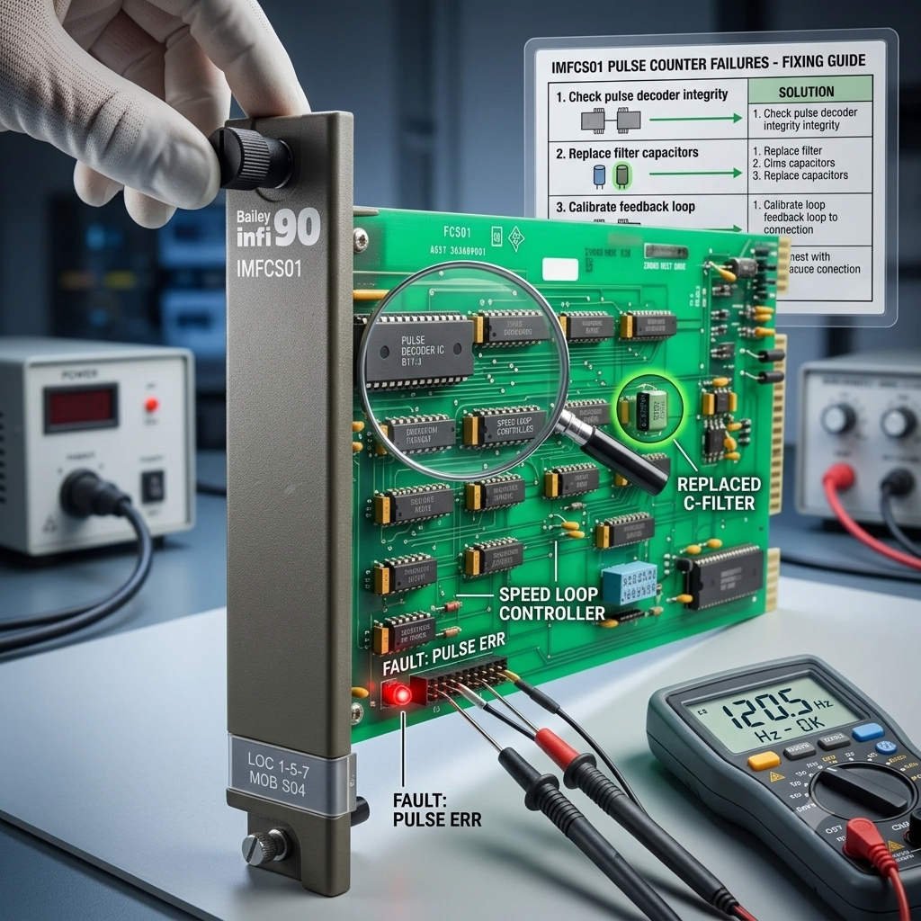
Fixing IMFCS01 Pulse Counter Failures in Turbine Speed Loops

Resolving IMFCS01 Pulse Counting Failures in Steam Turbine Speed Control Systems

Reliable speed measurement remains a critical pillar of turbomachinery protection and load control within industrial automation. In distributed control systems (DCS), the ABB Bailey INFI 90 / Symphony series IMFCS01 Frequency Counter Module plays a vital role. This module frequently conditions and counts pulse signals generated by proximity probes and preamplifiers (Proximitors). However, engineers often encounter a frustrating scenario during commissioning or post-overhaul restarts. The Proximitor functions correctly, and signal cables show excellent continuity, yet the IMFCS01 module registers a wheel speed of zero RPM. This comprehensive guide diagnoses this common field issue and offers actionable technical solutions.

Understanding Why the IMFCS01 Fails to Capture Turbine Pulse Signals

A typical steam turbine speed measurement loop routes a proximity probe through a Proximitor to output pulses directly into the IMFCS01 module. Many control room technicians overlook the fundamental operation of the hardware. The IMFCS01 does not directly read raw frequency. Instead, internal comparator circuits must detect a pulse crossing a predefined voltage threshold before registering a count. If field personnel misconfigure this threshold higher than the actual peak voltage of the incoming wave, the card remains blind to the pulse edges. Industrial facilities frequently experience this issue after turbine overhauls, sensor replacements, or when splitting speed loops to feed third-party vibration monitoring systems like Bently Nevada 3500 racks.

Consider the following signal interaction matrix based on real-world field data:

Preamplifier Output (Vpp)IMFCS01 Threshold SettingCounting StatusOperational Outcome
2.5V Pulse5V (Mid Threshold)No CountingZero RPM Reading / False Trip Hazard
8.0V Pulse5V (Mid Threshold)Normal CountingStable Speed Control
12.0V Pulse10V (High Threshold)Normal CountingStable Speed Control
3.0V Pulse10V (High Threshold)No CountingDCS Speed Signal Loss Fault

The Critical Role of Threshold Configuration in Rotating Machinery Protection

The primary value of the IMFCS01 lies in providing high-integrity speed processing for safety-critical control systems. In petrochemical plants, power generation facilities, and gas pipelines, sudden speed signal loss triggers devastating consequences. For example, according to API 670 standards for machinery protection, a loss of speed feedback can cause emergency overspeed trip valves to close unexpectedly. Consequently, these nuisance trips result in massive financial losses due to unplanned production downtime. Properly managing input sensitivity via physical hardware jumpers significantly improves signal-to-noise ratios, especially when processing attenuated signals across long field cable runs.

Step-by-Step Procedure to Adjust the IMFCS01 Threshold Jumper

While minor board variations exist across different manufacturing generations of the Bailey INFI 90 hardware, most modules utilize a standardized jumper layout. Technicians should execute the following steps to ensure precise calibration:

Step 1: Measure the Actual Pulse Amplitude
Connect an isolated, calibrated digital oscilloscope directly to the terminal block of the speed input channel. Do not rely solely on a digital multimeter, as multimeters average out the voltage. Record the peak-to-peak voltage (Vpp), the low state voltage, and the wave shape. For example, if a probe yields a 0V low state and a 4.2V high state at 3,000 Hz, the effective pulse peak is 4.2V.

Step 2: Inspect the Hardware Jumper Configuration
Isolate the loop power and safely extract the IMFCS01 card from its module mounting slot. Locate the hardware jumpers on the printed circuit board (PCB), typically labeled as JP1, JP2, JP3, or designated under a “Threshold Select” silk screen. Review the standard voltage matrix:

  • LOW Position: Activates a 1V to 2V threshold for low-voltage pulses.
  • MID Position: Establishes a nominal 5V threshold for standard industrial logic.
  • HIGH Position: Sets a 10V threshold designed for high-amplitude signals.

Step 3: Apply the 40% to 60% Field Engineering Rule
As a rule of thumb gained from decades of plant maintenance, always configure the threshold to sit between 40% and 60% of the true pulse peak voltage. If the measured pulse peak is 4.2V, the 10V high setting will fail entirely. Therefore, move the jumper to the LOW threshold position (1-2V) to guarantee robust triggering across all turbine operational speeds.

Step 4: Re-energize and Verify Control Loops
Reinsert the module, power up the rack, and monitor the DCS graphics. Verify the RPM display, check the Sequence of Events (SOE) logs for chatter, and trend the speed variable. If the speed curve remains flat and free of noise spikes, the threshold is correct.

Technical Specifications and Environmental Challenges

Managing turbine speed inputs requires balancing three key engineering parameters:

  • Input Edge Detection: Setting the threshold too high causes dropped counts, while setting it too low invites high-frequency noise interference. Engineers must adapt these settings when field cables exceed 100 meters, as cable capacitance degrades signal amplitude by up to 30%.
  • Maximum Frequency Limits: Consider a 60-tooth speed wheel spinning at 10,000 RPM. The input frequency reaches exactly 10,000 Hz ($10,000 \times 60 \div 60 = 10,000\text{ Hz}$). If this approach nears the upper processing limits of your I/O card, it introduces processing lag and timing errors into overspeed protection logic.
  • Galvanic Isolation: Turbine decks contain severe electromagnetic interference (EMI) from high-voltage generators, exciters, and variable frequency drives (VFDs). The integrated opto-isolation on the IMFCS01 protects internal logic from common-mode voltage spikes and reduces false overspeed trips.

Best Practices for Field Installation and Maintenance

🔧 Quick Field Checklist for Speed Loops:
1. Always routing speed signal cables through dedicated, grounded galvanized conduits.
2. Maintain a minimum 30cm separation between pulse signal lines and high-voltage AC cables.
3. Ensure the overall cable shield is grounded at a single point, preferably at the DCS cabinet ground bus.

Furthermore, plants located in areas prone to lightning must install dedicated signal surge protective devices (SPDs) on the DIN rail before the signal enters the IMFCS01 card. This prevents induced high-voltage transients from burning out the delicate comparator circuits inside the module.

An Expert Commentary from Powergear X Automation

From our perspective at Powergear X Automation, many control system issues blamed on “dead I/O cards” actually stem from simple configuration oversights. As legacy control systems interface with modern instrumentation, voltage mismatches occur more frequently. When upgrading or maintaining critical infrastructure, ensuring proper impedance and threshold matching saves hundreds of hours of troubleshooting. If you require verified, high-reliability replacement parts or upgraded modules for your legacy control systems, explore the fully tested inventory available at Powergear X Automation to secure your plant’s operational uptime.

Real-World Application Scenario

During a recent turnkey upgrade at a combined-cycle power plant, the plant replaced an old mechanical overspeed governor with a triple-modular redundant electronic system. Technicians routed the secondary speed pulses into an existing Bailey INFI 90 DCS running an IMFCS01 card. Upon startup, the DCS showed zero RPM, instantly triggering a start-failure lock. While the team initially suspected a faulty module, an oscilloscope check revealed that the new sensor only outputted a 3.8V peak signal because of an added safety barrier line resistance. The IMFCS01 jumper was set to the default MID (5V) position. Moving the jumper to the LOW position resolved the issue instantly, allowing the plant to synchronize to the grid on schedule.

Frequently Asked Questions (FAQs)

Q1: Does a flat-line zero RPM reading on the IMFCS01 mean the module must be replaced?
No, a zero reading rarely indicates immediate hardware failure if the card status LEDs are normal. Most incidents stem from incorrect threshold jumper settings, oxidized terminal connections, or signal attenuation caused by long field wiring. Always check the pulse waveform with an oscilloscope before purchasing replacements.

Q2: Can the IMFCS01 handle direct TTL signals from modern digital encoders?
Yes, provided the TTL signal voltage levels cross the configured threshold. Since standard TTL high states sit around 5V, the MID or LOW threshold jumper settings must be verified on the card to ensure the module registers the rising and falling edges accurately.

Q3: How does cable length affect the threshold settings on frequency counter modules?
Longer cables increase total loop resistance and capacitance, which rounds off the sharp edges of square waves and reduces the peak voltage. A pulse that leaves a Proximitor at 5V might arrive at the control cabinet at 3.2V. In these cases, technicians must lower the threshold jumper to compensate for this signal degradation.

Back to Top
Product has been added to your cart