Prevent Inverter Shoot-Through on GE IS210BPPCH1AD Modules
Preventing Inverter Bridge Shoot-Through: Dead Time Rules for GE IS210BPPCH1AD
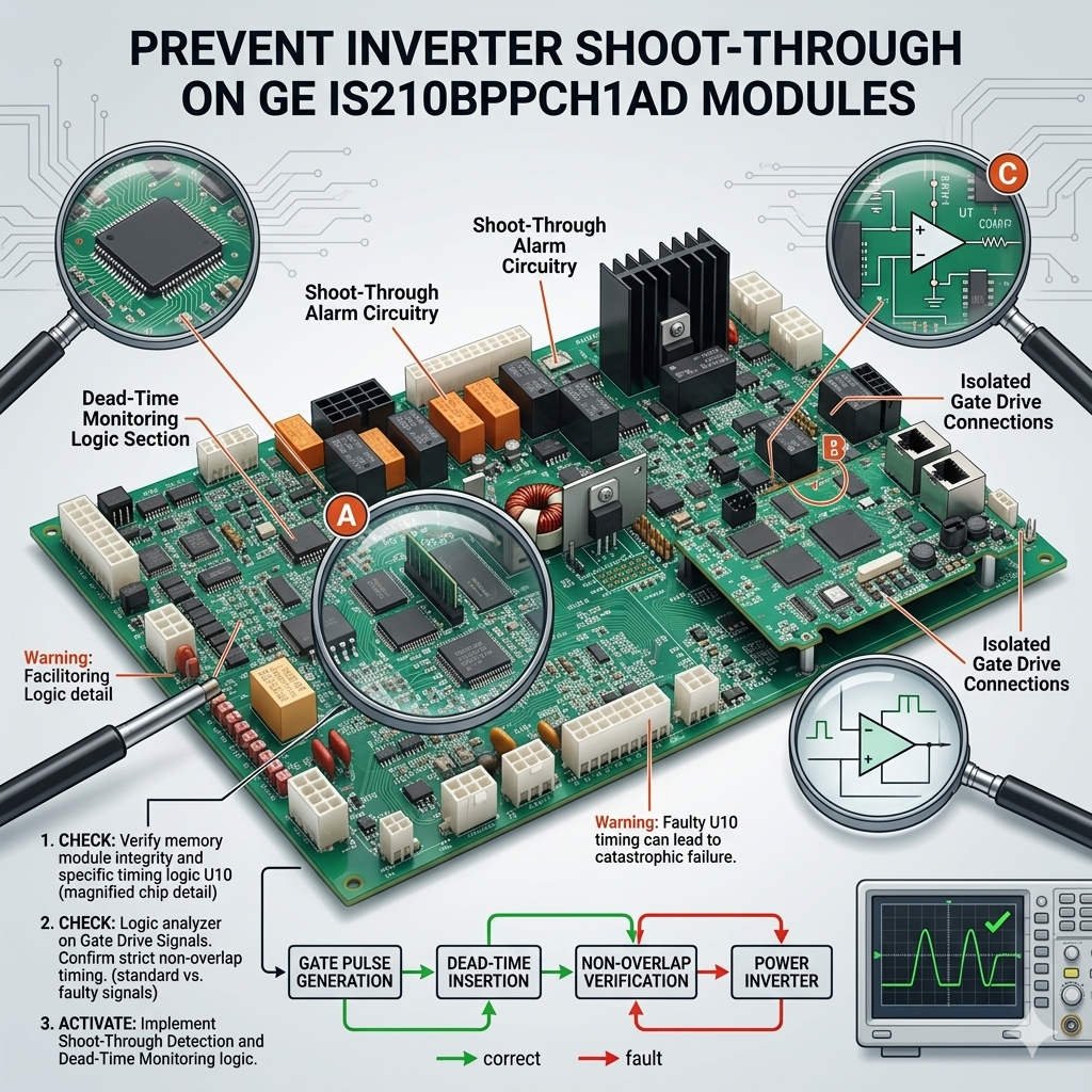
In high-power industrial automation systems, precise timing dictates equipment survival. The GE IS210BPPCH1AD and its predecessor, the IS210BPPCH1AC, handle critical PWM control logic. These processor boards coordinate gate pulses inside excitation and turbine control systems. However, incorrect dynamic dead time configurations can trigger catastrophic inverter bridge shoot-through failures. This technical breakdown explores how these modules manage semiconductor switching and prevent expensive hardware destruction.

The Operational Principle of Dynamic Dead Time Control
The primary function of the BPPCH series involves inserting a non-overlap interval during PWM transitions. This safety buffer, known as dead time, prevents the upper and lower bridge arms from conducting simultaneously. If both IGBTs turn on together, a massive short-circuit current collapses the DC bus. The IS210BPPCH1AD calculates this timing dynamically to accommodate turn-off delays and fiber-optic latency. Therefore, precise microsecond-level coordination isolates the high-voltage DC link from destructive cross-conduction events.
Thermal Drift Risks in Heavy Duty Drive Systems
Commissioning engineers often test control boards under moderate laboratory conditions. However, full-load operation in steel mills or petrochemical plants increases internal cabinet temperatures significantly. As power semiconductors heat up, their native turn-off characteristics slow down considerably. Driver propagation delays shift concurrently, which silently erodes the configured dead time safety margin. Consequently, a setting that appears stable during startup may fail after hours of continuous reactive power strain.
Industrial failure reports indicate that nearly 25% of power module blowouts stem from uncompensated thermal drift. The BPPCH control board must account for this switching dispersion across all active bridge channels. Moreover, electromagnetic noise from massive variable frequency drives can corrupt the pulse synchronization clock. When clock jitter decreases the effective dead time window, the system experiences localized thermal asymmetry before ultimate failure.
Selecting Between IS210BPPCH1AD and IS210BPPCH1AC
Choosing the correct board generation requires careful evaluation of your existing GE EX2100 or Mark VIe architecture. The newer IS210BPPCH1AD features optimized component layouts for better noise rejection. Furthermore, its updated EEPROM configuration path handles modern high-speed IGBT characteristics more effectively than the older “1AC” variant. However, these generations are not automatically plug-and-play interchangeable across every legacy system version.
Before executing a hardware swap, engineers must verify the active firmware checksum inside ToolboxST. Mixing older backplane interfaces with newer BPPCH boards can introduce subtle PWM timing deviations. Therefore, procurement teams should consult compatibility matrices to ensure exact I/O mapping consistency. For assistance with legacy system migration and genuine GE parts, professionals rely on trusted providers like Powergear X Automation Limited.
Field Deployment Rules for Power Conversion Cabinets
- ✅ Oscilloscope Verification: Measure actual gate waveforms with differential probes under loaded operational conditions.
- ⚙️ Component Revalidation: Recalculate dead time safety margins whenever replacing old IGBTs with newer generations.
- 🔧 Signal Protection: Isolate control grounding from power tracks and minimize fiber-optic cable bending radii.
Strategic Perspectives from Powergear X Automation Limited
At Powergear X Automation Limited, we advise against narrowing dead time margins to achieve minor harmonic improvements. In heavy factory automation applications, protection reliability must always supersede aggressive waveform optimization. We have seen numerous bridge rebuilds that could have been avoided by maintaining documented baseline records. If your facility requires robust spare parts planning, browse our specialized inventory at https://www.powergearx.com/ for verified industrial electronics.
Industrial Application Scenarios
In thermal power stations, the EX2100 excitation system regulates the main generator field current. Utilizing the IS210BPPCH1AD ensures steady voltage regulation during rapid load rejections. Similarly, large offshore gas compressor skids utilize these rugged control processors to withstand severe grid voltage fluctuations. These high-availability setups confirm that conservative timing values protect multimillion-dollar assets from catastrophic electrical failure.
Frequently Asked Questions (FAQ)
1. What immediate symptoms precede a shoot-through failure caused by control board timing?
Operators usually observe sudden, random inverter overcurrent trips and severe DC link ripple voltage increases. Audible noise changes within the cabinet and distinct temperature imbalances between matching bridge arms also indicate immediate danger.
2. Can I transfer the EEPROM data directly from an old 1AC module to a new 1AD board?
Direct transfer without validation is dangerous. While the core parameter structure matches, minor structural revisions inside the firmware compilation require verification through the ToolboxST system tool to ensure timing accuracy.
3. How does poor fiber-optic signal quality mimic a dead time configuration error?
Contaminated fiber-optic connectors cause transmission delays and increase pulse transition jitter. This jitter randomly shortens the physical dead time interval at the gate driver terminal, even if the software parameters are perfectly accurate.