Over 50,000 hot-selling automation module components.
Step-by-Step Setup Guide for GE PACSystems RX3i PLC: Mastering Industrial Automation

Step-by-Step Setup Guide for GE PACSystems RX3i PLC: Mastering Industrial Automation

Why the PACSystems RX3i is Crucial for Modern Control Systems

The GE PACSystems RX3i is a powerful PLC (Programmable Logic Controller). It is a key component in modern industrial automation. This controller offers high-speed processing and robust features. Its advanced capabilities support complex control tasks. Many engineers rely on the RX3i platform. Its versatility makes it suitable for various factory automation needs. We will explore the necessary setup steps below. This guide ensures a smooth and efficient deployment process. Understanding this platform provides a significant industry advantage.

Step-by-Step Setup Guide for GE PACSystems RX3i PLC: Mastering Industrial Automation

Initial Hardware Configuration and Module Installation

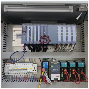
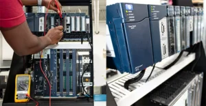
Begin the setup by mounting the main rack or backplane. Secure it firmly in the electrical panel. Next, install the main CPU module. This module is the brain of the control systems. Ensure all expansion modules are correctly seated. These modules may include I/O, communication, or specialized cards. Always check the physical connections carefully. A loose connection can cause system instability. Therefore, meticulous hardware setup is extremely important. This foundational step dictates the reliability of your system.

Connecting Power and Grounding: Ensuring System Integrity

Proper power and grounding are non-negotiable for any PLC. Connect the primary power source to the CPU and the power supply module. Refer to the GE product manual for exact voltage specifications. Incorrect voltage can damage sensitive electronics. Moreover, robust grounding minimizes electrical noise and interference. Use dedicated grounding points on the backplane. Good grounding protects your system from surges. This attention to detail upholds the principle of trustworthiness (E-E-A-T).

Software Installation and Project Creation

The PACSystems RX3i utilizes the Machine Edition (ME) software. Install this programming environment onto your engineering workstation. After installation, launch the ME application. Create a new project specific to your application. Select the correct RX3i CPU type from the hardware catalog. In addition, configure the rack and add all installed modules virtually. This digital representation must match your physical setup perfectly. This step establishes the basis for all control logic.
Step-by-Step Setup Guide for GE PACSystems RX3i PLC: Mastering Industrial Automation

Establishing Communication and Downloading the Initial Program

Configure the communication driver settings in the ME software. Typically, this uses an Ethernet connection. Assign a unique IP address to the RX3i CPU. The IP address must fit your plant network scheme. Once communication is verified, a successful connection icon will appear. Write a simple test program, perhaps a basic I/O check. As a result, you can download this initial program to the PLC. Switching the PLC to ‘Run’ mode verifies basic operational success. My own experience shows this simple test prevents later frustration.

Configuration of I/O Modules and Tag Database

The correct configuration of I/O is vital for DCS integration and control. Double-click each module in the ME software to set parameters. These include addressing, input filtering, or output type (e.g., analog, discrete). Define meaningful names for all I/O points in the tag database. Descriptive tags improve program readability and troubleshooting. However, avoid overly complex tag names that might confuse others. Clear documentation enhances the overall authority of your system design.

Author’s Insight: The Trend Toward Cybersecurity

The integration of industrial automation systems now demands strong cybersecurity. The RX3i offers features like secure boot and enhanced authentication. Engineers should prioritize network segmentation for PLCs. Never connect a control network directly to the public internet. This proactive approach protects critical infrastructure. Therefore, modern setup guides must include security considerations. This is my professional view on the evolving control landscape.

Step-by-Step Setup Guide for GE PACSystems RX3i PLC: Mastering Industrial Automation

Post-Setup Validation and System Documentation

Thoroughly test all hardware and software functionalities. Validate every input and output point. Check the system’s response to various operational scenarios. Document all IP addresses, tag definitions, and configuration settings. Comprehensive documentation is crucial for future maintenance. A well-documented system reflects high expertise and trustworthiness.

Application Scenario: High-Speed Packaging Line

The RX3i excels in high-speed, demanding applications. Consider a scenario in a packaging facility. The fast processing speed of the RX3i accurately coordinates multiple servo motors. It manages vision systems for quality checks and integrates safety functions. This application highlights the PLC’s power in complex motion control and data handling, a staple of advanced factory automation.

Discover Advanced Industrial Solutions

Are you looking to optimize your industrial automation projects with the power of GE PACSystems RX3i or other robust control systems? Learn how a leading solutions provider can elevate your facility’s performance.

3300 XL 8 mm Probe System Wiring Guide for Industrial Automation

3300 XL 8 mm Probe System Wiring Guide for Industrial Automation

Mastering Your 3300 XL 8 mm Probe System: A Complete Wiring Diagram Guide

The Bently Nevada 3300 XL 8 mm probe system is a critical component in industrial automation. It provides precise, non-contact measurements for machinery protection. A correct wiring setup is paramount. This guide provides a complete wiring diagram overview. It also offers essential insights for seamless integration into your control systems.

Understanding the 3300 XL Probe System Components

The 3300 XL system consists of three main parts. First, the probe measures displacement or vibration. Next, the extension cable connects the probe to the proximity sensor. Finally, the proximity sensor (or transducer) converts the measurement into a voltage signal. Proper wiring must connect these three components. It then sends the signal to your main factory automation system. Each component plays a vital role in accurate data collection.

3300 XL 8 mm Probe System Wiring Guide for Industrial Automation

The Core Wiring Diagram: From Probe to Terminal Block

Wiring the 3300 XL system follows a simple three-wire setup. This configuration includes Power, Common, and Signal. The proximity sensor has three terminals. One terminal connects to the DC power supply. Another connects to the common or ground. The third terminal carries the output signal. This signal is a DC voltage proportional to the probe’s gap. Therefore, a secure connection to all three terminals is essential. Loose connections can introduce noise or cause signal loss.

Connecting to Control Systems: PLC and DCS Integration

The 3300 XL system’s signal output must connect to a PLC (Programmable Logic Controller) or DCS (Distributed Control System). The output signal can be fed directly into an analog input card. You should ensure the PLC or DCS input module is configured for the correct voltage range. This ensures accurate signal interpretation. Moreover, a dedicated analog input card is highly recommended. Using a dedicated card minimizes electrical noise and cross-talk. This is crucial for precise machine health monitoring.

3300 XL 8 mm Probe System Wiring Guide for Industrial Automation

Ensuring Power and Grounding Integrity

A stable power supply is non-negotiable for reliable operation. The 3300 XL requires a clean, regulated DC power source. Proper grounding is equally important. The system’s common terminal must be tied to the chassis ground. This creates a clear path for electrical currents. As a result, it prevents ground loops and signal interference. Proper grounding also protects against electrical surges. It is a fundamental practice for all robust industrial automation setups.

Troubleshooting Common Wiring Issues

Experience shows that wiring issues often arise. The most common problem is signal drift or no output. Always check power supply voltage first. Next, inspect all connections for looseness or corrosion. A simple continuity test can verify cable integrity. Additionally, always use shielded cables. The shielding should be grounded at one end only. This prevents noise pickup from surrounding equipment. A well-executed wiring plan proactively prevents these common issues.

Author’s Insight: Investing in Reliability

A thorough and meticulous wiring job is not just a technical step. It is a critical investment in data integrity and system reliability. In my view, overlooking the fundamentals of wiring is a significant risk. Accurate data from your 3300 XL system directly impacts predictive maintenance decisions. Therefore, a small investment of time in correct wiring pays huge dividends. It ensures your machinery remains safe and operational.

3300 XL 8 mm Probe System Wiring Guide for Industrial Automation

Real-World Application: Turbine Monitoring Solutions

The 3300 XL probe system is ideal for monitoring axial thrust on steam turbines. Its wiring diagram connects the probe to a PLC. The PLC then processes the data. This data is displayed on an HMI. If the thrust exceeds a predefined limit, the PLC triggers an alarm. This proactive solution prevents catastrophic failure. A reliable wiring setup is the foundation of this entire system. It ensures the data fed into the PLC is always correct.

To discover more about our advanced solutions and high-quality industrial products that integrate with systems like the 3300 XL, visit our website. Our portfolio covers a wide range of needs for industrial automation and asset management.

Discover how Powergear X Automation Limited can support your projects.

Exploring the Compatibility of GE Fanuc PACSystems RX3i with Legacy Systems

Integrating Bently Nevada 9200 Velocity Data into Your Existing PLC/DCS Alarm Strategy

Introduction

As an operations manager and engineer with years of experience in industrial automation, I’ve seen firsthand the challenges of managing disparate systems for predictive maintenance. You’ve invested in vibration monitoring with Bently Nevada 9200 velocity sensors, and your plant runs on a robust PLC/DCS. The next logical step is to bridge the gap between them, creating a unified alarm strategy that simplifies operations and boosts efficiency.

Integrating 9200 Velocity Data into PLC/DCS Alarm Strategy

Integrating 9200 Velocity Data into PLC/DCS Alarm Strategy

Why Integrate? The Power of a Unified View

Integrating your Bently Nevada 9200 velocity data directly into your PLC/DCS offers significant advantages. Currently, you might be relying on separate software or manual checks to interpret vibration data. This creates silos of information and can lead to delayed responses to critical equipment issues.

  • Centralized Alarm Management: All your alarms, from process deviations to vibration anomalies, appear in one place.
  • Improved Decision-Making: Operators gain immediate access to vital equipment health data.
  • Reduced Training Burden: Eliminates the need for teams to learn new software interfaces.
  • Enhanced Automation Opportunities: Develop sophisticated control strategies like soft shutdowns based on vibration levels.
  • Cost Savings: Prevent catastrophic failures through early detection.

Overcoming Integration Hurdles: A Practical Approach

Integrating specialized vibration monitoring systems with standard control systems can seem daunting. However, it’s often more straightforward than you think.

  • Identify Available Outputs: Confirm analog outputs from your Bently Nevada 9200 system.
  • Select PLC/DCS Analog Inputs: Dedicate appropriate analog input modules.
  • Scaling and Calibration: Scale incoming 4-20mA signals to represent actual vibration units.
  • Alarm Logic Configuration: Configure warning and critical alarms based on vibration limits.
  • Human-Machine Interface (HMI) Integration: Display vibration data prominently on HMI screens.

My Unique Take: Beyond Just Alarms

While integrating for alarm management is the primary goal, don’t stop there.

  • Trending and Historical Data: Utilize PLC/DCS data logging to track vibration trends.
  • Integration with EAM: Link PLC/DCS data with Enterprise Asset Management systems.
  • Condition-Based Control: Implement logic for automatic parameter adjustments.
  • Leverage Existing Expertise: Empower control system engineers with proper documentation.

Conclusion: A Smarter Path to Reliability

Integrating your Bently Nevada 9200 velocity data into your existing PLC/DCS alarm strategy is a powerful step towards a more efficient and reliable operation. It consolidates information, empowers your operators, and ultimately reduces unplanned downtime and maintenance costs.

Ready to simplify your predictive maintenance strategy? Powergear X Automation Limited offers the expertise and products you need for seamless integration. Click here to explore our solutions and take the next step toward enhanced plant reliability!

Coal Ash Processing in Thermal Power Plants

SCADA Solutions for Coal Ash Processing in Thermal Power Plants

📌 Project Overview

Datang Ningde Power Plant operates four coal-fired units (2×600MW + 2×660MW) with an annual fly coal ash processing capacity of 360,000 tons. The automation system ensures efficient solid waste utilization, producing Grade I/II fly ash. Key objectives include:

  • 📡 Real-time monitoring for process optimization
  • 🔒 Safety interlocks to prevent equipment failures
  • 📊 Historical data traceability for quality control

🏗 Control System Architecture

The system utilizes Siemens PLCs for local control and Advantech industrial PCs with InTouch SCADA for visualization.

  • 🌡 The system displays pressure and temperature parameters both locally and on DCS screens.
  • 🔄 Redundant communication interfaces ensure seamless integration with plant-wide networks.

🎯 Core Functional Requirements

  • 🖥 Local control panels provide pressure/temperature displays and allow operators to adjust setpoints.
  • 📈 Historical temperature data is stored for quality audits and compliance.
  • 🛢 Dual oil pumps in lubrication stations enable automatic fault switching, ensuring uninterrupted operation.
  • 🚨 Differential pressure switches trigger alarms and mill shutdowns during abnormal conditions.

🛡 Safety and Interlocking Logic

  • ⚠️ Oil pressure indicators & differential pressure alarms prevent equipment damage.
  • 🔌 The PLC implements interlock trip logic, automatically halting operations during critical faults.
  • 🌍 Remote communication interfaces support centralized monitoring via Modbus/TCP protocols.

🚀 Operational Advantages

  • Real-time DCS visualization reduces manual inspections.
  • Automated pump switching minimizes downtime and enhances reliability.
  • Historical trend analysis supports predictive maintenance strategies.
  • Standardized protocols simplify third-party system integration.

🔮 Future Scalability

📡 Modular design supports additional sensors or processing lines.
☁️ Cloud connectivity could enhance remote diagnostics and data analytics.
🤖 Machine learning algorithms may be implemented to optimize grinding efficiency in later phases.

If you are looking for DCS integration system, please feel free to Powergear X Automation Limited.

Back to Top
Product has been added to your cart