
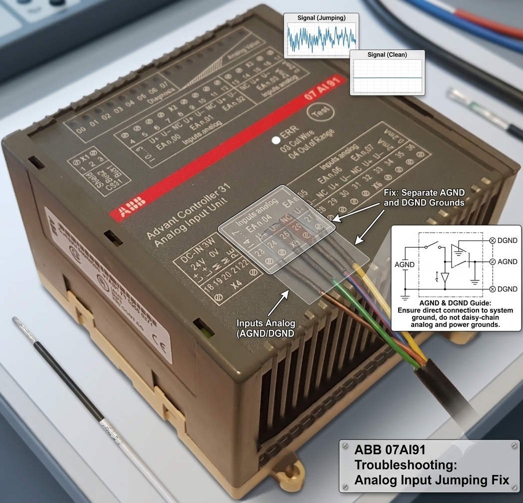
Correcting AGND and DGND Ground Loops on DCS Modules
Fixing ABB DCS 07AI91 Analog Input Fluctuations via AGND and DGND Isolation
In industrial automation, field engineers frequently encounter signal instability on analog input modules. Specifically, the ABB DCS 07AI91 analog input card often exhibits severe data fluctuations or random process variable (PV) jumps. While many technicians immediately suspect faulty transmitters or bad analog-to-digital (A/D) converters, the root cause usually lies elsewhere. Improper grounding of the Analog Ground (AGND) and Digital Ground (DGND) on external terminals creates devastating ground loops.
Managing high-precision analog inputs requires strict adherence to single-point grounding principles. If you mismanage these reference points, electrical noise will easily corrupt your low-level loops. Consequently, control room operators will notice erratic spikes on their trend screens. This technical guide delivers practical solutions to eliminate ground-loop interference and restore rock-solid signal stability to your control systems.
The Operational Cost of Signal Noise in Process Automation
The 07AI91 analog input module serves as a critical data gateway by converting 4-20mA and 0-10V field signals into digital values. In continuous processing industries like oil and gas, chemical manufacturing, and power generation, accurate analog measurements directly determine PID loop performance. Therefore, minor signal fluctuations can destabilize an entire production line.
At Powergear X Automation, we observe that incorrect AGND and DGND terminal wiring damages control quality even when field instruments operate perfectly. Experienced engineers know that optimizing the external grounding architecture resolves signal jumping far more effectively than replacing expensive hardware. Protecting signal integrity ensures tighter process control, lowers equipment stress, and reduces unplanned downtime.
Deconstructing 07AI91 Technical Specifications and Noise Vulnerability
High-resolution A/D converters make the 07AI91 module highly sensitive to subtle process changes. However, this extreme precision also renders the card vulnerable to common-mode voltage noise. When the grounding system is poorly designed, the high-resolution architecture inadvertently amplifies electrical interference instead of filtering it out.
Field data indicates that if a process variable jumps by 1% to 3% while the actual physical process remains steady, grounding layout errors are usually the culprit. Although the 07AI91 features internal galvanic isolation, this feature cannot compensate for external wiring blunders. Industrial isolation shields the internal system bus from field faults; it does not grant permission to create arbitrary external ground paths.
Step-by-Step Field Guide to AGND and DGND Terminal Wiring
To eliminate data jumping on the 07AI91 module, you must strictly isolate AGND and DGND on your external marshalling terminals. Please follow these verified deployment steps to ensure clean signal acquisition:
- Enforce Single-Point Grounding: Never bridge the AGND and DGND terminals together at the field terminal block. ABB engineers design these systems to connect at a single, controlled reference point inside the cabinet chassis.
- Isolate Terminal Connections: Route the AGND wire exclusively to the analog signal reference plane and keep the DGND dedicated to digital logic returns.
- Prevent Ground Loops: Double-bonding these grounds creates a closed loop that invites stray electromagnetic currents to circulate through your analog loops.
Optimizing Shield Grounding and 24VDC Power Quality
Proper cable shield management provides the next line of defense against factory automation noise. Technicians must terminate instrument cable shields solely at the control cabinet side using a dedicated copper ground bar. Leaving the field instrument side ungrounded prevents earth potential differences from driving current through the shield.
In addition, you must verify the quality of your 24VDC power distribution system. Use an oscilloscope to measure DC power ripple, ensuring it stays well below 100mV peak-to-peak. Furthermore, check the AC voltage between AGND and the Protective Earth (PE) bus. If this potential difference exceeds 1VAC, you must systematically audit your plant-wide grounding grid to locate the leakage source.
Strategic Cable Routing in High-Interference Environments
Heavy electrical machinery like variable frequency drives (VFDs), large motors, and soft starters generate massive electromagnetic fields. To safeguard your low-voltage analog loops, you must maintain rigid physical separation during cable installation. Run your analog signaling lines in separate, grounded steel conduits or distinct cable tray tiers.
Always maintain a minimum clearance of 300mm between parallel analog lines and high-voltage power cables. When signal and power runs must intersect, cross them strictly at a 90-degree right angle to minimize inductive coupling. These clean installation habits eliminate the vast majority of ghost faults that engineers mistake for hardware failures.
Industrial Case Study: Resolving Flow Meter Fluctuations
During a recent DCS upgrade at a major chemical plant, an engineer reported that a critical electromagnetic flow meter exhibited severe PV jumping after commissioning. The trend line showed random 2.5% spikes every few minutes, causing the downstream pneumatic control valve to stroke erratically. The site team initially suspected a defective 07AI91 card and replaced it twice, yet the problem persisted.
A deep audit by our team revealed that the installation contractor had jumpered AGND to DGND on the marshalling terminal strip to “simplify” wiring. This link allowed high-frequency noise from a nearby 110kW cooling pump VFD to feedback directly into the analog return path. By removing the external jumper and isolating the grounds according to standard factory automation specs, the flow meter signal stabilized instantly, proving the value of proper grounding rules.
Explore Premium Automation Hardware Solutions
Resolving complex signal anomalies requires both expert field practices and dependable control hardware. If you are looking to replace legacy components, expand your current DCS architecture, or source hard-to-find industrial control modules, we can assist you. Discover our comprehensive inventory of high-performance components and technical spares by visiting the Powergear X Automation platform today.
Frequently Asked Questions
Q1: Does a jumping PV value always indicate that the 07AI91 card is physically damaged?
No, physical hardware failure is actually rare. Field statistics show that roughly 50% of analog jump issues stem from grounding errors, 30% come from electromagnetic interference (EMI), and 15% relate to field transmitter faults. Less than 5% point to actual component degradation.
Q2: Can I ground both ends of an analog signal shield for extra protection?
Absolutely not. Grounding both ends of a shield creates a classic ground loop because different areas of a factory campus always have slightly different earth potentials. This voltage delta drives circulating currents through your shield, which induces heavy noise into your signal pairs via transformer action.
Q3: What are the main compatibility checks needed when replacing an older ABB analog card with a 07AI91?
You must verify the master controller firmware version, backplane bus compatibility, and your engineering software database configuration. Always check the manufacturer’s official compatibility matrix to ensure your channel assignments and signal range configurations map correctly without dropping data.