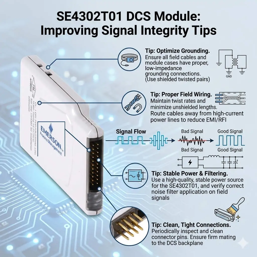
Over 50,000 hot-selling automation module components.
Yokogawa CP451-50: High-Performance DCS Processor Guide

Yokogawa CP451-50: High-Performance DCS Processor Guide

Understanding the Yokogawa CP451-50 High-Performance Processor for CENTUM VP

In the demanding world of industrial automation, the Yokogawa CP451-50 stands out as a critical component. This processor functions as the “brain” of the Distributed Control System (DCS). It manages complex logic and high-speed data processing. Many engineers view this module not just as hardware, but as a safeguard for plant stability. Therefore, understanding its technical advantages is essential for modern plant management.

Yokogawa CP451-50: High-Performance DCS Processor Guide

The Role of Deterministic Control in Large-Scale Plants

The CP451-50 earns its “high-performance” label by ensuring deterministic control. This means the controller executes tasks at precise intervals regardless of system load. In continuous process industries like oil and gas, timing is everything. If a PID loop lags during a pressure spike, the results can be catastrophic. Consequently, Yokogawa optimized this processor to handle massive I/O counts without compromising scan cycles.

Enhancing Communication Stability within Vnet/IP Networks

Modern factory automation relies heavily on seamless data exchange. The CP451-50 excels in managing Vnet/IP communications. It handles data traffic from Human Interface Stations (HIS) and safety systems simultaneously. Moreover, it maintains peak performance even during “alarm storms” or emergency shutdowns. This capability prevents the processor from becoming a bottleneck during critical operational transitions.

Built for Industrial Durability and Environmental Resilience

Reliability is a cornerstone of the E-E-A-T principle in control systems. The CP451-50 features a robust design that resists electromagnetic interference (EMC). While many commercial processors fail in high-temperature cabinets, this unit maintains thermal stability. My experience at Powergear X Automation shows that thermal management directly correlates with system lifespan. Using hardware with high design margins significantly reduces “grey zone” intermittent faults.

Best Practices for Power Quality and Hardware Installation

Superior hardware still requires a stable environment to function correctly. We often find that CPU instability stems from poor 24 VDC power quality rather than internal defects.

  • ✅ Verify DC power ripple levels during commissioning.
  • ✅ Use external surge suppressors in lightning-prone regions.
  • ✅ Ensure proper cabinet grounding to prevent signal noise.
  • ✅ Maintain clear airflow paths to prevent heat buildup.
  • ✅ Avoid mechanical stress on backplane connectors from heavy cables.

Strategies for Firmware Management and System Upgrades

Consistency in firmware is vital for long-term maintenance. Mixing different versions of CENTUM VP can lead to synchronization errors. Therefore, always consult the Yokogawa compatibility matrix before performing an online download. Our team suggests a “discipline-first” approach to software updates. This prevents subtle communication glitches during redundant controller switchovers.

Technical Summary Table

FeatureCP451-50 AdvantageImpact on Operations
ThroughputHigh-speed instruction executionTighter control over volatile processes
NetworkDual Vnet/IP supportReliable data flow during high traffic
DesignEnhanced thermal dissipationReduced risk of hardware failure
LongevityBackward compatible architectureLower Total Cost of Ownership (TCO)

Expert Commentary by Powergear X Automation

The shift toward “Smart Manufacturing” requires controllers that offer more than just basic logic. The CP451-50 represents a bridge between traditional DCS reliability and modern data demands. At Powergear X Automation, we believe that investing in high-headroom processors is a form of insurance. It allows for future expansions—like adding advanced process control (APC)—without replacing the entire infrastructure.

For genuine parts and expert technical support, we invite you to explore our solutions at Powergear X Automation. Our team helps you optimize your DCS for maximum uptime.

Real-World Application Scenarios

  • Petrochemical Refineries: Managing thousands of PID loops with sub-second response requirements.
  • LNG Terminals: Handling complex sequence tables for ship-to-shore loading operations.
  • Power Plants: Coordinating fast-acting control logic for turbine management and grid synchronization.

Frequently Asked Questions (FAQ)

1. How do I know if my current controller needs an upgrade?
Monitor your CPU load during peak production. If utilization consistently exceeds 60%, or if you experience “communication timeouts” during data-heavy operations, the CP451-50 is a necessary upgrade. High load leaves no room for emergency logic execution.

2. Can I replace an older CP451 model with the CP451-50 directly?
While physical mounting is often compatible, the software environment is the decider. You must verify that your current CENTUM VP revision supports the -50 variant. We recommend a full backup and a revision check to avoid “version mismatch” errors during the hot-swap process.

3. Does the CP451-50 improve plant safety metrics?
Indirectly, yes. By providing a stable, deterministic environment, it ensures that safety-related interlocks and alarms trigger without delay. A high-performance processor reduces the “jitter” in control responses, which is a key factor in maintaining safe operating envelopes.

Troubleshooting 140NOM25200C EMI Packet Loss

Troubleshooting 140NOM25200C EMI Packet Loss | Powergear X

Troubleshooting EMI-Induced Packet Loss in Schneider Modicon 140NOM25200C Modules

Defining the Role of Modicon Quantum in Mission-Critical Systems
The Schneider Electric Modicon Quantum 140NOM25200C serves as a cornerstone for Ethernet communication in demanding control systems. This module facilitates continuous data exchange between PLCs, HMIs, and SCADA platforms. In sectors like oil and gas or pharmaceuticals, its value depends on deterministic communication. However, external electromagnetic interference (EMI) often disrupts this stability. Understanding these disruptions helps engineers differentiate between true hardware failure and environmental noise.

Troubleshooting 140NOM25200C EMI Packet Loss

Identifying Intermittent Packet Loss Patterns Under EMI

EMI typically triggers burst-type packet loss rather than total communication blackouts. You may notice that TCP/IP sessions remain active while cyclic data updates experience significant lag. Consequently, SCADA systems might trigger sporadic timeout alarms that clear themselves within seconds. These “ghost faults” often baffle technicians because the hardware passes standard diagnostic tests. At Powergear X Automation, we frequently observe that these patterns point toward shielding issues rather than defective internal circuitry.

Evaluating Environmental Factors and Installation Risks

While the 140NOM25200C meets IEC 61131-2 standards, real-world cabinet conditions often exceed these test parameters. Packet loss frequently occurs when Ethernet cables run too close to high-current VFD motor leads. Furthermore, inconsistent grounding on painted backplates creates a high-impedance path for noise. When EMI penetrates the physical layer, it creates Cyclic Redundancy Check (CRC) errors. These errors force the module to drop frames, leading to the erratic performance seen in factory automation.

Analyzing Protocol Resilience and Latency Impacts

The 140NOM25200C utilizes standard TCP/IP, which offers some resilience through retransmission mechanisms. Nevertheless, excessive interference forces constant re-sending of data packets. As a result, network latency increases and PLC scan times may fluctuate. For high-speed interlocks and synchronized control systems, this jitter is unacceptable. Even if the PLC logic remains running, the delayed data can cause nuisance trips or reduced production efficiency in complex DCS environments.

Implementing Professional Shielding and Grounding Standards

Effective mitigation starts with physical separation and high-quality materials. Engineers should always utilize industrial-grade shielded Cat 5e cables for all Quantum installations.

  • Maintain at least 30 cm of clearance from high-voltage power lines.
  • Bond cable shields to a low-impedance earth ground at cabinet entry points.
  • Avoid floating shields to prevent the cable from acting as an antenna.
  • Install external Ethernet surge protectors for outdoor or refinery applications.
  • Verify that all terminations follow TIA/EIA-568-B industrial standards.

Strategic Insight by Powergear X Automation

In our experience, the 140NOM25200C is a robust piece of hardware, but it is often blamed for system-wide failures that are actually environmental. The industry is shifting toward more sensitive, high-speed data requirements. Therefore, the “it worked yesterday” mentality no longer applies to aging infrastructure. If you are experiencing intermittent “Link” LEDs or CRC errors, look at your grounding before ordering a replacement. Investing in proper EMC hygiene is always more cost-effective than repetitive hardware swaps.

Application Scenario: Chemical Processing Plant

A major chemical facility experienced random SCADA disconnects every time a large centrifuge ramped up. Although the 140NOM25200C was suspected of having a faulty port, a spectrum analysis revealed high-frequency noise leaking from a nearby VFD. By simply upgrading to double-shielded S/FTP cabling and improving the cabinet’s common ground bond, the “faulty” module returned to 100% uptime without replacement.

Frequently Asked Questions (FAQ)

Q: How can I verify if my communication lag is environmental or a module hardware defect?
Check the PLC diagnostic buffer for “Frame Errors” or “CRC Errors.” If these errors coincide with the startup of heavy machinery or VFDs, it is likely EMI. A failing module usually stays offline or fails to initialize regardless of external equipment activity.

Q: When purchasing a 140NOM25200C for an older system, what should I check first?
Check your existing cable type. Older systems often use unshielded twisted pair (UTP). Modern 140NOM25200C modules are more sensitive to noise than legacy serial counterparts, so upgrading to shielded cabling is a prerequisite for a successful retrofit.

Q: Is there a specific diagnostic tool for measuring this packet loss in real-time?
You can use managed switch port statistics or specialized industrial network Analyzers. Look for an increase in “Inbound Errors” on the specific port connected to the Modicon module. If the error count rises only during production hours, your issue is environmental interference.

For professional technical support and high-quality industrial components, visit the experts at Powergear X Automation to optimize your control system’s reliability.

Modicon 140CPU67160 Guide: High-Density PID Control Systems

Best Modicon Quantum CPU for PID: 140CPU67160 Performance

Overview

Finding the right controller for complex process logic can be a daunting task. At Powergear X Automation, we specialize in identifying high-performance hardware that stands up to real-world industrial demands. If you are looking to optimize your control architecture, explore our full range of solutions at Powergear X Automation.

Modicon 140CPU67160 Guide: High-Density PID Control Systems

What is the Best Modicon Quantum CPU for High-Density PID Control?

In the demanding world of industrial automation, precision is everything. While the Schneider Electric Modicon Quantum series offers various options, the 140CPU67160 stands out as the ultimate powerhouse for PID-intensive applications. This Unity-based processor redefined how engineers approach continuous process control. It successfully bridged the gap between traditional PLC logic and the complex regulatory requirements typically reserved for a DCS (Distributed Control System).

Unmatched Processing Power for Complex Loops

The 140CPU67160 offers superior clock speeds and optimized memory management compared to its predecessors. In my experience, this model handles hundreds of PID loops without compromising the overall scan time. Consequently, the controller maintains high update rates for critical variables like pressure and flow. This speed prevents the “lag” often seen in older factory automation setups, where heavy communication tasks might otherwise starve the control logic of resources.

The Advantage of Unity Pro and Control Expert

Transitioning from Concept-based software to Unity Pro (now EcoStruxure Control Expert) was a turning point for the Quantum line. This CPU utilizes advanced function block libraries that simplify complex tuning.

  • The CPU supports high-precision floating-point math for PID calculations.
  • Users gain access to integrated auto-tuning features.
  • Structured memory allows for better organization of large-scale control systems.
  • Diagnostic bits provide real-time feedback on loop health.

Reliable Performance Under Network Stress

Modern industrial automation environments are noisy with data from SCADA, historians, and remote I/O. Earlier CPUs, such as the 140CPU113, often struggled when Ethernet traffic spiked. However, the 140CPU67160 features a robust internal architecture that prioritizes control tasks. It effectively isolates the logic execution from network interrupts. This ensures that your PID outputs remain steady even when the plant network is under heavy load.

Field Strategies for Maximum Stability

Practical application requires more than just choosing the right part number. Based on field observations at Powergear X Automation, we recommend these technical best practices:

  • Install CPUs away from high-heat modules to prevent thermal throttling.
  • Match your firmware versions strictly to your software build.
  • Use dedicated power filtration to protect sensitive internal components.
  • Implement external surge protection for all long-distance Ethernet runs.
  • Segment your control network to reduce unnecessary broadcast traffic.

Application Case: Chemical Process Optimization

In a recent refinery project, a legacy system struggled with oscillations in temperature control. By upgrading to the 140CPU67160 and migrating to Unity-based PID blocks, the facility reduced setpoint deviation by 15%. The faster processing allowed for a tighter derivative gain, which neutralized sudden thermal disturbances. This shift not only improved product consistency but also significantly reduced energy consumption during the heating cycle.

Expert FAQ

Q: Can I keep my existing I/O when upgrading to the 140CPU67160?
Yes, you can retain your Quantum I/O modules and racks. However, you must convert the logic from Concept to Control Expert. This process requires careful validation of PID parameters.

Q: How does this CPU handle redundancy in PID-critical environments?
The 140CPU67160 supports Hot Standby configurations. This ensures that if the primary CPU fails, the secondary takes over without bumping the PID outputs. This bumpless transfer is vital for maintaining process safety.

Q: What is the primary sign that my current Quantum CPU is overloaded?
Monitor your “System Scan Time” in the diagnostic buffer. If the scan time fluctuates wildly when you open a SCADA screen, your CPU is likely struggling with communication overhead.

For more technical guides and high-quality automation hardware, visit Powergear X Automation today. Would you like me to compare this model’s PID capabilities with the newer M580 ePAC series?

Maximizing Precision with Quantum 140ATI03000C Analog Inputs

Maximizing Precision with Quantum 140ATI03000C Analog Inputs

Optimizing Signal Precision with the Modicon Quantum 140ATI03000C Analog Input Module

The Modicon Quantum 140ATI03000C serves as a cornerstone for stable signal acquisition in demanding industrial environments. In chemical plants and oil and gas facilities, precision is non-negotiable. This high-density analog input module converts critical low-level signals into actionable PLC data. However, achieving peak performance requires more than just installation. It demands a deep understanding of wiring integrity and grounding principles to prevent data corruption.

Maximizing Precision with Quantum 140ATI03000C Analog Inputs

Enhancing Control with High-Resolution Signal Conversion

The 140ATI03000C excels at high-resolution analog-to-digital conversion for 4–20 mA and ±10 V loops. This precision is vital for maintaining tight control over flow, pressure, and temperature variables. Nevertheless, higher sensitivity often makes the system more vulnerable to electromagnetic interference (EMI). At Powergear X Automation, we frequently observe “fluttering” values in the field. These fluctuations usually stem from unshielded cables placed too close to Variable Frequency Drives (VFDs).

The Critical Role of Channel Isolation and Grounding

Engineered to meet IEC 61131-2 standards, this module provides robust isolation across its input channels. Despite this design, performance depends heavily on localized grounding practices. If a potential difference exists between the field instrument and the PLC ground, common-mode noise emerges. This noise often manifests as random data spikes or persistent signal drift. Experienced technicians know that a missing single-point ground can easily mimic a hardware failure.

Maintaining Long-Term Reliability in Harsh Environments

The Quantum platform is renowned for its industrial-grade durability and EMC tolerance. Even so, environmental stressors like high humidity or aging terminal blocks can degrade performance. Intermittent channel errors often signal a gradual decline rather than a sudden catastrophic failure. Early detection of these anomalies prevents unplanned shutdowns. Furthermore, monitoring signal health ensures that safety interlocks do not trigger based on false or noisy data.

A Disciplined Maintenance and Diagnostic Strategy

When troubleshooting erratic readings, engineers must distinguish between external interference and internal hardware degradation. A systematic approach saves time and reduces unnecessary replacement costs. We recommend the following diagnostic and preventative steps:

  • Execute a Signal Swap Test: Move the suspect signal to a known-functional channel. Observe if the fluctuation follows the field wiring. Identify if the error remains on the original channel.
  • Implement Shielding Best Practices: Utilize twisted, shielded cables for all analog inputs. Ground the shield exclusively at the PLC side. Maintain a 200 mm gap from power cables.
  • Install External Surge Suppression: The 140ATI03000C lacks comprehensive built-in surge protection. Add external protectors for outdoor or high-induction areas. Prevent cumulative damage from frequent atmospheric surges.

Expert Insight from Powergear X Automation

In my professional view, the 140ATI03000C remains one of the most reliable modules in the industrial automation market. Most “failures” reported by users are actually environmental or installation-related issues. By focusing on EMI mitigation and proper cable routing, you can extend the lifecycle of your control systems significantly. Investing in high-quality shielding today prevents costly downtime tomorrow.

For more technical guides and premium Modicon components, visit Powergear X Automation.

Industrial Application Scenarios

  • Chemical Batch Processing: Monitoring exothermic reactions where even a 0.5% temperature deviation impacts product quality.
  • Oil & Gas Pipelines: Collecting long-distance pressure data where ground loops are common challenges.
  • Water Treatment Facilities: Integrating flow meters that are often exposed to external lightning risks.

Frequently Asked Questions

How can I tell if my module is failing or if it is just a noise issue?
If a single channel shows erratic behavior while others remain stable, perform a swap test. If the noise persists on the same channel regardless of the signal source, the internal circuitry is likely compromised.

What should I check when upgrading from older Quantum variants?
Always verify firmware compatibility within EcoStruxure Control Expert. Additionally, recalibrate your scaling parameters, as older modules may have different internal offsets that affect measurement accuracy.

Is it necessary to use a signal isolator with this module?
While the 140ATI03000C has internal isolation, adding external signal isolators is wise for high-risk loops. This provides an extra layer of protection for the module’s backplane against massive field surges.

Reliability Guide for Honeywell CC-TDOR01 Relay Output Modules

Reliability Guide for Honeywell CC-TDOR01 Relay Output Modules

How Honeywell CC-TDOR01 Modules Prevent Relay Contact Sticking

The Honeywell CC-TDOR01 Relay Output Module plays a vital role in modern control systems. In industries like oil and gas, a stuck relay can cause catastrophic failures. If a valve fails to close during an emergency, personnel safety is at risk. Therefore, Honeywell implements rigorous testing and diagnostic strategies to mitigate these risks.

Reliability Guide for Honeywell CC-TDOR01 Relay Output Modules

The Critical Impact of Contact Welding in Industrial Automation

Relay contact sticking, often called “welding,” occurs when contacts fuse together. This prevents the output from turning off, even when commanded. In factory automation, this leads to motors running unexpectedly or safety interlocks being bypassed. High-reliability sectors like chemical processing cannot afford these hidden failures. Consequently, Honeywell focuses on making these faults detectable through smart system architecture.

Verifying Output Integrity via Load Feedback Logic

The CC-TDOR01 does not include internal sensors to detect physical contact position. Instead, it relies on external feedback loops within the Experion PKS logic. Engineers typically pair the relay output with a digital input from the field device. If the controller sends an “OFF” command but the feedback remains “ON,” a discrepancy alarm triggers. This method ensures that stuck contacts do not remain hidden for long periods.

Manufacturing Stress Tests for Enhanced Reliability

Honeywell subjects every CC-TDOR01 module to intense stress testing during production. These tests include repeated on/off cycling under maximum rated loads. Technicians perform both hot and cold switching tests to simulate harsh plant environments. These procedures identify “micro-welding” issues before the hardware reaches the customer. As a result, the modules demonstrate high durability in continuous process applications.

Aligning Diagnostic Coverage with IEC 61508 Principles

While the CC-TDOR01 is not a standalone SIL-certified relay, its design supports safety standards. Honeywell encourages redundant feedback paths to increase diagnostic coverage. This approach aligns with IEC 61508 principles for safety-instrumented systems. By utilizing these system-level checks, operators can maintain a high level of process integrity. Furthermore, this architecture simplifies fault isolation during maintenance routines.

Expert Insights from Powergear X Automation

At Powergear X Automation, we observe that most relay failures stem from improper installation. Many technicians overlook the impact of high inrush currents from large solenoids. These surges cause rapid arcing, which is the primary cause of contact welding. We recommend always using interposing relays for heavy inductive loads. This practice protects your CC-TDOR01 and extends the lifespan of your DCS hardware.

Proven Field Practices for Long-Term Reliability

To maximize the life of your Honeywell modules, follow these technical guidelines:

  • Install External Surge Suppression: Use RC snubbers for AC loads and flyback diodes for DC loads.
  • Implement Periodic Proof Testing: Manually cycle critical outputs during scheduled shutdowns to verify operation.
  • Monitor Load Current: Ensure steady-state and inrush currents remain within the module’s specified limits.
  • Verify Terminal Assignments: Double-check wiring during upgrades to avoid accidental short circuits.

Application Scenario: Emergency Shutdown (ESD) Support

In an ESD scenario, a CC-TDOR01 might control a fuel shut-off valve. By integrating a limit switch feedback into the DCS, the system confirms the valve actually closed. If the relay sticks, the system immediately alerts the operator. This setup transforms a standard relay into a robust safety component through intelligent design.

For high-quality components and expert technical support, visit Powergear X Automation to explore our full range of Honeywell solutions.

FAQ: Understanding CC-TDOR01 Performance

Q1: Does the CC-TDOR01 have built-in surge protection?
No, it does not include internal suppression. You must install external diodes or snubbers to prevent arcing and contact welding.

Q2: Can I use this module for SIL-rated safety loops?
The module itself is not SIL-certified. However, it can be used in safety-related applications if you implement redundant feedback and logic-level diagnostics.

Q3: What is the most common cause of contact sticking in these modules?
Excessive inrush current from inductive loads like motor starters is the leading cause. Using an interposing relay is the best way to prevent this.

Honeywell CC-PAIH01 vs CC-PAIH51: Technical Comparison

Honeywell CC-PAIH01 vs CC-PAIH51: Technical Comparison

Honeywell CC-PAIH01 vs. CC-PAIH51: Maximizing C300 System Reliability

In the world of industrial automation, hardware choices determine long-term plant stability. Field engineers often view the CC-PAIH01 and CC-PAIH51 as interchangeable High-Level Analog Input (HLAI) modules. These components share the same physical form factor for the Honeywell C300 controller. However, the CC-PAIH51 represents a significant leap in hardware diagnostics and thermal efficiency. Our team at Powergear X Automation has analyzed these differences to help you prevent unscheduled downtime.

Honeywell CC-PAIH01 vs CC-PAIH51: Technical Comparison

The Role of HLAI Modules in Process Control

The CC-PAIH01 and CC-PAIH51 modules serve as the primary interface for field transmitters. They convert 4-20mA signals into digital data for the C300 controller. These modules must maintain millisecond-level accuracy in harsh refinery or chemical plant environments. While both units perform basic signal conversion, the CC-PAIH51 addresses critical “blind spots” found in older hardware. Consequently, this newer version provides better protection against loop shutdowns.

Advanced Internal Diagnostics for Predictive Maintenance

The “51” series offers superior self-testing capabilities compared to the legacy “01” model. In a standard DCS environment, a CC-PAIH01 failure often results in an immediate “Bad PV” (Process Variable) alarm. This sudden failure can trigger an emergency trip. Conversely, the CC-PAIH51 detects internal component degradation before a total failure occurs. This early warning allows technicians to perform a planned hot-swap. As a result, plants maintain higher availability and safety standards.

Enhanced HART Communication and Signal Stability

Both modules support HART (Highway Addressable Remote Transducer) digital communication. However, the CC-PAIH51 features improved impedance matching for modern field devices. This technical refinement is vital for cable runs exceeding 300 meters. Poor impedance matching often causes “ghost” device alerts in the Field Device Manager (FDM). Moreover, the CC-PAIH51 ensures a cleaner data path for complex multi-variable transmitters, such as Coriolis meters.

Thermal Management and Component Longevity

Heat is the primary enemy of electronics in crowded control cabinets. Industry data suggests that a 10°C rise in temperature can halve the lifespan of electrolytic capacitors. The CC-PAIH51 utilizes updated power management components that reduce heat output. These modules typically run 2°C to 3°C cooler than the CC-PAIH01. Therefore, upgrading to the “51” series significantly extends the Mean Time Between Failures (MTBF) for your control system.

Critical Field Rules for IOTA Compatibility

Engineers must exercise caution when managing I/O Termination Assemblies (IOTA). Both modules utilize the CC-TAIH01 or CC-TAIH11 IOTAs. However, you should never mix an ’01’ and a ’51’ on the same redundant pair. Internal timing differences can cause synchronization errors during a controller switchover. Additionally, always verify shield grounding at the marshalling panel. Proper grounding prevents ground loops from damaging sensitive A/D converters in these modules.

Strategic Guide for Hardware Upgrades

Is the CC-PAIH51 a direct replacement for the CC-PAIH01? The answer is yes, but the upgrade requires software synchronization. If the Experion PKS Engineering Studio expects an ’01’ module, it will flag a “Model Mismatch” error. You must update the configuration to recognize the new hardware. Since the CC-PAIH01 is increasingly rare, we recommend the CC-PAIH51 for all new installations. This ensures your system is ready for modern digital transformation initiatives.

Technical Summary Table

FeatureCC-PAIH01 (Legacy)CC-PAIH51 (Modern)
Diagnostic DepthBasic (Fail-only)Advanced (Predictive)
Thermal EfficiencyStandardHigh (2-3°C Cooler)
HART StabilityModerateOptimized for Long Runs
RedundancyRequires Matched PairRequires Matched Pair
StatusLimited AvailabilityStandard Production

Solution Scenario: Reducing Nuisance Alarms

A mid-sized chemical plant recently experienced frequent “Ghost Alarms” on their long-distance pressure loops. The existing CC-PAIH01 modules struggled with signal attenuation and interference. By migrating to CC-PAIH51 modules and optimizing the IOTA shielding, the plant eliminated 95% of signal noise. This change allowed the asset management software to receive clean, high-speed data for predictive analytics.

To optimize your control system hardware and secure reliable components, visit the experts at Powergear X Automation.

Frequently Asked Questions (FAQ)

1. Can I use a CC-PAIH51 module with an older C200 controller?
No, these specific CC-prefix modules are designed for the C300 controller and the Series C I/O platform. They are not compatible with the older C200 or PMIO hardware.

2. Does the CC-PAIH51 require a different terminal block?
No, it uses the same IOTA (Input Output Termination Assembly) as the CC-PAIH01. This makes the physical hardware swap very simple during maintenance windows.

3. Why does my system show a “Model Mismatch” after swapping the module?
This occurs because the Experion software configuration is still set to the CC-PAIH01 model. You must update the I/O module type in Engineering Studio to clear the alarm.

Universal I/O Integration: Honeywell CC-PUIO31 on CC-TUIO01

Universal I/O Integration: Honeywell CC-PUIO31 on CC-TUIO01

Optimizing Honeywell Experion Systems with CC-PUIO31 and CC-TUIO01 Integration

The Honeywell CC-PUIO31 module installs directly onto the CC-TUIO01 baseplate. This hardware pairing delivers a sophisticated Universal I/O solution for modern industrial environments. However, achieving peak performance requires more than a physical connection. Engineers must evaluate system release levels, power distribution, and grounding strategies. Success depends on aligning these technical variables with Honeywell’s specific Universal I/O standards.

Universal I/O Integration: Honeywell CC-PUIO31 on CC-TUIO01

The Versatility of Universal I/O Architecture

The combination of CC-TUIO01 and CC-PUIO31 introduces software-defined I/O to the Honeywell Experion platform. This technology allows a single hardware channel to function as AI, AO, DI, or DO. Consequently, engineers can reconfigure channels through software without changing physical wiring. This flexibility significantly reduces engineering risks during late-stage project modifications. Furthermore, it minimizes the need for extensive spare parts inventory in large-scale plants.

Critical Hardware Compatibility and Power Management

The CC-TUIO01 baseplate serves as the essential mechanical and electrical interface for the CC-PUIO31 module. While they fit together perfectly, the CC-PUIO31 demands more power than traditional fixed-function modules. Therefore, you must verify your 24 VDC field power supply capacity before installation. Undersized power supplies often lead to intermittent channel failures rather than total system shutouts. Adequate power sizing ensures long-term stability in demanding process environments.

Software Dependencies and Firmware Requirements

Functionality relies heavily on the Experion PKS system release and firmware versions. Typically, CC-PUIO31 requires Experion R430, R431, or later versions to operate correctly. Although the hardware may physically mount on older systems, the software might not recognize the Universal I/O capabilities. As a result, users could face commissioning delays or unexpected upgrade costs. Always cross-reference the Honeywell firmware compatibility matrix before beginning a brownfield project.

Best Practices for Reliable Industrial Installation

Professional installation determines the reliability of your control system in harsh conditions. Even though channels are software-defined, smart physical planning remains necessary. For instance, you should avoid placing low-level analog signals next to high-frequency digital lines. In addition, always utilize single-point grounding at the control cabinet to prevent signal interference. Properly terminated shield drains at the terminal base prevent the 4–20 mA instability common in industrial sites.

Powergear X Automation Expert Insights

At Powergear X Automation, we observe that Universal I/O technology represents the future of DCS flexibility. We recommend that engineers perform a thermal cycle check after the initial startup. Tightening terminal screws after the first heating cycle prevents micro-loosening in high-vibration areas like compressor skids. This simple maintenance step eliminates hard-to-diagnose intermittent alarms. For high-quality components and expert support, visit Powergear X Automation to explore our comprehensive hardware solutions.

Technical Summary Checklist

  • Verify System Version: Ensure Experion PKS is at R430 or higher.
  • Power Calculation: Confirm 24 VDC field power supports higher PUIO demand.
  • Wiring Integrity: Use ferrules and maintain proper grounding.
  • ⚙️ Channel Mapping: Plan signal types in software before commissioning.
  • 🔧 Maintenance: Re-torque terminals after the system reaches operating temperature.

Application Scenario: Brownfield Plant Revamp

A major chemical refinery recently transitioned from fixed I/O to the CC-PUIO31 and CC-TUIO01 architecture. During the final commissioning phase, the team discovered several instruments required different signal types than originally planned. Because they used Universal I/O, the engineers changed the channel configurations in the software within minutes. This eliminated the need for cabinet rewiring and saved the project approximately three weeks of labor.

Frequently Asked Questions (FAQ)

1. Can I use the CC-TUIO01 baseplate with traditional AI or DI modules?
No, the CC-TUIO01 is designed exclusively for Universal I/O modules like the CC-PUIO31. Traditional fixed-function modules require their own specific terminal assemblies.

2. What happens if I install CC-PUIO31 on an older Experion release?
The module might power up, but the system will likely fail to configure the universal channels. You will lack the software interface needed to define the I/O types.

3. Why is grounding so critical for the CC-PUIO31?
The high-density nature of 30 universal channels makes the module sensitive to electromagnetic interference. Proper grounding ensures signal integrity for sensitive 4–20 mA loops.

For more information on optimizing your control system hardware, discover the latest products at Powergear X Automation.

ABB DO810 Relay Output Module

ABB DO810 Technical Guide: Contact Ratings and Solenoid Loads

Analyzing the DO810 Contact Ratings for Inductive Loads

The ABB DO810 serves as a cornerstone for isolated switching within the S800 I/O family. While its technical datasheet provides a high-level overview, successful deployment in harsh industrial environments requires a deeper understanding of inductive load dynamics. This guide explores how to maximize module lifespan and ensure system stability in DCS and PLC architectures.

The DO810 module carries a nominal rating of 2 A at 250 VAC or 30 VDC. However, these figures primarily describe resistive loads. In industrial automation, most field devices, such as solenoid valves, are highly inductive. Inductive loads create significant inrush current during startup and high-voltage flyback during shutdown. Powergear X Automation experts recommend derating these contacts by at least 50% for inductive applications to prevent premature pitting.

ABB DO810 Relay Output Module

The Impact of Mechanical Relay Cycles on Maintenance

Unlike solid-state outputs, the DO810 utilizes electromechanical relays to provide superior galvanic isolation. This physical separation protects the DCS backplane from field-side electrical noise. However, mechanical components have a finite operational life, typically between 10^5 and 10^6 cycles. Consequently, engineers should avoid using this module for high-frequency pulsing or Pulse Width Modulation (PWM). Frequent switching will lead to mechanical fatigue and contact welding.

Why External Surge Suppression is Mandatory

The DO810 lacks integrated internal surge suppression for its relay outputs. When an inductive coil de-energizes, the collapsing magnetic field generates a massive voltage spike. Without protection, this energy arcs across the relay contacts, vaporizing the metal surface. Therefore, you must install external flyback diodes for DC circuits or RC snubbers for AC circuits. This simple addition can extend the life of your DO810 module by several years.

Practical Field Advice for Industrial Installations

Experience in refinery and chemical plant settings shows that physical installation quality dictates long-term reliability. Loose connections often cause localized heating, which damages the module’s plastic housing and terminal blocks. Powergear X Automation suggests the following technical best practices:

Utilize high-quality ferrules on all stranded field wiring.

Implement a routine maintenance schedule to check terminal tightness.

Ensure the cabinet temperature remains within the specified operating range.

Use interposing relays for any load exceeding 1 A steady-state.

Powergear X Automation Commentary on Industry Trends

In modern factory automation, the trend is shifting toward “smart” I/O with built-in diagnostics. While the DO810 is a reliable workhorse, many plants now integrate interposing relays as a sacrificial layer. This strategy is economically sound. It is far more cost-effective to replace a $15 plug-in relay than to replace a $500 DCS output module and face unplanned downtime. We believe the DO810 remains a top choice for isolation, provided engineers respect its physical limits.

Application Scenario: Solenoid Bank Control

In a typical oil and gas manifold application, the DO810 manages a bank of 24 VDC solenoid valves. To ensure 99.9% uptime, the design includes:

1N4007 Diodes across each solenoid coil to suppress spikes.

External Fusing for each channel to protect against field shorts.

Shielded Cabling to reduce EMI interference with neighboring analog signals.

Frequently Asked Questions (FAQ)

How can I identify if my DO810 relay contacts are beginning to fail?

Look for “stuck” outputs where the LED is off but the circuit remains closed, or “high-resistance” faults where the LED is on but the valve fails to actuate. If you notice intermittent operation that resolves temporarily after a light tap on the module, the contacts are likely pitted and require replacement.

Should I choose the DO810 or a solid-state DO818 module?

The choice depends on your load. Choose the DO810 for mixed voltage levels and high isolation requirements. Opt for a solid-state module like the DO818 if you need high-speed switching or have very low-power loads that might not “wet” a mechanical relay contact effectively.

What is the most common mistake when ordering replacement modules?

Many buyers fail to check the version of the MTU (Module Termination Unit) currently installed. Ensure your existing baseplate is compatible with the DO810’s physical keying to avoid installation delays during a turnaround.

For more technical insights and high-quality automation components, visit Powergear X Automation to explore our full range of industrial solutions.

ABB SD83x Power Supply Guide Reliability for S800 I-O

Comparing ABB SD831, SD832, SD833 for Industrial DCS

The Role of SD83x Modules in Critical Infrastructure

In the demanding world of industrial automation, a single power failure can disrupt a multi-million dollar production line. After fifteen years of navigating cramped control rooms, I have learned that the ABB SD83x series is the heartbeat of the S800 I/O ecosystem. These modules are not merely DIN-rail components; they are critical safeguards for your DCS (Distributed Control System). Selecting the correct model ensures longevity for your controllers and prevents unexpected trips during peak electrical loads.

The SD831, SD832, and SD833 units convert AC mains into stabilized 24V DC for sensitive processors. These modules excel in high-stakes environments like oil refineries and pharmaceutical plants. They effectively prevent data corruption caused by voltage dips during heavy inductive load switching. Powergear X Automation analysts note that these units provide superior heat dissipation compared to generic industrial power supplies. Consequently, they offer a reliable foundation for factory automation where precision is non-negotiable.

ABB SD83x Power Supply Guide Reliability for S800 I-O

Technical Comparison: SD831 vs. SD832 vs. SD833

Choosing the right module depends entirely on your system’s amperage requirements and density. While they share the same voltage output, their current capacities vary significantly. Using an undersized unit leads to thermal stress and premature aging.

Managing Peak Loads and Power Reserves

The SD833 (10A) provides more than just extra power; it offers a vital safety buffer. When multiple solenoids or relays activate simultaneously, a low-capacity supply may suffer a “bottleneck” voltage drop. High-capacity modules maintain stable PLC logic even during intense electrical noise. Therefore, engineers should always calculate total consumption and add a 20% safety margin. This practice ensures the system remains resilient during unforeseen field-side spikes.

Thermal Efficiency and Lifespan Extension

Heat is the primary enemy of electronics in control systems. For every 10°C increase in cabinet temperature, the lifespan of a power supply effectively halves. The SD83x series maintains efficiency ratings above 88%, which minimizes wasted energy. Lower waste energy results in cooler cabinets and longer component life. If your enclosure exceeds 50°C, you must “derate” the output. For example, an SD833 should only be loaded to 7.5A in high-heat conditions to prevent thermal shutdown.

Redundancy and the Voting Unit Requirement

A common mistake in the field is assuming two power supplies automatically create a redundant system. To achieve true redundancy, you must pair the units with an SS823 or SS832 voting unit. Without this component, a short circuit in one supply could pull down the entire 24V bus. The voting unit isolates the modules, ensuring that a single failure does not cause a total system blackout. This architecture is essential for mission-critical industrial automation applications.

Installation Best Practices for Field Engineers

Maintain at least 50mm of clearance above and below each module for airflow.

Securely bond the DIN rail to a functional earth to minimize EMI.

Clean any oxidation off the rail to ensure a high-quality ground connection.

Avoid placing heat-generating components directly beneath the power supply units.

Verify that all terminal screws are torqued to manufacturer specifications.

Application Scenario: Pharmaceutical Batch Processing

In a pharmaceutical facility, a power flicker during a 48-hour batch cycle can result in total product loss. By utilizing SD833 units in a redundant configuration with SS823 voting modules, the facility gains a 20ms “hold-up” time. This brief window allows the system to ride out grid fluctuations or transition smoothly to a UPS. This setup protects the integrity of the batch and ensures continuous data logging for regulatory compliance.

Author Insights by Powergear X Automation

At Powergear X Automation, we believe the shift toward high-efficiency power modules reflects a broader trend in “Green Automation.” Modern SD83x units do more than just provide power; they reduce the carbon footprint of the control cabinet through lower heat loss. We recommend upgrading legacy SD82x systems to the SD83x series to take advantage of these efficiency gains and smaller footprints.

For high-quality ABB components and expert technical support, visit Powergear X Automation to find the right power solution for your facility.

Frequently Asked Questions (FAQ)

Q: Can I mix different SD83x models in a redundant setup?

A: Mixing an SD832 and SD833 is technically possible but highly discouraged. The larger unit will likely shoulder the entire load, causing uneven wear and heat distribution. Always use identical models for predictable failure behavior and balanced load sharing.

Q: How do I know if my SD83x module needs replacement before it fails?

A: Look for signs of “coil whine” or visible discoloration around the terminals. If the output voltage regularly drops below 23.5V DC under load, the internal capacitors are likely aging. Proactive replacement every 7-10 years is standard for critical infrastructure.

Q: Are the SD83x modules backwards compatible with older ABB cabinets?

A: Yes, they generally replace the SD82x series. However, verify the depth of your enclosure. The SD83x series is more compact in width but may have different depth requirements. Ensure your cabinet door has sufficient clearance before completing the retrofit.

ABB DI820 Digital Input Module: Field Engineering Guide

Troubleshooting ABB S800 I/O DI820 in Industrial Automation

Interfacing High-Voltage Logic with Control Precision

In the world of industrial automation, the ABB DI820 Digital Input Module stands as a cornerstone for rugged signal processing. My fifteen years of field experience in power plants confirm one thing: this module is a workhorse. However, its long-term reliability depends on your understanding of its physical and electrical boundaries. The DI820 bridges the gap between high-voltage field equipment and the precision of the AC800M controller.

The DI820 functions as the primary link between heavy-duty field hardware and low-voltage DCS logic. It supports 120V/230V AC inputs, which removes the requirement for bulky interposing relays. Consequently, this direct integration significantly reduces the cabinet footprint in power generation facilities. Engineers can simplify wiring architectures while maintaining high signal integrity across the control systems.

ABB DI820 Digital Input Module: Field Engineering Guide

Mitigating Ghost Voltages in Long Cable Runs

Capacitive coupling often induces “ghost voltages” on adjacent wires in large-scale factory automation sites. The DI820 utilizes specific input impedance to filter out this electrical noise. This design ensures the module only recognizes intentional signals. Therefore, it prevents phantom triggers that cause nuisance alarms in your automation software.

Strategic Importance of Galvanic Group Isolation

ABB designed this module with 16 channels separated into two distinct, isolated groups. This architecture serves as a vital safety barrier for the entire PLC network. If a surge hits a motor branch in Group A, the isolation protects Group B. More importantly, it prevents high-voltage transients from reaching the Module Termination Unit (MTU).

Managing Thermal Loads in High-Density Cabinets

Operating 16 channels at 230V AC generates significant internal heat within the enclosure. Ambient temperatures in industrial cabinets frequently climb toward the 55°C limit. Proper thermal management prevents “logic drift” and protects internal components from premature aging. Understanding power dissipation specs ensures your hardware lasts a decade rather than failing in three years.

Essential Maintenance: The Neutral Float Challenge

Many reported “module failures” are actually wiring errors, specifically the infamous “floating neutral.” If inputs flicker or stay “High” incorrectly, you must inspect the common return at the MTU. Loose neutral wires in the terminal block cause most erratic behaviors in 230V systems. Always use a torque screwdriver to secure connections at exactly 0.5 Nm.

Proactive Protection for High-Vibration Environments

Large pumps and crushers create microscopic vibrations that can loosen standard DIN rail clips. I recommend installing end brackets on both sides of the I/O cluster for stability. Furthermore, you should always use ferruled connections for all wiring. Frayed stranded wire can lead to intermittent short circuits between high-voltage pins.

Implementing an Advanced Surge Protection Strategy

The DI820 is robust, yet it cannot withstand direct or nearby lightning strikes. Field sensors located outdoors, such as cooling tower switches, require extra protection. You should install external Surge Protection Devices (SPDs) on incoming lines. This prevents high-energy transients from frying the delicate internal optocouplers of the module.

Procurement Checklist: Matching Modules and MTUs

The DI820 offers excellent backward compatibility within the S800 I/O family. However, you must verify that your MTU (such as the TU810) supports 230V AC. A common procurement error involves pairing a 24V DC MTU with this high-voltage module. Such mistakes lead to immediate hardware damage upon power-up.

Expert Technical Summary

  • ✅ Verify voltage ratings of MTUs before installation.
  • ✅ Apply 0.5 Nm torque to all terminal connections.
  • ✅ Utilize external SPDs for all outdoor field instruments.
  • ✅ Maintain 10cm clearance for optimal heat dissipation.
  • ✅ Use end stoppers to prevent DIN rail shifting.

Application Scenario: Power Plant Water Treatment

In a recent project, we utilized DI820 modules to monitor 230V limit switches on large intake valves. By eliminating interposing relays, we saved 30% of the cabinet space. The built-in filtering handled the 200-meter cable runs without a single false trigger. This setup demonstrated how the DI820 excels in high-interference environments.

Powergear X Automation Insight

For those seeking long-term stability in industrial automation, the DI820 remains the gold standard for AC signal monitoring. Always prioritize thermal headroom and wiring integrity to maximize your ROI. For more technical deep dives and high-quality components, visit the experts at Powergear X Automation.

Frequently Asked Questions (FAQ)

1. How do I decide between the DI820 and the DI821 for my facility?

Choose the DI820 for standard 120V/230V AC logic monitoring. The DI821 is often better suited for applications requiring different current thresholds or specific Sequence of Events (SOE) time-stamping accuracy. If your primary goal is general-purpose digital input at high voltage, the DI820 is the industry benchmark.

2. Can I mix different AC voltages within the same DI820 module?

You can use different voltages only if they belong to different isolated groups (8 channels per group). However, I strongly advise against mixing 120V and 230V on the same module to avoid maintenance confusion. Standardizing one voltage per module simplifies troubleshooting for field technicians.

3. What is the most effective way to test a DI820 input during commissioning?

Always use a true-RMS multimeter to verify the voltage at the MTU terminals. If the software shows “Low” while you measure 230V, check for a loose common wire. Do not rely on “neon” tester screwdrivers, as they can light up due to induced voltage even when the signal is invalid.

Back to Top
Product has been added to your cart