Over 50,000 hot-selling automation module components.

Emerson IC695PSD140 Surge Repair & MOV Replacement Guide

Why Replacing a Damaged MOV on Emerson IC695PSD140 Is Not a Complete Repair Solution

In modern industrial automation, power supply units form the critical foundation of distributed control systems (DCS) and programmable logic controllers (PLC). The Emerson PACSystems RX3i IC695PSD140 is a high-functionality 24 VDC, 40 W power supply module designed for Universal Backplanes. It supports load sharing and redundancy across challenging process control environments. However, lightning strikes or severe electrical surges frequently rupture the internal metal oxide varistor (MOV). Powergear X Automation presents this engineering evaluation to explain why technicians must inspect the entire primary protection circuit rather than simply replacing the blown MOV.

Understanding the Core Functionality of IC695PSD140 in Control Systems

The IC695PSD140 converts incoming field power into stable system power for the RX3i Universal Backplane. Industrial plants in oil and gas, chemical processing, and manufacturing rely on this module for continuous operation. Surge damage rarely isolates itself to a single MOV component. High-energy lightning strikes often degrade rectifiers, switching transistors, onboard fuses, and PCB copper traces. Therefore, field engineers must determine if surge energy penetrated deeper power conversion stages before re-energizing the system.

Analyzing Technical Specifications and Surge Voltage Behaviors

The IC695PSD140 operates within an input voltage range of 18 to 30 VDC. Field multimeters only measure slow-changing DC voltages. However, lightning surges deliver transient high-amplitude voltage spikes that escape standard meter detection. Consequently, a steady 24 VDC input reading does not guarantee the absence of severe surge exposure. Moreover, Emerson datasheets specify that the IC695PSD140 lacks isolation between its input terminals and the backplane bus. As a result, unmitigated DC input surges can pass directly into sensitive backplane logic circuits.

Why Simple MOV Swapping Creates Secondary System Risks

Installing a new MOV without diagnosing downstream components causes recurring hardware failures. A typical surge failure chain follows a predictable sequence:

  • Phase 1: High-voltage external surge hits the 24 VDC input terminals.
  • Phase 2: The MOV clamps the surge, overheats, and short-circuits.
  • Phase 3: Input protection fuses blow due to excessive current draw.
  • Phase 4: Residual surge energy penetrates downstream power switching MOSFETs.

If downstream short circuits remain, powering up a newly soldered MOV causes immediate secondary breakdown and severe PCB carbonization.

Pre-Repair Diagnostic Steps and Resistance Checking Protocols

  1. Disconnect Module Power: Isolate the IC695PSD140 completely from the 24 VDC supply and the RX3i backplane.
  2. Discharge Internal Capacitors: Allow internal high-voltage capacitors to drain completely before handling the PCB.
  3. Measure Input Resistance: Check resistance between +24V and 0V terminals using an resistance meter to detect direct shorts.
  4. Inspect PCB Traces: Look for scorched copper traces, carbon deposits, or lifted pads near the MOV soldering points.
  5. Verify Secondary Components: Test input fuses, rectifier diodes, and power switching MOSFETs for thermal or electrical stress.

System-Level Surge Protection for Harsh Industrial Environments

Internal module protection cannot replace comprehensive facility surge protection. Industry reports indicate that over 35% of electronics failures stem from transient overvoltage events. Long outdoor cable runs and inter-building 24 VDC wiring act as reception antennas for lightning electromagnetic pulses. Therefore, plant engineers must install external surge protective devices (SPD) at the control cabinet entry point. Combining AC-side SPDs with dedicated 24 VDC DIN-rail SPDs creates a robust multi-stage defense strategy for factory automation systems.

Procurement Considerations and Module Compatibility Verification

Procurement managers must exercise caution when replacing damaged power modules. Although the IC695PSD040 shares a similar 24 VDC, 40 W rating with the IC695PSD140, it lacks built-in load sharing and redundancy capabilities. Replacing an IC695PSD140 with an IC695PSD040 in a redundant system causes severe backplane power imbalances. Additionally, modifying power supply boards with non-OEM components invalidates UL, ATEX, and CE industrial safety certifications.

Application Scenario: Petrochemical Process Control System Recovery

During a severe thunderstorm, a petrochemical facility experienced a full shutdown of its RX3i control rack. The main IC695PSD140 power supply tripped, and initial inspection revealed a shattered MOV inside the casing. Instead of performing a quick board-level repair, the maintenance crew followed a structured diagnostic protocol.

The team discovered that the surge had shorted the primary switching MOSFET and scorched the surrounding PCB laminate. They replaced the damaged unit with a pre-tested spare module and installed an external 24 VDC SPD on the incoming line. This thorough approach prevented further backplane damage and allowed the plant to safely resume operations within two hours.

For certified hardware replacements, legacy PLC modules, and professional technical support, visit Powergear X Automation to find high-reliability solutions for your industrial infrastructure.

Frequently Asked Questions (FAQ)

Q1: Can I replace a broken MOV with any 24V MOV I find online?
No. MOV selection requires matching varistor voltage, maximum allowable clamping voltage, surge current capacity, and energy ratings. Installing an incorrect MOV exposes the power supply to thermal runaway or premature failure.

Q2: Is the IC695PSD140 directly interchangeable with the IC695PSD040?
No. The IC695PSD140 supports load sharing and redundant configurations, whereas the IC695PSD040 does not. Using the IC695PSD040 in a redundant architecture disrupts power distribution across the backplane.

Q3: What testing procedure should I follow after repairing a power supply module?
First, verify input-to-ground resistance. Second, apply a current-limited 24 VDC input. Third, check the status LEDs under no-load conditions. Finally, test the module under full backplane load while monitoring operating temperatures.

Surge Protection Guide for Honeywell FS-TSDO-0824 Assemblies

Surge Protection Guide for Honeywell FS-TSDO-0824 Assemblies

Strategic Surge Protection for Honeywell FS-TSDO-0824 Digital Output Termination Assemblies

Maximizing Reliability in Honeywell Safety Manager Architectures

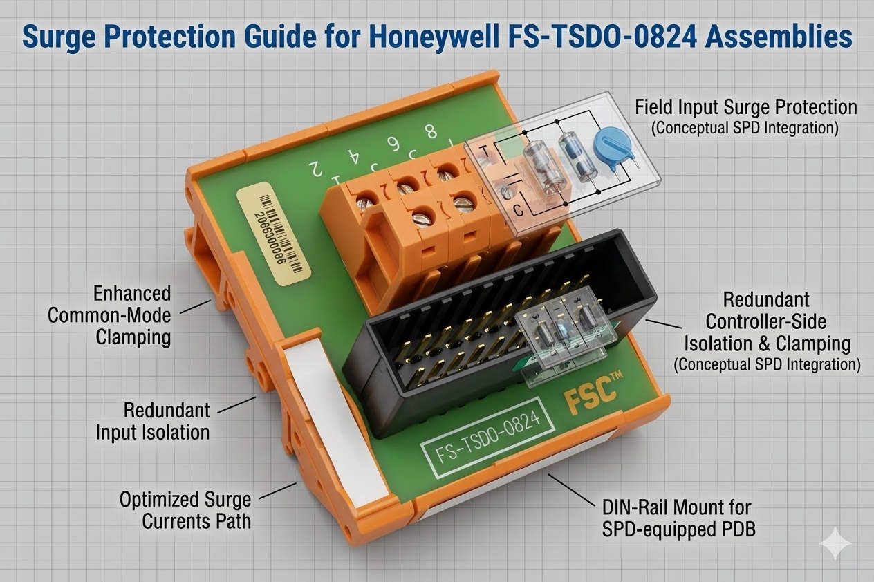
The Honeywell FS-TSDO-0824 serves as a critical interface for digital output signal termination. In high-stakes environments like petrochemical plants and offshore platforms, signal integrity remains paramount. This termination assembly ensures stable communication between safety controllers and field actuators. However, the unit does not feature built-in surge suppression modules by default. Engineers must therefore evaluate external protection strategies to safeguard expensive I/O hardware from electrical transients.
Surge Protection Guide for Honeywell FS-TSDO-0824 Assemblies

Surge Protection Guide for Honeywell FS-TSDO-0824 Assemblies

The Vital Role of Surge Mitigation in Process Automation

In modern industrial automation, transient voltage spikes represent a significant threat to control system uptime. Lightning strikes or large motor switching operations often induce high-energy surges into field wiring. These events can cause immediate hardware destruction or latent insulation degradation. Adding external Surge Protection Devices (SPD) effectively shields the FS-TSDO-0824 from inductive kickback. Consequently, facility managers see a marked reduction in unplanned shutdowns and hardware replacement costs.

Technical Considerations for External SPD Integration

Successful SPD integration requires more than just physical installation. Engineers must verify that the clamping voltage aligns with the digital output card’s tolerance. Moreover, leakage current from the SPD must remain below the field device’s threshold. High leakage can lead to “false-on” states, where valves fail to close during safety demands. Based on industry reports from MarketsandMarkets, the demand for high-reliability surge suppression is growing at a CAGR of over 5% due to increasingly sensitive electronic components.

Optimizing Grounding Infrastructure for Transient Suppression

Surge protection effectiveness depends heavily on the quality of the grounding architecture. A high-impedance ground path renders even the most advanced SPD useless. In Honeywell safety cabinets, installers should prioritize short, direct grounding conductors. Ideally, these leads should measure less than 0.5 meters. Furthermore, separate instrument grounds from power grounds to prevent noise injection. According to IEC 61643 standards, maintaining low grounding impedance is essential for diverting transient currents safely away from the FS-TSDO-0824 channels.

Managing Inductive Loads and Back-EMF Challenges

Digital outputs frequently drive inductive components like solenoid valves and interposing relays. When these loads de-energize, they generate a reverse electromotive force (Back-EMF) spike. Without proper suppression, these spikes erode relay contacts and stress electronic drivers. For DC systems, flyback diodes or TVS suppressors provide excellent protection. For AC circuits, RC snubber networks effectively reduce arcing. Implementing these layered defenses extends the operational lifespan of the termination assembly significantly.

Expert Recommendations from Powergear X Automation Limited

At Powergear X Automation Limited, we believe surge protection is a non-negotiable insurance policy for outdoor field wiring. Our field experience indicates that most I/O failures in coastal refineries stem from inadequate transient management. We recommend installing SPDs at the cabinet entry point to intercept surges before they reach internal modules. While the initial investment may seem high, the long-term savings in MTTR (Mean Time To Repair) provide a clear return on investment for any factory automation project.

Selection Guide and Practical Implementation Steps

When selecting surge protection for the FS-TSDO-0824, follow these critical steps:

  • ✅ Identify the signal voltage level (typically 24VDC for Safety Manager outputs).
  • ✅ Verify the hazardous area classification (Ex-i or non-sparking requirements).
  • ✅ Ensure the SPD response time is fast enough to protect high-speed digital logic.
  • ✅ Choose DIN-rail mounted units for easier maintenance and status monitoring.

Industrial Solution Scenarios

  • Refinery Tank Farms: Long-distance outdoor cables are highly susceptible to lightning; SPDs are mandatory here.
  • Chemical Loading Stations: Frequent motor and pump starts create high electrical noise; layered suppression prevents signal jitter.
  • Offshore Platforms: The saline environment increases corrosion; use SPDs with hermetically sealed housings and reliable status indicators.

Frequently Asked Questions (FAQ)

Q: Does adding an external SPD affect the SIL rating of a safety loop?
Technically, adding components can affect loop calculations. However, most passive SPDs have negligible failure rates. You should consult your safety functional engineer to ensure the SPD does not introduce unacceptable delay or leakage into the loop.

Q: How often should we inspect surge protectors on Honeywell systems?
We recommend an annual visual inspection and a continuity check after every major thunderstorm season. If the MOV (Metal Oxide Varistor) indicator shows thermal discoloration, replace the module immediately to maintain protection.

Q: Can I use one SPD for multiple digital output channels?
No, this is not recommended. Each output channel should have its own dedicated protection path to prevent cross-talk and ensure that a fault in one field device does not compromise the entire termination assembly.

Discover more technical solutions and high-quality parts at the official Powergear X Automation Limited website for your next project.

5 Critical Zones Where Surge Barriers Prevent Costly Plant Downtime

5 Critical Zones Where Surge Barriers Prevent Costly Plant Downtime

Introduction

Power surges are silent killers in industrial plants. They can destroy equipment in seconds, causing hours of downtime and huge losses. Surge barriers act like shields for your machines. They block dangerous voltage spikes before damage happens. This article shows you five key areas where surge barriers are non-negotiable for plant safety and uptime. Protect your bottom line by securing these critical zones today.

5 Critical Zones Where Surge Barriers Prevent Costly Plant Downtime

1. Main Power Distribution Panels

Where outside power enters your plant, surges first strike. Lightning strikes or grid issues send huge spikes through these panels. Without protection, entire production lines can fry. Unique Insight: Most plants protect main panels, but forget secondary distribution points. Double-check all entry-level panels!

2. PLC Control Cabinets

PLCs are the brains of your operation. Even small voltage spikes corrupt programs or kill I/O cards. Downtime here stops everything. Unique Insight: Surges travel through sensor wires too. Use multi-path surge barriers that protect power AND data lines entering PLC cabinets.

5 Critical Zones Where Surge Barriers Prevent Costly Plant Downtime

3. VFD and Motor Drive Systems

Variable Frequency Drives (VFDs) control motors and pumps. Surges cause mysterious “trips” or permanent damage. Replacing VFDs costs thousands and halts production. Unique Insight: During motor deceleration, VFDs create internal surges. Your surge barrier must handle both external AND self-generated spikes.

4. SCADA Network Connections

Your monitoring system uses sensitive Ethernet/RS485 links. Voltage spikes on network cables destroy switches and servers. Lost data means blind operations. Unique Insight: Fiber optic lines ignore surges! Use surge-protected media converters where copper meets fiber for “double-shield” security.

5 Critical Zones Where Surge Barriers Prevent Costly Plant Downtime

5. Critical Sensor Circuits

Flow meters, pressure transmitters, and temperature sensors feed vital data. Surges make them report wrong values or fail silently. This causes safety risks and bad product batches. Unique Insight: 4-20mA sensors need isolated surge barriers. Standard protectors can distort signals and ruin measurements.

Don’t Wait for Disaster to Strike

Surge damage is 100% preventable. The five zones above are your frontline defense. Ignoring them risks costly downtime, safety incidents, and equipment replacement. Modern surge barriers pay for themselves in one avoided shutdown.

Ready to protect your plant? Powergear X Automation Limited engineers industrial-grade surge barriers for these critical zones. Our solutions stop voltage spikes without interrupting operations.

ModelTitleLink
K-LB-2.30Pepperl+Fuchs Surge Protection BarrierLearn More
K-LB-2.30GPepperl+Fuchs Surge Protection BarrierLearn More
K-LB-1.30GPepperl+Fuchs Surge Protection BarrierLearn More
K-LB-2.6Pepperl+Fuchs Surge Protection Barrier (2 Channel)Learn More
K-LB-1.30Pepperl+Fuchs Surge Protection BarrierLearn More
Back to Top
Product has been added to your cart