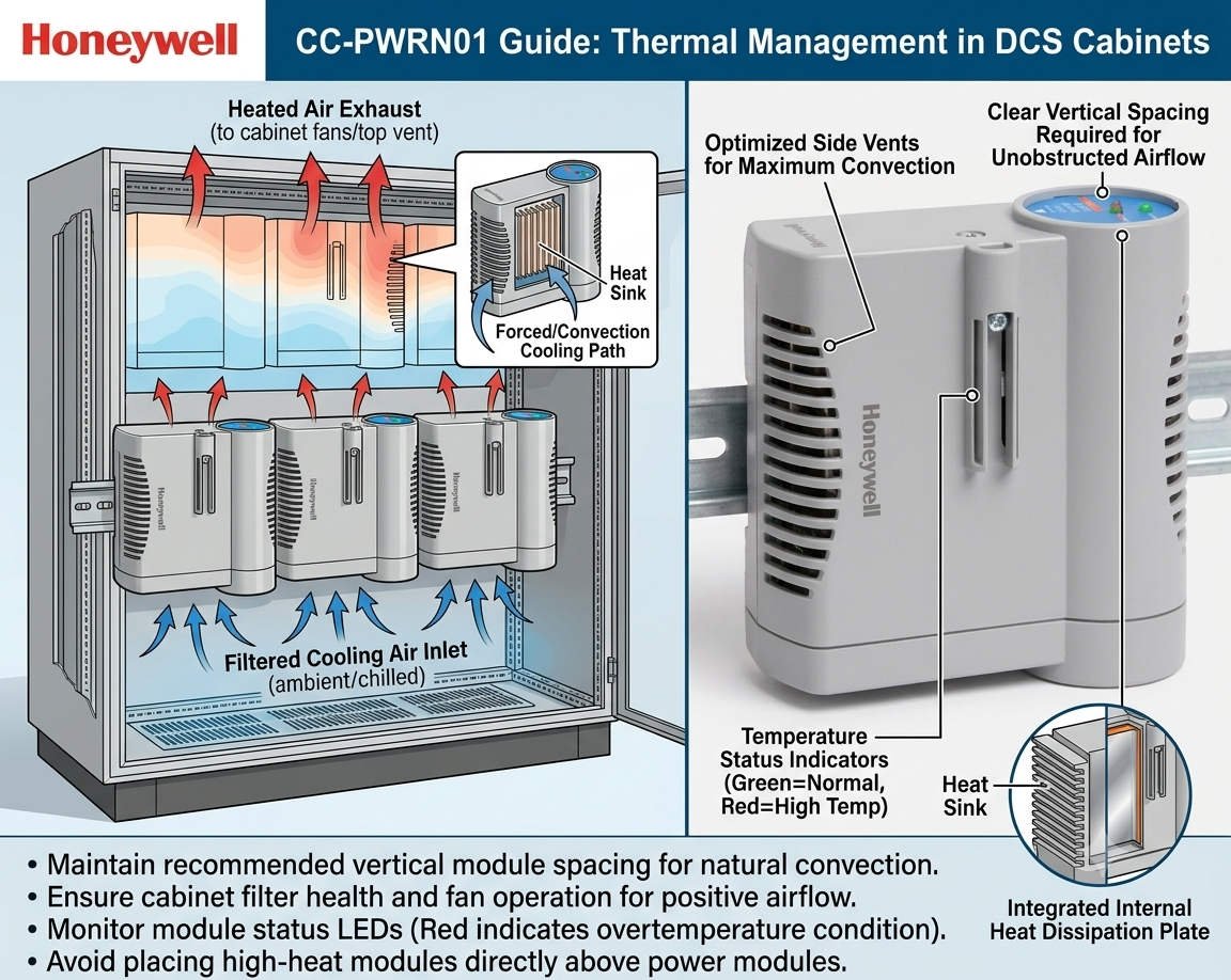
Honeywell CC-PWRN01 Guide: Thermal Management in DCS Cabinets
Ensuring DCS Stability: Thermal Management for the Honeywell CC-PWRN01 Power Module
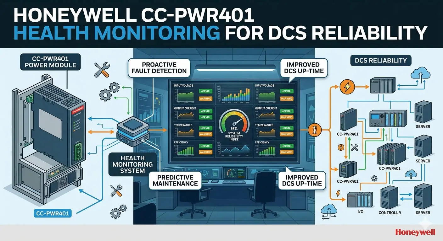
The Critical Role of Reliable Power in Industrial Automation
The Honeywell CC-PWRN01 power module provides essential redundant energy to modern Distributed Control Systems (DCS). It secures continuous operations in demanding sectors like oil, gas, and pharmaceutical production. However, system reliability depends heavily on proper thermal management. Overheating remains a leading cause of premature component failure in industrial environments. Therefore, engineers must prioritize vertical installation spacing to maintain long-term system health.

Honeywell CC-PWRN01 Guide Thermal Management in DCS Cabinets
Optimizing Vertical Spacing for Natural Convection
For the CC-PWRN01, maintaining a vertical clearance of 50–75 mm is vital for air circulation. Natural convection moves heat from the bottom to the top of the cabinet. If you obstruct this flow, internal temperatures may exceed the +70°C design limit. Moreover, restricted airflow significantly shortens the lifespan of sensitive electrolytic capacitors. In our experience, tight spacing creates hot spots that sit 15°C above the ambient cabinet temperature.
Managing Load Capacity to Reduce Heat Generation
Power modules generate substantially more heat when operating at peak capacity. Continuous high-load conditions accelerate the aging process of internal electronics. As a result, the risk of cascading failures in redundant configurations increases. At Powergear X Automation, we suggest designing systems for 60–70% of the nominal load. This conservative approach provides a safety buffer during seasonal temperature spikes or ventilation issues.
Adapting Cabinet Ventilation for Harsh Climates
The CC-PWRN01 typically relies on passive cooling within the control cabinet. Sealed or high-IP-rated enclosures require even larger spacing to prevent heat accumulation. In regions like the Middle East or Southeast Asia, ambient heat demands stricter standards. We frequently increase vertical spacing to ≥80 mm for these high-temperature projects. Furthermore, integrating heat exchangers or fan trays becomes mandatory when passive cooling reaches its physical limits.
Installation Best Practices for Power Modules
Proper physical placement ensures that heat does not affect other critical system components. Engineers should always stack power modules vertically to align with natural airflow. Additionally, avoid placing sensitive controllers or I/O processors directly above a heat-generating power supply. We once resolved recurring communication faults in a refinery by simply relocating a controller away from a module’s heat path. These small adjustments prevent significant thermal stress on the entire DCS architecture.
Routine Maintenance and Thermal Inspection Strategies
Regular inspections keep your factory automation system running at peak efficiency. Use infrared thermometers to measure the surface temperature of the CC-PWRN01 during operation. If surface readings exceed 65°C, you must immediately investigate airflow obstructions or spacing issues. Moreover, dust accumulation can reduce heat dissipation efficiency by up to 20%. Therefore, cleaning internal components during scheduled shutdowns is a simple yet effective reliability strategy.
Professional Insights from Powergear X Automation
At Powergear X Automation, we believe that thermal design is as important as electrical wiring. Modern power modules like the CC-PWRN01 are highly efficient, but they still follow the laws of thermodynamics. Neglecting a few centimeters of space can lead to millions in lost production due to an unexpected trip. We recommend a comprehensive thermal audit for every cabinet upgrade to ensure modern hardware performs within its optimal environment.
Technical Installation Checklist
- Maintain a minimum of 50–75 mm vertical clearance between units.
- Mount modules vertically to support natural bottom-to-top airflow.
- Use perforated cable ducts to avoid trapping heat near the module.
- Avoid tight cable bundling directly above the power supply vents.
- Verify that the total load stays under 75% for unventilated cabinets.
Industrial Application Scenarios
- Offshore Platforms: Maintaining redundant power in compact, high-ambient-temperature control rooms.
- Chemical Processing: Preventing thermal-induced shutdowns in sealed cabinets protected from corrosive gases.
- Pharmaceutical Batching: Ensuring high-availability power for critical sequence controllers during long production cycles.
Expert FAQ: CC-PWRN01 Implementation
Q1: How do I verify if my current cabinet spacing is sufficient?
If your vertical spacing is ≥50 mm and the cabinet interior stays below 40°C under full load, your setup is generally safe. However, if you notice the module shell feels excessively hot to the touch, consider increasing the gap to 80 mm or adding an exhaust fan to the cabinet roof.
Q2: Can I replace legacy Honeywell power supplies with the CC-PWRN01 directly?
While they are often mechanically compatible, never skip a thermal audit. Newer modules might have higher power densities and different heat profiles than 20-year-old units. Ensure the existing cabinet layout can handle the heat dissipation of the new module before finalizing the retrofit.
Q3: What are the signs of a power module failing due to heat?
Look for discolored plastic housing, bulging capacitors visible through the vents, or frequent “redundancy lost” alarms. If you detect a sweet or burnt smell during a cabinet inspection, the module is likely overheating and requires immediate replacement to avoid a total system failure.
For more technical guides and high-quality automation components, visit Powergear X Automation today.