Over 50,000 hot-selling automation module components.
Bently Nevada 3500-42M Bypass LED Issue Proximitor Wiring Guide_

Bently Nevada 3500/42M Bypass LED Issue: Proximitor Wiring Guide

Why Reverse Proximitor Wiring Illuminates the Bypass LED on Bently Nevada 3500/42M Modules

Precision machinery protection requires dependable sensors and advanced control systems in industrial automation. The Bently Nevada 3500/42M Proximity/Seismic Monitor module measures shaft vibration and displacement on critical turbomachinery. However, reversing polarity on eddy current Proximitor sensors creates unexpected behavior. The module activates the Bypass LED while the Alert LED remains dark. At Powergear X Automation, our technical team analyzes why polarity errors disrupt monitoring channels and explains how field engineers can resolve this issue efficiently.

Bently Nevada 3500-42M Bypass LED Issue Proximitor Wiring Guide_

Bently Nevada 3500-42M Bypass LED Issue Proximitor Wiring Guide_

The Core Role of Eddy Current Sensors in Machinery Protection

Rotating machinery in power generation and chemical plants relies on eddy current probes for real-time condition monitoring. The Proximitor sensor drives high-frequency radio signals through the probe tip to form an electromagnetic field. As the metal shaft moves, eddy current losses change the probe impedance. The Proximitor converts this impedance shift into a proportional DC voltage. The 3500/42M module processes this analog voltage to calculate shaft vibration amplitudes. Proper sensor operation allows plant operators to detect bearing wear and rotor unbalance before catastrophic failures happen.

Understanding the Impact of Reversed -24VDC Supply Polarity

Bently Nevada 3300 XL and 3500 proximity probe systems require a stable -24VDC power supply. Reversing terminal connections halts the internal active electronics within the Proximitor. Consequently, the sensor fails to produce a valid dynamic signal or a stable DC gap voltage. The output voltage floats near zero or clamps to an invalid rail level. B2B engineers must realize that the 3500/42M module cannot calculate real vibration data without a proper gap voltage. Therefore, the monitor inhibits alarm processing to prevent false plant trips.

Analyzing 3500/42M Bypass State Logic and Safety Design

The 3500/42M monitor features sophisticated onboard diagnostics rather than simple signal threshold detection. When an invalid input voltage occurs, internal logic marks the channel as Not OK. The monitor then suppresses alarm outputs and illuminates the Bypass LED. Field personnel often misinterpret this Bypass light as a software override. However, the system automatically enters this protective state when sensor signals fall outside valid operating ranges. This safety design ensures that unpowered or incorrectly wired sensors do not trigger accidental machine shutdowns.

Complete Diagnostic Checklist for Bently Nevada Channel Alerts

Illuminating the Alert LED on a 3500/42M module requires satisfying five distinct monitoring conditions in sequence:

  • Correct Power Supply: The Proximitor must receive a steady -24VDC supply with correct polarity.
  • Valid Gap Voltage: The probe must operate within its linear range, typically producing -8VDC to -10VDC at nominal gap.
  • Healthy Channel Status: The 3500/42M module must register a Channel OK condition in internal memory.
  • Active Alarm Logic: Software configuration must enable channel alerts without manual user bypass.
  • Vibration Threshold Exceeded: Shaft vibration amplitude must exceed the programmed alert setpoint value.

Step-by-Step Commissioning and Troubleshooting Sequence

Engineers should follow a structured sequence when troubleshooting a Channel Not OK or active Bypass status:

  1. Verify Terminal Wire Definitions: Confirm connections at Terminal A (-24VDC), Terminal B (COM), and Terminal C (Signal OUT) instead of relying solely on wire colors.
  2. Measure Static Gap Voltage: Use a digital multimeter to measure DC voltage across COM and OUT terminals at the field junction box.
  3. Inspect System Event Logs: Connect via 3500 Rack Configuration Software to check for specific fault messages like Input Voltage Fault.
  4. Clear Software Bypass Overrides: Ensure maintenance teams clear all manual software bypass flags after completing field wiring corrections.

Field Installation Best Practices and Cable Shielding Rules

High-vibration machinery environments present severe electromagnetic noise from variable frequency drives and high-power motors. Signal cables must utilize twisted-pair construction with overall shielding. Engineers must connect the cable shield to ground at the control cabinet end only. Dual-ended shield grounding creates circulating earth loops, which introduce artificial electrical noise onto the -24VDC supply lines. Proper wiring practices protect delicate proximity signals and prevent false vibration alarms across factory automation networks.

B2B Procurement and Hardware Replacement Guidelines

Replacing legacy Bently Nevada Proximitors requires verifying technical specifications rather than assuming direct hardware equivalence. Procurement specialists must match probe diameters, system lengths, and scale factors. For example, mixing 5mm probes with 8mm Proximitor drivers shifts the output scale factor from 7.87 mV/um to incorrect levels. Modern 3300 XL components maintain backward compatibility with older 3500 racks, but engineers must verify system calibration in the 3500 software prior to commissioning.

Application Scenario: Gas Turbine Vibration Monitoring Circuit

During a scheduled overhaul on a 50MW gas turbine, technicians installed new 3300 XL 8mm proximity probes on the main bearing housings. Upon powering up the control cabinet, the 3500/42M module displayed solid Bypass LEDs on channels 1 and 2, while the Alert LEDs remained completely unlit. The maintenance team initially suspected damaged 3500/42M input cards.

However, field diagnostic checks revealed that contractors had transposed the -24VDC power supply and Signal OUT conductors at the intermediate junction box. Restoring proper terminal polarity allowed the Proximitors to establish a stable -9.2VDC gap voltage. The 3500/42M module automatically cleared the Channel Not OK state, extinguished the Bypass LED, and activated normal machinery protection without requiring hardware replacement.

For genuine machinery protection hardware and technical support on Bently Nevada components, visit Powergear X Automation to source certified control system modules for your facility.

Frequently Asked Questions (FAQ)

Q1: Does reversing -24VDC polarity permanently damage a Bently Nevada Proximitor?
Usually no. Bently Nevada Proximitors include reverse-polarity protection diodes designed to withstand short-term wiring errors. However, prolonged exposure to incorrect voltages or excessive power supply currents can cause internal component degradation.

Q2: Why does the 3500/42M module show a Bypass LED instead of a red Fault LED?
The Bypass LED indicates that the monitor is inhibiting its relay and alarm outputs for that channel. An invalid signal from a reversed Proximitor causes the system to automatically enter bypass mode to prevent false plant trips.

Q3: Do I need to recalibrate the 3500/42M rack after replacing a Proximitor sensor?
If you replace the sensor with an identical part number and matching cable length, full recalibration is not required. However, you must verify the DC gap voltage in the 3500 Rack Configuration Software to confirm correct mechanical installation.

Bently Nevada 3500-42M 140734-02 Grounding Best Practices_

Bently Nevada 3500/42M 140734-02 Grounding Best Practices

Eliminating 50Hz Interference: Grounding the Bently Nevada 3500/42M 140734-02

Understanding Grounding Challenges in Control Systems

The Bently Nevada 3500/42M Proximitor/Seismic Monitor, utilizing the 140734-02 rear I/O, is a staple in industrial automation. However, engineers often face 50Hz power frequency interference that triggers false vibration alarms. We observe that these issues frequently stem from improper COM and safety ground management. Maintaining signal integrity requires precise grounding techniques to ensure accurate data within your DCS or PLC infrastructure.

Bently Nevada 3500-42M 140734-02 Grounding Best Practices_

Bently Nevada 3500-42M 140734-02 Grounding Best Practices_

The Role of the COM Terminal

Many technicians mistakenly bond the COM terminal to multiple plant grounding points. The COM terminal acts as a signal reference, not a protective earth. Connecting it to several locations creates ground loops that inject 50Hz noise into your vibration signals. This interference degrades measurement accuracy and compromises your factory automation monitoring performance. You must keep the COM terminal isolated from the safety ground path to prevent circulating currents.

Implementing Single-Point Grounding

Industry standards, including API 670 guidelines, recommend a single-point grounding strategy for signal commons. This approach forces all return currents through one controlled path. Follow these steps to optimize your installation:

  • Identify one designated grounding point inside your control cabinet.
  • Connect the signal common to this point only.
  • Ensure the cabinet ground bar links directly to the plant safety ground.
  • Route sensor cables away from high-current power conductors.
  • Verify that shields terminate correctly according to manufacturer specifications.

Strategic Insights from Power Gear X Automation Limited

Based on our field experience, approximately 75% of noise-related issues result from poor shielding rather than hardware defects. Before replacing your 3500/42M module, perform a thorough inspection of your cabling. Check for electromagnetic interference (EMI) near VFDs and large motors. If you continue to see stable 50Hz peaks across multiple channels, your grounding topology likely requires a professional review. For expert support or authentic Bently Nevada components, please visit Power Gear X Automation Limited.

Troubleshooting and Best Practices

  • ⚙️ Measure AC voltage potential between the cabinet and machine frame.
  • 🔧 Isolate shield connections during testing to identify ground loop sources.
  • ✅ Use high-quality shielded twisted-pair instrumentation cables for all sensors.
  • ⚙️ Install galvanic isolation for sensors located over 100 meters away.
  • 🔧 Inspect all terminal block connections for corrosion or loose wires.

Frequently Asked Questions

Q1: How can I distinguish electrical interference from mechanical vibration faults?
Electrical noise usually presents as a constant 50Hz frequency peak across multiple channels. Mechanical faults typically track with the machine’s running speed. If the noise disappears when you isolate the cable shield, the issue is almost certainly grounding-related.

Q2: Why does my vibration reading fluctuate when a nearby motor starts?
This indicates electromagnetic coupling or a ground loop issue. Large motors generate significant EMI. If your signal cables lack proper shielding or run parallel to motor power lines, the monitor will pick up induced noise during high-load operations.

Q3: Should I always replace the 140734-02 module when I see 50Hz noise?
Replacement is rarely the first solution. Our team at Power Gear X Automation Limited suggests performing a systematic grounding audit first. Hardware failure in the 3500 system is uncommon compared to environmental and installation-related signal corruption.

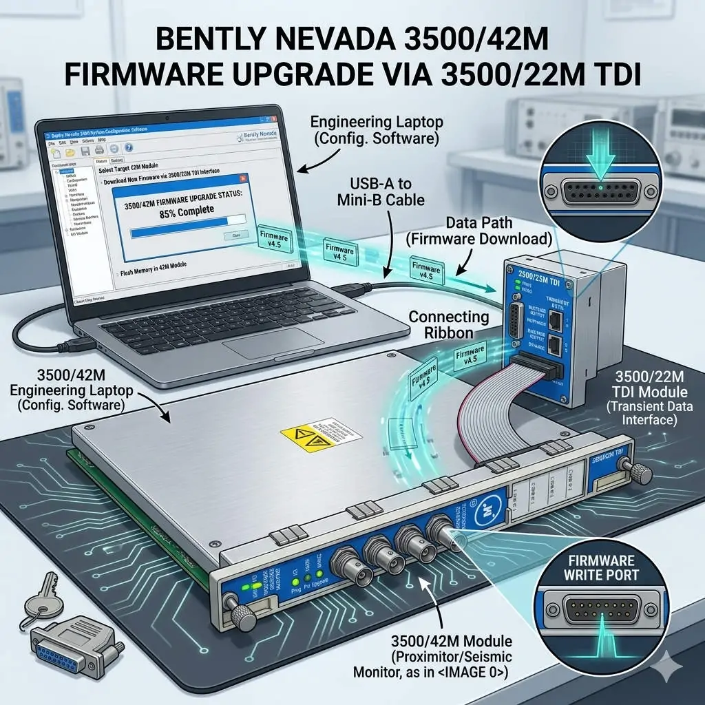
Bently Nevada 3500-42M Firmware Upgrade via 3500-22M TDI

Bently Nevada 3500/42M Firmware Upgrade via 3500/22M TDI

Seamless Firmware Upgrades for 3500/42M via the 3500/22M Communication Module

Enhancing Reliability in Machinery Protection Systems

In the world of industrial automation, maintaining firmware consistency is vital for system health. The Bently Nevada 3500 series represents the gold standard for machinery protection. Specifically, the 3500/42M Proximitor/Seismic Monitor requires precise firmware to deliver accurate vibration diagnostics. By utilizing the 3500/22M Transient Data Interface (TDI) as a gateway, engineers can perform updates remotely. This method eliminates the need to remove hardware from the rack, ensuring continuous mechanical integrity.

Bently Nevada 3500-42M Firmware Upgrade via 3500-22M TDI

Bently Nevada 3500-42M Firmware Upgrade via 3500-22M TDI

Understanding the TDI Communication Gateway Architecture

The 3500/22M module serves as the primary bridge between the rack backplane and configuration software. It manages data traffic for both Ethernet and serial connections. During a firmware flash, the TDI module receives data packets and distributes them to the targeted 3500/42M monitor. This centralized architecture simplifies maintenance in complex factory automation environments. However, a stable network link is mandatory. Consequently, any communication dropout during the process could potentially corrupt the module memory.

Navigating Firmware Compatibility and Revision Control

Strict revision control defines successful Bently Nevada system management. Each monitor module must align with the rack’s overall firmware version. Mismatched versions often cause channel misinterpretation or alarm logic failures. Moreover, the configuration software version must support the specific firmware build. Powergear X Automation Limited experts recommend consulting the official “Firmware Compatibility Matrix” before starting. This proactive step prevents communication instability and ensures the DCS or PLC receives accurate data.

Strategic Scheduling for System Availability

Upgrading a single module typically takes between three and ten minutes. During this window, the 3500/42M module stops monitoring active vibration signals. This creates a temporary “blind spot” for critical rotating equipment like turbines or compressors. Therefore, engineers should only initiate upgrades during planned maintenance windows. Alternatively, perform updates while the machinery is in a standby state. Proper planning protects the assets while the control systems receive necessary security and feature patches.

Operational Best Practices for Safe Flashing

Field experience suggests that power stability is the most critical factor during firmware transfer. Voltage fluctuations can interrupt the write process and “brick” the hardware. In addition, avoid using high-latency connections like VPNs for firmware tasks. Local direct-cable connections offer the highest success rate. While the 3500 system supports hot-swapping, you must never reseat a module during an active flash. Following these technical guidelines ensures the longevity of your industrial hardware investment.

Industry Standards and Technical Insights

According to reports, the global machinery monitoring market is shifting toward digitalized maintenance. Standardizing firmware across your plant enhances diagnostic accuracy and audit readiness. For regulated sectors like petrochemicals, maintaining validated firmware levels is essential for compliance. At Powergear X Automation Limited, we believe that staying current with firmware is a cost-effective way to unlock advanced vibration analysis features without replacing physical modules.

Application Scenarios and Solutions

  • Oil & Gas Refineries: Use the 3500/22M to update monitors across large-scale compressor stations without entering hazardous zones.
  • Power Generation: Ensure turbine protection modules have the latest patches for improved transient data capture during start-up.
  • Water Treatment: Maintain high availability by upgrading backup pump monitors during low-demand periods.

Technical Execution Checklist

  • ✅ Verify the 3500/22M TDI is online and stable in the configuration software.
  • ✅ Confirm the target 3500/42M module slot is correctly identified.
  • ✅ Ensure the rack power supply is connected to a reliable UPS.
  • ✅ Back up the existing rack configuration before initiating any firmware changes.
  • ✅ Validate the module status and reload the configuration after the update finishes.

Expert Frequently Asked Questions

Q: Will my existing configuration be lost after a firmware upgrade?
Generally, the configuration remains, but firmware changes can sometimes alter memory mapping. We always recommend saving a copy of the rack configuration to your PC. After the upgrade, verify that all setpoints and delay timings remain unchanged.

Q: Can I upgrade multiple 3500/42M modules simultaneously?
Most configuration software allows for sequential updating. However, upgrading modules one by one is safer. This approach limits the “blind spot” to a single monitoring group at any given time, maintaining better overall rack protection.

Q: What should I do if the upgrade progress bar freezes?
Do not cycle power immediately. Wait at least 15 minutes to ensure no background processes are active. If the module remains unresponsive, check the TDI communication status. You may need to perform a “bootloader” recovery if the primary firmware image is corrupted.

For high-quality modules and expert technical support, visit the official Powergear X Automation Limited website to secure your system components.

Choosing BN 3500 Modules for Industrial Vibration Monitoring

Choosing BN 3500 Modules for Industrial Vibration Monitoring

Choosing the Right Bently Nevada Monitor: 3500/40M vs. 3500/42M for Industrial Automation

Selecting the optimal machinery protection module is vital for system reliability in industrial automation environments. Bently Nevada’s 3500 series offers two primary choices for vibration monitoring: the 3500/40M Proximitor® Monitor and the 3500/42M Proximitor®/Seismic Monitor. Although both are cornerstones of a robust control systems setup, their capabilities and ideal applications differ significantly. Understanding these distinctions ensures you select the best fit for your factory automation needs.

Choosing BN 3500 Modules for Industrial Vibration Monitoring

The Specialized Focus of the 3500/40M Proximitor Monitor

The 3500/40M, a four-channel monitor, maintains a precise and focused application scope. It exclusively manages input from proximity probes (Proximitors). This design targets machines where shaft movement relative to the bearings or housing is the most critical measurement. We primarily see the 40M utilized in high-speed turbomachinery, such as steam and gas turbines, or critical large compressors. It excels at measuring:

  • Shaft Relative Vibration: Detecting radial movement of the rotating shaft.
  • Shaft Position: Monitoring axial (thrust) position.
  • Keyphasor Signals: Providing critical phase reference for diagnostic analysis.

This module is a gold standard where the protection strategy hinges entirely on relative shaft vibration measurements, a common practice in API 670 compliance for critical assets.

Expanded Versatility with the 3500/42M Proximitor/Seismic Monitor

The 3500/42M offers a much broader set of features, reflecting its dual-purpose design. It is also a four-channel module, but its key differentiator is the flexibility in sensor input. The 42M accepts not only proximity probes but also seismic sensors. This makes it suitable for equipment requiring both shaft and casing vibration monitoring simultaneously.

The 42M can measure:

  • Shaft Relative Vibration and Position (using Proximitors).
  • Casing Absolute Vibration (using velocity or acceleration transducers).

Therefore, the 42M module is a preferred choice for monitoring “balance-of-plant” equipment. This includes motors, pumps, fans, and gearboxes, assets that often require casing vibration monitoring for condition assessment. Moreover, the ability to mix sensor types within a single module significantly simplifies the PLC or DCS I/O integration.

Key Technical Differences: Sensor Compatibility and Measurement Scope

The primary technical divergence lies in the sensor compatibility, which directly dictates the module’s application scope.

  • The 3500/40M is limited to Proximitor inputs. Consequently, its measurements are inherently relative to the sensor mount.
  • However, the 3500/42M supports a mixed configuration. It handles Proximitor, seismic velocity, and seismic acceleration sensors.

This flexibility allows the 42M to deliver both relative (shaft) and absolute (casing) vibration readings, providing a more comprehensive view of machine health. In addition, the 42M’s advanced signal processing adapts easily to the different dynamics of various sensor types, offering a more versatile tool for maintenance engineers.

Application Scenarios: Turbomachinery vs. General-Purpose Machinery

The selection between the 40M and 42M often comes down to the machinery type and criticality.

  • 3500/40M for Critical Turbomachinery: When monitoring large, critical assets like turbines or hydrogen compressors, the protection philosophy focuses on preventing contact between the shaft and stationary parts. The 40M provides the precise, dedicated proximity measurements needed.
  • 3500/42M for Flexible Monitoring: For general-purpose machinery, such as an ANSI pump or a cooling tower fan, casing vibration provides sufficient data for condition monitoring. The 42M offers an economical, multi-sensor solution for these assets, consolidating diverse inputs into one industrial automation rack.

Author’s Insight: From a system design perspective, I believe the 42M offers superior long-term value in an expanding plant. While the 40M is perfect for pure API 670 compliance on a turbine, the 42M is far more future-proof. It allows the plant to easily integrate new sensor types (like accelerometers for gearbox fault detection) without adding an entirely new monitoring chassis.

Choosing the Right Module: A Practical Decision Matrix

Consider these practical points before making your final selection:

Choose the 3500/40M if:

  • Your equipment is critical, high-speed turbomachinery.
  • You require pure proximity measurements (shaft vibration, thrust).
  • API 670 compliance based on relative vibration is the main goal.

Choose the 3500/42M if:

  • You need to monitor both shaft and casing vibration.
  • The system requires mixed sensors (e.g., proximity for thrust, velocity for bearing caps).
  • Your plant has many different machinery types (pumps, motors, fans, gearboxes).
  • You prioritize flexibility and consolidation of inputs.

In summary, the 40M is specialized for high-fidelity shaft monitoring, while the 42M is the Swiss Army knife of general-purpose machinery protection.

Technical Power Features of the 3500/42M

The 3500/42M’s added capabilities provide significant operational advantages in complex control systems:

  • Compatibility: Accepts 2-wire and 3-wire proximity probes, velocity sensors, and accelerometers.
  • Mixed Monitoring: Capable of combining different sensor types within the four channels.
  • Enhanced Diagnostics: Supports both absolute (casing) and relative (shaft) vibration analysis.

As a result, the 42M provides a richer data set for predictive maintenance strategies.

Solution Scenario: Gearbox Monitoring

Consider a gearbox paired with a large motor.

  • Motor Monitoring: A 3500/42M channel can monitor casing vibration on the motor using a velocity sensor.
  • Gearbox Monitoring: The same 42M module can use an accelerometer to detect high-frequency gear mesh faults.
  • Thrust Protection: An additional channel can use a proximity probe to monitor the gearbox input shaft’s thrust position.

This single 3500/42M module delivers comprehensive protection and condition monitoring across multiple fault modes, enhancing the overall industrial automation safety profile.

The team at Powergear X Automation Limited can assist you in selecting and integrating the ideal Bently Nevada 3500 solution for your specific application. Learn more about our comprehensive machinery protection and control system integration services by clicking here: https://www.powergearx.com/

Frequently Asked Questions (FAQ)

Q1: How does the choice impact the overall control system (PLC/DCS) integration?

A: Minimal impact on the control system itself. Both the 40M and 42M communicate with the PLC or DCS via their TMR or redundant communication modules (like the 3500/92). The main difference lies in the number of Bently Nevada racks required. If you consolidate multiple sensor types onto a 42M, you reduce the physical footprint and I/O count dedicated to machinery monitoring, potentially simplifying the factory automation system architecture.

Q2: Can I upgrade a 3500/40M to a 3500/42M?

A: No, you cannot simply upgrade the firmware or configuration. They are distinct hardware modules with different internal circuitry to handle the different sensor signal types. If your monitoring needs expand to include seismic measurements, you must purchase and install a new 3500/42M module into the rack. This is a common maintenance upgrade when migrating from solely protection-focused to combined protection and condition monitoring strategies.

Q3: Is one module more complex to configure than the other?

A: The 3500/42M requires slightly more complex configuration due to its versatility. The technician must specify the sensor type (proximity, velocity, or accelerometer) for each of the four channels, along with the correct integration and scaling settings. The 3500/40M is simpler; all channels are proximity-based, limiting the configuration options primarily to scale factors and alarm setpoints. I typically recommend the 42M only be configured by personnel experienced in machinery vibration and sensor characteristics to ensure accuracy.

Back to Top
Product has been added to your cart