Over 50,000 hot-selling automation module components.
GE RX3i vs RX7i

GE RX3i vs RX7i: A Deep Dive into PLC Differences for Industrial Automation

Understanding the PACSystems Evolution in Industrial Automation

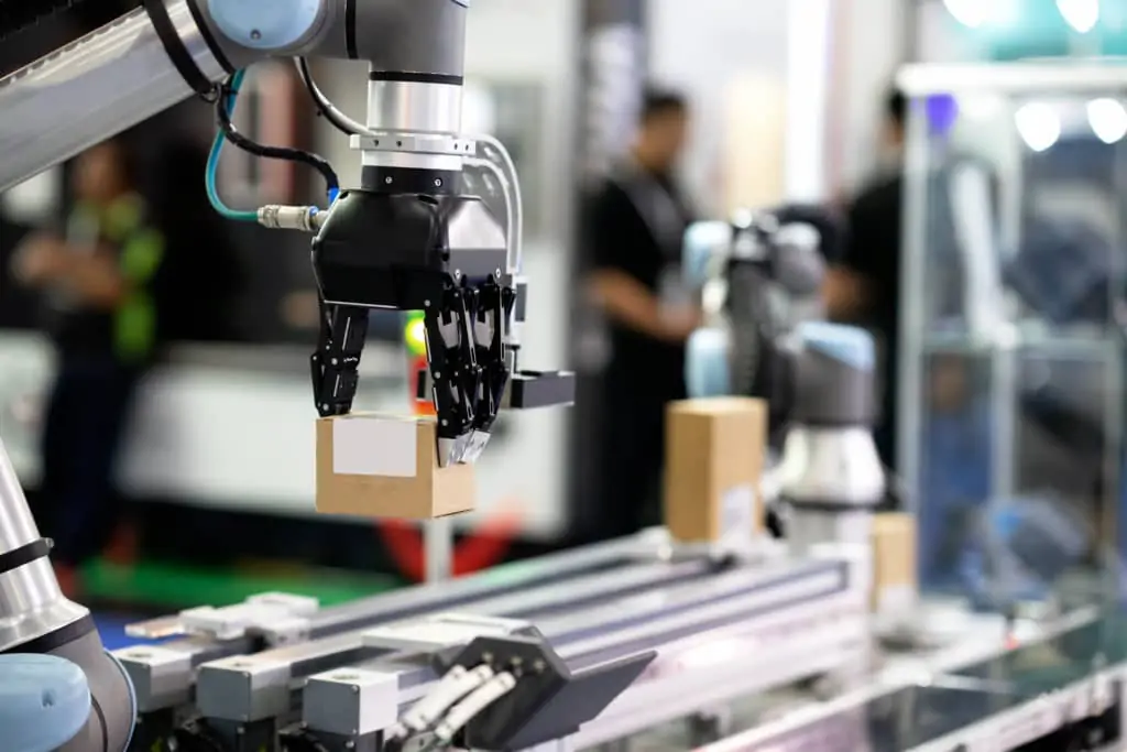
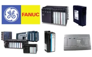
Industrial automation relies heavily on robust control systems. General Electric (GE) (now part of Emerson Electric Co. PACSystems) provided two significant platforms: the RX3i and the older RX7i. Both Programmable Logic Controllers (PLCs) managed critical factory automation tasks. Understanding the distinctions is vital for system architects and control engineers. We will explore the core differences in performance, architecture, and application.

Architectural Foundation: Bus Technology and Backplane Speed

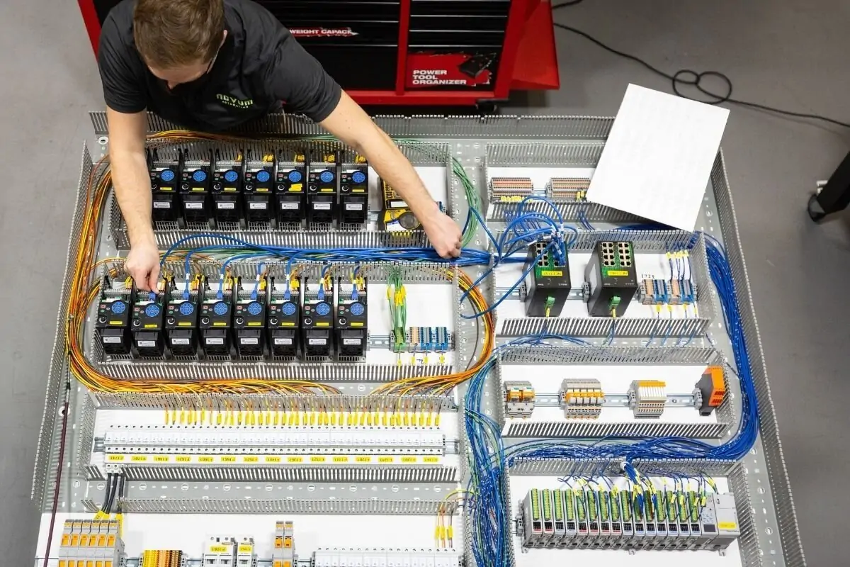
The backplane forms the communication backbone for all modules. The RX7i utilizes the older VME bus architecture. This architecture offered reliability in its time. However, the RX3i leverages the innovative PCI-Express-based Universal Backplane. This change dramatically improves data throughput and communication speed. Faster backplane communication directly enhances real-time control performance.

GE RX3i vs RX7i

Processing Power: Performance for Modern Control Systems

Modern control systems demand faster processing. The RX3i features cutting-edge, often multi-core, processors. These powerful CPUs execute complex control logic much quicker than the RX7i’s older generation processors. Moreover, the RX3i offers significantly more working memory. As a result, it handles larger data sets and sophisticated industrial automation applications easily. This speed difference is crucial for high-speed manufacturing.

Communication and Networking: Bridging the Industrial Ethernet Gap

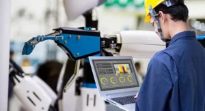
Connectivity is paramount in today’s industrial automation landscape. The RX3i often includes integrated Gigabit Ethernet and supports modern protocols like PROFINET. This facilitates high-speed data exchange across the network. Conversely, the RX7i required separate communication modules for many advanced network functions. Therefore, the RX3i simplifies network setup and enhances distributed control systems capabilities.

Form Factor and Modularity: Adapting to Factory Automation Needs

The RX7i generally employed a larger form factor due to the VME bus standards. This sometimes required more cabinet space. The RX3i offers a more compact design, often fitting better into modern, space-conscious factory automation environments. Furthermore, both platforms offer hot-swap capabilities for I/O modules. However, the RX3i’s Universal Backplane provides better future-proofing for new module technologies.

GE RX3i vs RX7i

The Author’s Insight: Choosing the Right PLC Platform

The RX7i was a workhorse, proving its reliability for decades. However, its technology is now considered legacy. The RX3i clearly offers superior performance, better communication, and a more modern architecture. We recommend new installations and major upgrades should strongly favor the RX3i series. This aligns with industry trends towards faster data processing and seamless integration with Industrial Internet of Things (IIoT) concepts. Investing in the RX3i ensures longevity and better return on investment.

Application Scenarios: Where Each System Shines

The RX7i still operates reliably in many existing plants, particularly for lower-speed processes. Companies often keep them running due to high reliability and the cost of migration. The RX3i excels in high-performance applications like high-speed packaging, complex motion control, and extensive Distributed Control System (DCS) architectures. Its capacity for large-scale data logging and analysis makes it ideal for optimization efforts.

GE RX3i vs RX7i

Elevate Your Industrial Automation Strategy with Powergear X

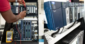
Navigating the complexities of PLC and DCS platforms is our specialty. Powergear X Automation Limited provides expert consulting, integration, and solutions using the robust PACSystems technology. Whether you are migrating from RX7i to RX3i or designing a new control systems network, our certified engineers deliver world-class service.

Ready to upgrade your industrial automation systems? Click here to explore our specialized RX3i solutions and technical support packages tailored for optimal performance.

Troubleshooting Bently Nevada 3300 NSv Metric Probe Issues

Resolving Zero Output: Troubleshooting Bently Nevada 3300 NSv Metric Probe Issues

Understanding the 3300 NSv Metric Probe

The Bently Nevada 3300 NSv Metric Probe is vital. It measures shaft vibration and position accurately. These proximity probes are essential for industrial automation systems. They monitor critical machinery health. The probe system relies on a non-contact technique. Therefore, zero output is a serious indicator of a fault. We must address this quickly to maintain machine protection.

Initial Diagnostics: Checking Power and Wiring

Start by verifying the system’s power supply. The 3300 NSv proximity system needs stable DC voltage. Check the wiring for physical damage first. Look for cuts, abrasions, or loose connections. Moreover, confirm correct polarity for the power leads. Incorrect wiring often causes a zero or unstable signal. Always consult the system’s manual for pinout specifications.

Troubleshooting Bently Nevada 3300 NSv Metric Probe Issues

Examining the Proximitor Sensor and Gap Voltage

The Proximitor Sensor is key to the system’s function. Measure the Gap Voltage at the Proximitor output terminals. A healthy system shows a specific DC voltage range. A zero reading here strongly suggests a probe or Proximitor failure. Alternatively, a short circuit in the probe cable could be the issue. Use a digital multimeter for accurate voltage measurement.

Investigating Probe and Cable Integrity

Probe damage is a common culprit. Inspect the probe tip for dirt, grease, or physical damage. Contaminants can block the electromagnetic field. The probe cable’s integrity is also crucial. Perform a resistance check on the cable and probe assembly. A high resistance reading indicates an open circuit. This issue directly leads to no output signal.

System Integration with PLC and DCS

The 3300 NSv output feeds into control systems like PLC or DCS. The zero output might originate downstream. Check the input module settings on your factory automation controller. Ensure the scaling and input type are correct for the 3300 NSv signal. Incorrect configuration prevents the controller from reading the signal. Therefore, verify software settings thoroughly.

Troubleshooting Bently Nevada 3300 NSv Metric Probe Issues

The Influence of Grounding and Shielding

Proper grounding is paramount in noisy industrial environments. Bad grounding causes signal interference or loss. Ensure the Proximitor housing is correctly grounded. Additionally, the cable shielding must be intact and correctly terminated. Good shielding prevents electrical noise from corrupting the low-level signal. This is a vital step in high-noise industrial automation.

Author’s Insight: Leveraging Modern Diagnostics

My experience suggests investing in modern diagnostic tools. Portable vibration analyzers can quickly test the probe’s health. Furthermore, trending the Gap Voltage is a powerful predictive tool. A gradual voltage shift precedes total signal loss. Bently Nevada continues to set the standard for machine protection. Proactive maintenance far outweighs reactive repairs.

Troubleshooting Bently Nevada 3300 NSv Metric Probe Issues

Application Scenario: Turbo-Machinery Monitoring

The 3300 NSv is frequently deployed on critical turbo-machinery. Imagine a compressor trip caused by a false zero-vibration reading. Downtime costs skyrocket rapidly. Regular checks of the system’s Gap Voltage prevent this scenario. A functioning proximity probe is the first line of defense in process control safety.

For reliable solutions and expert support in maintaining your industrial automation and control systems, and for high-quality replacement parts, Powergear X Automation Limited offers a wide range of products.

Click here to explore Powergear X Automation Limited‘s solutions for vibration monitoring and machine protection.

ModelTitleLink
1900/27-01Bently Nevada Vibration Monitor ModuleLearn More
60M100-00Bently Nevada Condition Monitoring SystemLearn More
3500/53 133388-01Bently Nevada Overspeed Detection ModuleLearn More
3500/45 176449-04Bently Nevada Position MonitorLearn More
3500/77M-03-00 176449-07Bently Nevada Recip Cylinder Pressure MonitorLearn More
Optimizing Vibration Monitoring with the Bently Nevada 3500 System

Optimizing Vibration Monitoring with the Bently Nevada 3500 System

Understanding the Foundation of Machine Health

Vibration monitoring is critical for asset reliability. The Bently Nevada 3500 system is a leading solution. It provides continuous monitoring of critical machinery. This helps prevent unexpected failures. The system integrates well with modern industrial automation platforms. It works with both PLC and DCS systems. This integration creates a comprehensive overview of equipment health.

Key Components for Effective Monitoring

The Bently Nevada 3500 rack is the central hub. It houses various modules. These modules include power supplies and system monitors. They also include I/O modules. The system uses proximity probes and velocity sensors. These sensors collect real-time data. Data accuracy is essential. Moreover, proper sensor installation is paramount for reliable readings.

Optimizing Vibration Monitoring with the Bently Nevada 3500 System

Leveraging Software for Proactive Insights

Effective monitoring goes beyond hardware. The 3500 system uses powerful software. This software analyzes vibration data. It identifies trends and patterns. For instance, you can spot bearing wear early. This allows for planned maintenance. The software’s capabilities enhance overall factory automation. It turns raw data into actionable insights.

Integration with Modern Control Systems

The Bently Nevada 3500 seamlessly integrates with higher-level control systems. It connects to both PLC and DCS networks. This integration is vital for synchronized operations. As a result, machine data is available to operators. Operators can make informed decisions. This connectivity improves efficiency and reduces downtime. This is a key aspect of advanced industrial automation.

Optimizing Vibration Monitoring with the Bently Nevada 3500 System

Practical Tips for System Optimization

To optimize your 3500 system, focus on calibration. Regular calibration of probes ensures data integrity. Furthermore, configure alarm setpoints carefully. Incorrect setpoints can lead to false alarms. Or, they might miss critical issues. My experience shows that proper training for operators is crucial. They must understand the data. This expertise is what turns a good system into a great one.

Application in Real-World Scenarios

A chemical plant used the 3500 system on a critical pump. The system detected a sudden rise in vibration. This alerted maintenance staff immediately. They found a misaligned shaft. The quick detection prevented a catastrophic failure. This example highlights the system’s value. It proves that proactive monitoring saves time and money. It is a fundamental tool in any modern factory automation strategy.

3300 XL 8 mm Probe System Wiring Guide for Industrial Automation

Need a customized solution for your factory?

Learn more about how the Bently Nevada 3500 system can be tailored to your specific needs. Powergear X Automation Limited offers expert guidance and top-tier solutions to help you achieve operational excellence. Explore our products and services to elevate your industrial automation capabilities.

ModelTitleLink
3500/53 133388-01Bently Nevada Overspeed Detection ModuleLearn More
3500/45 176449-04Bently Nevada Position MonitorLearn More
3500/42-09-01Bently Nevada Proximitor Seismic MonitorLearn More
3500/32-01-01Bently Nevada 4-Channel Relay ModuleLearn More
Bently Nevada 3500 System Installation: A Complete Guide for Industrial Automation

Bently Nevada 3500 System Installation: A Complete Guide for Industrial Automation

Step-by-Step Installation Guide for the Bently Nevada 3500 System

The Bently Nevada 3500 system is a cornerstone of industrial automation. It provides continuous, online monitoring of machinery. This guide provides a clear, step-by-step installation process. Following these steps ensures a reliable and accurate setup. Proper installation is critical for protecting vital plant assets.

Understanding the 3500 System’s Core Components

Before installation, understand the system’s parts. The Bently Nevada 3500 rack houses all modules. Key modules include the power supply and rack interface module. You also need vibration, thrust, and speed monitor modules. Moreover, a communication gateway module is often used. It links to your DCS or PLC via protocols like Modbus. Knowledge of these parts prevents installation errors.

Bently Nevada 3500 System Installation: A Complete Guide for Industrial Automation

Properly Mounting the 3500 Rack

First, select a suitable location for the rack. The location must be free from excessive heat and vibration. Mount the rack firmly to a sturdy surface. Use all mounting holes to ensure stability. Improper mounting can affect module performance. Therefore, a secure, level surface is non-negotiable. This step is the foundation of a reliable monitoring system.

Installing the Power Supply and Rack Interface

Next, install the power supply module. A dual power supply setup is recommended. This provides redundancy for critical applications. Then, insert the Rack Interface Module (RIM). The RIM handles all communication with the rack. It also provides system-level alarms. This module is essential for system health monitoring.

Configuring Monitor Modules and Channels

After the core modules are in place, install your monitor modules. Each module has a specific function. A 3500/42M is for proximity probes. The 3500/50 is for speed measurement. Ensure each module is in its correct slot. The Bently Nevada 3500 system uses a specific slot numbering scheme. Incorrect placement will lead to configuration problems. As a result, always follow the manual for slot assignments.

Bently Nevada 3500 System Installation: A Complete Guide for Industrial Automation

Wiring the Field Sensors and Probes

Wiring is a critical part of the process. Connect field sensors and probes to the terminal blocks. These include proximity probes, accelerometers, and thermocouples. Use proper shielded cable to prevent interference. Grounding must be done according to the manual. Bad grounding can introduce noise. Noise can corrupt data. This compromises the entire monitoring solution.

System Configuration and Software Setup

The final step is software configuration. Use the Bently Nevada 3500 System Configuration Software (SCS). This software lets you define each channel. You can set up alarm setpoints and data collection intervals. This step tailors the system to your machinery. Without proper configuration, the system cannot provide useful data. Therefore, this step is crucial for effective machine protection.

Expert Insights: Bently Nevada and Industrial Automation

The Bently Nevada 3500 system is a perfect example of modern industrial automation. It seamlessly integrates with larger factory automation systems. It is more than just a monitoring device. It’s a key component in a predictive maintenance strategy. This reduces unplanned downtime. As an engineer with experience in control systems, I’ve seen firsthand the benefits. Its reliability is unmatched. Companies can save millions by preventing catastrophic failures.

Bently Nevada 3500 System Installation: A Complete Guide for Industrial Automation

Real-World Application: Power Plant Turbine Monitoring

A common use case is monitoring gas turbines in power plants. The 3500 system monitors rotor vibration and axial position. This protects against blade rub and bearing failure. Its integration with the control system allows for automatic shutdowns. This is a critical PLC function. This level of protection is vital for high-speed, high-value assets.

Want to learn more about how we can help you with your Bently Nevada 3500 or other industrial automation needs? Our team at Powergear X Automation Limited offers comprehensive solutions.

Click below to explore our product offerings and consulting services.

ModelTitleLink
3500/42-01-00Bently Nevada Proximitor Seismic MonitorLearn More
3500/32-01-00Bently Nevada Proximitor Seismic MonitorLearn More
3500/25Bently Nevada Enhanced Keyphasor ModuleLearn More
3500/60-01-00Bently Nevada RTD Temperature MonitorLearn More
3500/40-01-02Bently Nevada 4-Channel Proximitor MonitorLearn More
Unlocking Insights: How to Collect and Analyze Bently Nevada 3500 Vibration Data

Unlocking Insights: How to Collect and Analyze Bently Nevada 3500 Vibration Data

Understanding the Bently Nevada 3500 System

The Bently Nevada 3500 monitoring system is a staple in industrial automation. It provides continuous, online monitoring of rotating machinery. The system’s primary function is to protect critical assets. It measures and analyzes various parameters. Vibration data is the most crucial of these. Understanding this system is the first step. It is the foundation for reliable predictive maintenance.

Essential Tools for Data Collection

Collecting vibration data requires specific tools. A data acquisition system is necessary. It connects to the Bently Nevada 3500. This connection can be through a network port. Alternatively, you can use a direct serial connection. The software must be compatible. Bently Nevada’s System 1 is the standard choice. It provides a real-time view of machinery health. Other third-party software also exists. These tools are key for a successful operation.

Connecting to the 3500 Rack

Properly connecting to the 3500 rack is vital. First, ensure you have the right cables. The system uses specific communication protocols. An Ethernet connection is most common today. This integrates the system with your control systems. It allows data to flow to a central location. This integration is crucial for larger operations. It links the 3500 to the plant’s DCS or PLC. Therefore, careful planning is essential.

Configuring Data Acquisition Software

Configuring the software is the next step. You must map the data points. Each point corresponds to a specific sensor. The software needs to know what it is reading. This includes vibration amplitude and phase. It also requires an understanding of machine speed. Precise configuration ensures accurate data. Incorrect settings lead to bad data. Consequently, your analysis will be flawed. This step demands meticulous attention.

Unlocking Insights: How to Collect and Analyze Bently Nevada 3500 Vibration Data

Analyzing the Collected Vibration Data

Data analysis is where the real value lies. You must look at trends over time. Spectrum analysis reveals specific fault frequencies. This could indicate imbalance or misalignment. PLC integration can automate this process. It can trigger alarms based on thresholds. Trending helps predict future failures. Expert analysis can save a plant millions. It moves a company from reactive to predictive maintenance.

Integration with Modern Control Systems

Modern plants benefit from system integration. Integrating the 3500 with a DCS streamlines operations. It allows operators to see machine health data. This happens directly within their HMI screens. The factory automation ecosystem becomes more cohesive. Data from the 3500 informs operational decisions. This leads to improved efficiency and safety. In my experience, seamless integration is a game-changer. It provides a single source of truth.

Author’s Commentary: The Future of Machinery Monitoring

The future of machinery monitoring is interconnected. We are seeing more systems like the Bently Nevada 3500 connect to the cloud. This enables powerful analytics using AI. The goal is to move beyond simple threshold alarms. The industry is shifting towards prescriptive maintenance. This means the system not only predicts failure but also recommends a specific solution. This level of insight will become standard. Companies that embrace this trend will gain a competitive edge.

Unlocking Insights: How to Collect and Analyze Bently Nevada 3500 Vibration Data

Unlocking Insights: How to Collect and Analyze Bently Nevada 3500 Vibration Data

Application Scenarios and Solutions

Looking for a comprehensive solution for your plant? Powergear X Automation Limited offers integrated solutions that connect your Bently Nevada 3500 system to your existing infrastructure. Our expertise in industrial automation can help you unlock the full potential of your machinery data. Our solutions optimize asset performance and enhance operational reliability. To learn more about our services and products, please explore our full range of solutions by clicking below.

ModelTitleLink
3500/42-01-00Bently Nevada Proximitor Seismic MonitorLearn More
3500/32-01-00Bently Nevada Proximitor Seismic MonitorLearn More
3500/25Bently Nevada Enhanced Keyphasor ModuleLearn More
3500/60-01-00Bently Nevada RTD Temperature MonitorLearn More
3500/40-01-02Bently Nevada 4-Channel Proximitor MonitorLearn More
Reliable Turbomachinery Protection: The Bently Nevada 3500 System

Reliable Turbomachinery Protection: The Bently Nevada 3500 System

What is Turbomachinery Protection?

Turbomachinery is essential for modern industry. These complex machines include turbines, compressors, and pumps. Protecting them is crucial for plant safety and efficiency. A strong industrial automation strategy is key. This protection prevents catastrophic failures. It also reduces costly downtime. It is more than just monitoring. It’s about proactive machinery health management.

Reliable Turbomachinery Protection: The Bently Nevada 3500 System

Why Choose the Bently Nevada 3500?

The Bently Nevada 3500 is an industry standard. It’s a robust machinery protection system. This system offers continuous condition monitoring. It monitors critical parameters like vibration and temperature. This data helps predict potential issues. Therefore, operators can take action early. Its modular design is also a huge advantage. It allows for easy customization and expansion. We have personally seen its reliability in many plants.

Integration with Industrial Control Systems

The Bently Nevada 3500 works seamlessly with other systems. It connects with PLC and DCS systems. This integration is vital for modern factories. It ensures real-time data sharing. It also improves overall process control. The system provides critical alerts to operators. They can then make informed decisions. This connectivity is a cornerstone of modern factory automation.

Reliable Turbomachinery Protection: The Bently Nevada 3500 System

Ensuring Plant Safety and Efficiency

Safety is the top priority in any plant. The 3500 system provides multiple layers of protection. It has both alarm and shutdown capabilities. This prevents damage to expensive equipment. Moreover, it protects plant personnel. Its accurate data also improves machine efficiency. A well-protected machine runs more smoothly. As a result, energy costs can be reduced.

My Take: The Value of a Proven System

I have worked with many different control systems. The Bently Nevada 3500 stands out. Its track record is unmatched. While other solutions exist, the 3500 is a trusted name. It offers a level of confidence in critical applications. For example, in a gas compressor station, its reliability is priceless. It’s not just a product; it’s a long-term investment. My experience confirms its value.

Case Study: A Power Plant Solution

A large power plant needed to upgrade its systems. They were using an old, unreliable monitoring system. This often led to false alarms. Our team recommended the Bently Nevada 3500. We integrated it with their existing DCS. The result was immediate. False alarms disappeared, and data was accurate. The plant experienced less unscheduled downtime. This project showcased the 3500’s real-world benefits.

Reliable Turbomachinery Protection: The Bently Nevada 3500 System

Your Next Step in Industrial Automation

Protecting your turbomachinery is critical. Choosing the right system is a big decision. At Powergear X Automation, we provide comprehensive solutions. We specialize in Bently Nevada systems. We can help you integrate the 3500 seamlessly.

To learn more about our solutions, explore our product links.

ModelTitleLink
3500/53 133388-01Bently Nevada Overspeed Detection ModuleLearn More
3500/45 176449-04Bently Nevada Position MonitorLearn More
3500/42-09-01Bently Nevada Proximitor Seismic MonitorLearn More
3500/32-01-01Bently Nevada 4-Channel Relay ModuleLearn More
A Guide to 3300 XL 8 mm Proximity Probe Failure Modes

Avoid Costly Downtime: A Guide to 3300 XL 8 mm Proximity Probe Failure Modes

Understanding Proximity Probe Technology

Proximity probes like the Bently Nevada 3300 XL 8 mm system are crucial for industrial automation. They use eddy current technology to measure both static position and dynamic vibration on rotating machinery. This allows for proactive condition monitoring, preventing costly failures in equipment like turbines, pumps, and compressors. The system consists of three parts: a probe, an extension cable, and a Proximitor sensor. They work together to provide a linear voltage output that directly corresponds to the distance between the probe tip and the target.

A Guide to 3300 XL 8 mm Proximity Probe Failure Modes

Physical Damage and Installation Mistakes

One of the most frequent failure modes involves physical damage. Mishandling the probe, extension cable, or sensor during installation or maintenance can lead to issues. For example, a sharp bend in the cable can break the internal coaxial wire. Similarly, if you do not properly secure the probe, it may shift, causing a false reading or even contacting the shaft. We have seen this happen often during routine maintenance. Therefore, always handle these components with care and follow manufacturer installation guidelines precisely. Properly secure all cables and probes to avoid movement or contact with moving parts.

Environmental and Temperature-Related Issues

Proximity probes operate within specific environmental parameters. High temperatures, corrosive atmospheres, or excessive moisture can seriously degrade their performance. Over time, heat can damage the cable insulation, leading to short circuits. Moreover, moisture can enter the connector points, causing signal interference or complete failure. While the 3300 XL system is robust, it is not impervious to these conditions. You should choose the correct probe type for your application. For example, use an extended temperature range (ETR) probe in high-heat environments to ensure long-term reliability.

Improper System Matching and Calibration

The 3300 XL system is known for its interchangeability. However, you must use components with consistent electrical lengths. A common mistake is mixing components from different manufacturers or using mismatched cable lengths. This creates a “Frankenstein” system, causing non-linear output and inaccurate readings. Moreover, it can violate certifications like the API 670 standard. You should always check the total electrical length of the probe and extension cable to ensure it matches the Proximitor sensor’s calibration. This simple step prevents major issues in your monitoring system.

A Guide to 3300 XL 8 mm Proximity Probe Failure Modes

Electrical Interference and Cabling Faults

Electrical noise and poor cabling practices can also lead to failure. Sources of noise include nearby variable frequency drives (VFDs) or power cables. While the 3300 XL Proximitor sensor has high immunity to radio frequency interference (RFI), poor grounding or unshielded cables can still introduce errors. An intermittent connection at the connector can cause a temporary signal loss, which may result in a false alarm or trip. To avoid this, always use proper shielded cabling and ground the system correctly. A simple ohm check of the cable can often diagnose these issues before they become critical.

My Personal Take: A Holistic Approach to Reliability

In my experience working with control systems, I find that many problems with probes stem from a lack of attention to detail during the design and commissioning phases. We cannot just install these sensors and forget about them. Reliability comes from a holistic approach. It requires a solid understanding of the technology, careful installation, and regular preventative maintenance. A good factory automation strategy includes routine checks of all sensor components. This proactive approach saves thousands of dollars in unplanned downtime and repair costs.

Application Scenarios and Solutions

Consider a scenario in a large petrochemical plant. A pump’s vibration monitoring system, tied to a DCS (Distributed Control System), begins to show erratic readings. A quick check reveals a damaged probe cable. The high-heat environment caused the insulation to degrade. The solution? We replace the standard probe with an ETR version. This ensures the system remains reliable under harsh conditions. For similar challenges, Powergear X Automation Limited offers a range of high-quality industrial automation products and solutions.

Click below to explore our certified PLC and DCS solutions, designed for maximum reliability and performance.

ModelTitleLink
330103-00-05-05-02-053300 XL 8 mm Proximity ProbeLearn More
330104-05-12-05-02-05Bently Nevada 8 mm Proximity ProbeLearn More
330103-02-17-05-02-05Bently Nevada 8 mm Proximity ProbeLearn More
330104-00-22-10-02-05Bently Nevada 3300 XL 8 mm Proximity ProbesLearn More
330104-00-07-50-02-003300 XL 8 mm Proximity ProbesLearn More
How to Troubleshoot Erratic Readings from 3300 XL 8 mm Probes

How to Troubleshoot Erratic Readings from 3300 XL 8 mm Probes

Troubleshooting Erratic Readings from Bently Nevada 3300 XL 8 mm Probes

Erratic readings from Bently Nevada 3300 XL 8 mm probes can disrupt industrial automation. These probes are crucial for machine health monitoring. Therefore, reliable data is essential for effective control systems. This guide helps you diagnose common issues. It ensures your factory automation remains stable. Moreover, it protects valuable rotating machinery.

How to Troubleshoot Erratic Readings from 3300 XL 8 mm Probes

Identify the Source of the Problem

First, pinpoint the cause of the erratic signal. It could be an issue with the probe itself. However, it might also be a problem with the extension cable. The proximity of the probe tip to the shaft is also critical. A bent or damaged probe tip affects the reading. Likewise, a dirty shaft surface causes issues. In addition, check for any physical damage to the probe system. A simple visual inspection can reveal a lot.

Check the Proximity Probe System Components

The 3300 XL probe system has three main parts. It includes the probe, the extension cable, and the proximity sensor. All three must function correctly. A faulty extension cable can cause signal noise. Similarly, a damaged probe can lead to unstable data. A malfunctioning proximity sensor is also a common culprit. Therefore, test each component individually. This will help isolate the problem.

How to Troubleshoot Erratic Readings from 3300 XL 8 mm Probes

Examine the System’s Electrical Integrity

Electrical issues often cause erratic readings. For example, check for proper grounding. Bad grounding can introduce noise into the signal. The power supply voltage must be stable. Fluctuating voltage affects sensor performance. Furthermore, ensure all connections are secure. Loose connections are a frequent source of trouble. Verify the impedance of the system. Inadequate impedance can distort the signal.

Address Environmental and Mechanical Factors

Environmental conditions affect probe performance. High humidity can cause shorts. Extreme temperatures can also degrade components. Moreover, check for electromagnetic interference (EMI). Nearby motors or power lines create EMI. This interference directly impacts the sensor signal. You should also verify the mechanical setup. The probe must be mounted securely. Improper mounting introduces vibrations. These vibrations lead to false readings.

Utilizing Data from the PLC or DCS

A PLC (Programmable Logic Controller) or DCS (Distributed Control System) can help. These systems provide diagnostic feedback. Analyze the data trends from your PLC. Look for patterns in the erratic readings. This can point to a specific cause. A sudden change in readings may indicate a new issue. Trend analysis is a powerful diagnostic tool. It can prevent minor issues from becoming major failures.

How to Troubleshoot Erratic Readings from 3300 XL 8 mm Probes

The Role of Expert Opinion in Diagnostics

While troubleshooting, consider the broader context. A Bently Nevada 3300 XL probe is a reliable device. When issues arise, they often stem from installation errors. Or they come from external factors. My experience shows that proper cable management is key. Avoid coiling excess cable. Also, maintain proper distance from power cables. Following these best practices saves time and money. It also ensures data integrity.

Application Case Study: Powergear X Automation Limited

Powergear X Automation Limited offers comprehensive solutions. They specialize in industrial automation. Their expertise includes diagnosing and fixing probe issues. For example, they can help you integrate probes with your PLC and DCS. They also provide expert consultation.

Want to improve your system reliability? Explore our range of automation products and solutions.

ModelTitleLink
330101-00-28-05-02-05Bently Nevada Proximity ProbesLearn More
330101-00-28-10-02-05Bently Nevada Proximity ProbesLearn More
330101-00-27-50-02-05Bently Nevada Proximity ProbesLearn More
330102-08-96-10-02-00Bently Nevada Proximity ProbesLearn More
330102-00-20-10-02-00Bently Nevada Proximity ProbesLearn More
Testing 3300 XL 8mm Proximity Probes with an Oscilloscope

Testing 3300 XL 8mm Proximity Probes with an Oscilloscope

Understanding the 3300 XL Proximity Probe System

The 3300 XL 8mm proximity probe is a crucial component in industrial automation. These probes are essential for measuring shaft position, vibration, and speed. They are widely used in factory automation and control systems. A typical system includes the probe, an extension cable, and a proximity probe transducer. This system provides critical data for monitoring rotating machinery. Understanding its function is the first step to effective troubleshooting.

Testing 3300 XL 8mm Proximity Probes with an Oscilloscope

Why an Oscilloscope is Your Best Tool

An oscilloscope is a powerful diagnostic tool. It visualizes the probe’s output signal. This lets you see dynamic changes in real-time. Therefore, you can pinpoint issues that a simple multimeter cannot. An oscilloscope shows signal noise, voltage drift, and proper waveform shape. This is vital for accurate diagnostics. Without an oscilloscope, you might miss subtle signal problems.

Step-by-Step Guide to the Testing Process

First, connect the probe system to a power supply. The 3300 XL probe requires a DC power source. Next, connect the oscilloscope to the transducer output. Use a BNC cable for a secure connection. Set the oscilloscope to DC coupling. The voltage scale should be appropriate for the expected output range. Move a metallic target in front of the probe tip. Observe the voltage trace on the oscilloscope screen. The voltage should change smoothly as the target moves. This confirms the probe is working correctly. A steady voltage indicates a fault.

Testing 3300 XL 8mm Proximity Probes with an Oscilloscope

Interpreting the Oscilloscope Waveform

A healthy proximity probe signal is a smooth, clean DC voltage. This voltage varies based on the target distance. As the target moves closer, the voltage drops. Conversely, the voltage rises as the target moves away. A noisy or erratic waveform suggests a problem. The issue could be electrical interference or a damaged cable. For example, a wavy pattern might mean improper grounding. Furthermore, a sudden voltage drop indicates a fault in the probe itself or the extension cable.

Common Problems and Troubleshooting Tips

Several issues can affect 3300 XL probe performance. Common problems include mechanical damage or incorrect gap settings. A damaged probe tip will produce a faulty signal. An improper mounting gap also leads to inaccurate readings. For instance, if the probe is too far from the target, the output signal is weak. Checking for loose connections is also a critical step. Moreover, environmental factors like temperature or humidity can impact sensor performance. Therefore, always consider the operating environment during your analysis.

Testing 3300 XL 8mm Proximity Probes with an Oscilloscope

My Take on Industrial Monitoring

In my experience, proactive testing is key to reliable industrial automation. While some companies rely on reactive maintenance, a predictive approach saves money. Using tools like oscilloscopes for routine checks prevents catastrophic failures. The 3300 XL system is a Bently Nevada standard, known for its reliability. However, even the best equipment needs proper maintenance. My advice is to invest in good diagnostic tools and training. This ensures your PLC and DCS systems receive accurate data. Ultimately, this practice enhances operational safety and efficiency.

Solutions and Applications in the Field

Powergear X Automation Limited specializes in providing robust solutions for rotating machinery. Our products are designed to integrate seamlessly with your existing control systems. We offer a full range of sensors, including the 3300 XL series, along with expert support. For more information on our solutions and to find the right products for your application.

ModelTitleLink
330105-02-12-30-02-CNBently Nevada Reverse Mount ProbeLearn More
330105-02-12-30-12-003300 XL 8 mm Reverse Mount ProbeLearn More
330105-02-12-15-12-053300 XL 8 mm Proximity ProbeLearn More
330105-02-12-05-12-053300 XL 8 mm Proximity ProbeLearn More
Understanding Fault Detection and Diagnostics in PLC DCS Systems

Understanding Fault Detection and Diagnostics in PLC & DCS Systems

Introduction

Welcome! As a seasoned engineer in industrial automation, I’ve seen firsthand how critical it is to quickly find and fix problems. In our world, where systems run 24/7, a small issue can quickly become a big headache. That’s where Fault Detection and Diagnostics (FDD) comes in. FDD isn’t just a fancy term; it’s a powerful set of tools and methods we use to keep things running smoothly. This guide will walk you through what FDD is, why it’s so important, and how you can use it effectively in your PLC and DCS systems.

Understanding Fault Detection and Diagnostics in PLC DCS Systems

What is Fault Detection and Diagnostics (FDD)?

At its core, FDD is the process of automatically identifying when something is wrong (detection) and then figuring out exactly what and where the problem is (diagnostics).

  • Fault Detection is like a security guard. It watches the system for any unusual behavior. For example, it might notice a motor drawing too much current or a temperature sensor giving a strange reading. The goal is to spot these anomalies before they cause a full shutdown.
  • Fault Diagnostics is the detective work. Once a fault is detected, this part of the process figures out the root cause. It answers questions like: “Is the sensor broken?” or “Is the valve stuck?” This helps maintenance teams fix the right thing the first time, saving a lot of time and effort.

Why Is FDD So Important for Your Systems?

Many people think FDD is a “nice-to-have” feature, but I believe it’s essential. My own experience has taught me that strong FDD leads to three key benefits:

  • Reduced Downtime: The biggest benefit is less unplanned downtime. When a system can tell you exactly what’s wrong, you don’t have to waste hours troubleshooting. You can go straight to the problem, fix it, and get back online faster. This directly impacts your bottom line.
  • Improved Safety: Many faults, if left unchecked, can create dangerous conditions. FDD helps you catch these issues early. For example, detecting a pressure sensor failure can prevent a potential over-pressure situation in a vessel, protecting both equipment and personnel.
  • Predictive Maintenance: Instead of waiting for something to break, FDD helps you move toward predictive maintenance. By tracking trends and small anomalies over time, you can schedule repairs before a component fails. This is a game-changer, allowing you to perform maintenance on your schedule, not your system’s.

Common FDD Methods and My Unique Insights

There are many ways to implement FDD. Here are some of the most common, along with some practical advice I’ve picked up over the years:

  • Alarming and Thresholds: This is the most basic form of FDD. We set up alarms to trigger when a value goes above or below a certain point. My advice here is simple but crucial: don’t overdo it. Too many alarms can lead to “alarm fatigue,” where operators start to ignore them. Focus on creating meaningful, prioritized alarms.
  • Logical Checks: This involves using programming logic within the PLC or DCS to verify sensor inputs. For example, if a pump is off, its flow sensor should read zero. If it doesn’t, you have a fault. My unique perspective is to always add a simple time delay to these checks. A momentary glitch shouldn’t trigger a full alarm.
  • Pattern Recognition: This is a more advanced technique where the system looks for specific patterns that indicate a fault. For instance, a valve that takes longer and longer to open might be getting stuck. This requires a bit more programming but can catch problems that simple thresholds miss. I recommend starting with critical components and expanding from there.

Moving Forward with FDD

Implementing a solid FDD strategy isn’t a one-time task; it’s an ongoing process. Start small, perhaps with a single critical machine, and then expand your efforts. The goal is to build a smarter, more resilient control system. The investment in FDD always pays off in the long run.

Ready to upgrade your system’s reliability and efficiency? We have the right tools and solutions to help you get started. Powergear X Automation Limited specializes in industrial control solutions designed for maximum uptime and performance.

👉 Click here to explore our products and take the first step towards a smarter, more reliable operation.

Back to Top
Product has been added to your cart