Master ABB CI867A Configuration for Modbus TCP Client Success
Optimizing ABB CI867A Configuration for Modbus TCP Client Integration
The Strategic Role of CI867A in Industrial Connectivity
The ABB CI867A serves as a vital communication bridge within the 800xA architecture. It allows AC 800M controllers to interface seamlessly with third-party PLCs and smart field devices. By utilizing Modbus TCP, engineers can integrate diverse subsystems without expensive hardware gateways. This native integration simplifies the system architecture and reduces potential failure points. Furthermore, centralizing diagnostics within the ABB Control Builder environment streamlines long-term maintenance for plant operators.

Balancing Polling Intervals and Controller Load
System performance depends heavily on the communication cycle time. The CI867A processes Modbus requests through the AC 800M task scheduler. High-speed polling can inadvertently strain the controller CPU. At Powergear X Automation, we recommend a polling interval between 200ms and 500ms for standard process variables. This range ensures data freshness while maintaining overall system stability. Engineers must prioritize critical control loops over non-essential monitoring data to optimize bandwidth.
Navigating Protocol Compatibility and Register Mapping
While Modbus TCP is a standard, implementation varies significantly between manufacturers. Many OEM devices use zero-based addressing, whereas others start at one. Additionally, endianness mismatches often cause data corruption during the commissioning phase. We suggest verifying all register maps with a standalone Modbus polling tool before software binding. Never trust vendor documentation blindly without performing a live communication test. This proactive step prevents logic errors in the DCS application.
Enhancing Network Resilience and Redundancy
The CI867A utilizes standard Ethernet but lacks native protocol-level redundancy for Modbus. Reliability must therefore come from the network infrastructure. Implementing Rapid Spanning Tree Protocol (RSTP) or Parallel Redundancy Protocol (PRP) via managed switches is essential. For mission-critical applications, avoid using Modbus TCP for safety-related interlocks. Instead, reserve this protocol for supervisory control or data acquisition tasks where high availability is less sensitive.
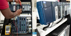
Field-Proven Installation and Hardware Protection
Physical environment factors often dictate communication reliability in heavy industries. High-noise areas like motor control centers require high-quality shielded Ethernet cabling. Always bond the cable shield at a single point to prevent ground loops. Moreover, the CI867A lacks integrated surge suppression. Installing dedicated DIN-rail surge protectors is a cost-effective way to prevent card failure during electrical storms. These small hardware investments significantly extend the lifespan of your automation assets.
Powergear X Automation: The Expert Perspective
In our experience at Powergear X Automation, the CI867A remains a workhorse for industrial integration. While newer protocols like OPC UA offer enhanced security, Modbus TCP stays relevant due to its simplicity. Success with this module requires a disciplined engineering approach rather than a “plug-and-play” mindset. Focus on robust network design and conservative polling strategies to ensure long-term uptime. If you are planning a migration, account for re-mapping time as legacy logic rarely transfers directly.
Technical Implementation Checklist
- ✅ Verify device IP addresses and subnet masks.
- ✅ Match Modbus function codes to device capabilities.
- ✅ Implement shielded CAT6 cabling for noisy environments.
- ✅ Configure heartbeat logic to detect communication loss.
- ✅ Use external surge protection for outdoor installations.
- ✅ Start with a small register block during testing.
Common Application Scenarios
- Power Management: Integrating smart meters and protection relays into the DCS.
- Skid Integration: Connecting third-party compressor or water treatment packages.
- Drive Control: Monitoring variable speed drives for energy efficiency diagnostics.
Frequently Asked Questions (FAQ)
Q1: How do I handle data timeouts and intermittent connection drops?
Timeouts usually stem from network congestion or slow slave response times. First, increase the “Reply Timeout” setting in Control Builder. If the issue persists, check for electromagnetic interference (EMI) near the communication cables.
Q2: Can I use the CI867A for high-speed motion control?
Modbus TCP over the CI867A is generally unsuitable for sub-50ms motion requirements. The overhead of the Ethernet stack and the AC 800M task cycle introduces jitter. Use specialized protocols like PROFINET or EtherCAT for high-speed applications.
Q3: What should I check if data values appear swapped or incorrect?
This is typically a “Byte Swap” or “Word Swap” issue. Check the “Endianness” settings in the CI867A hardware configuration. Adjusting the “Data Format” parameter usually resolves mapping discrepancies without changing the PLC code.