Understanding CI871K01 PROFINET IO Support for AC 800M DCS
Evaluating ABB CI871K01 PROFINET Version Support and System Impact
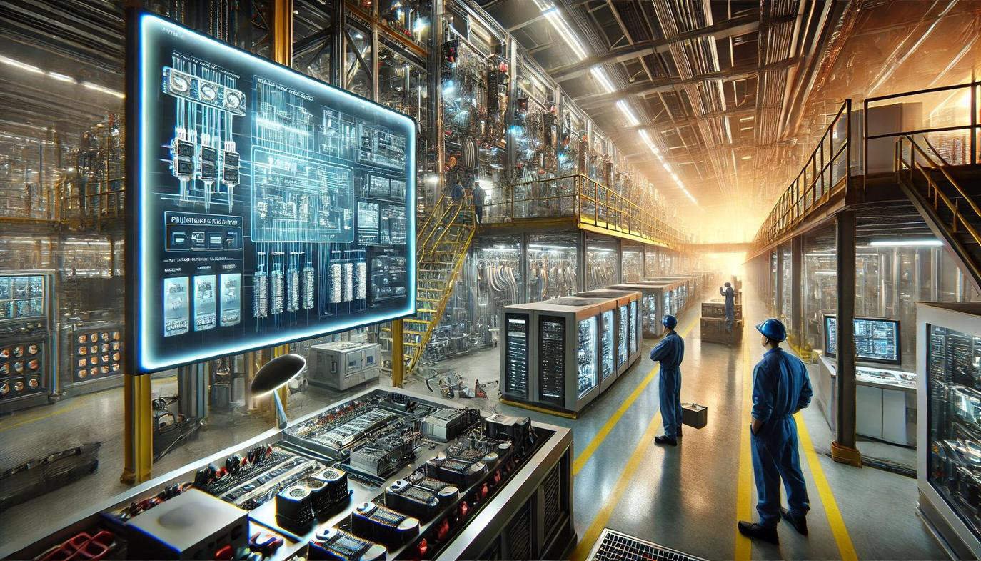
Defining the Role of CI871K01 in Modern DCS
The ABB CI871K01 (3BSE056767R1) serves as a dedicated PROFINET IO interface for the AC 800M controller family. It enables seamless communication between the DCS and decentralized field devices like drives and remote I/O. In industrial automation, this module bridges the gap between high-level control and Ethernet-based field networks. Many facilities use the CI871K01 when transitioning from traditional PROFIBUS to modern industrial Ethernet architectures. Consequently, it remains a staple in chemical processing, power generation, and large-scale manufacturing sectors.

Technical Realities of PROFINET V2.2 Specification
The CI871K01 strictly adheres to the PROFINET V2.2 specification rather than the newer V2.3 version. This distinction significantly influences system design and device selection. V2.2 primarily supports Real-Time (RT) Class 1 communication, which provides deterministic performance for most process tasks. However, it does not support Isochronous Real-Time (IRT) functions required for high-speed motion control. At Powergear X Automation, we suggest verifying your cycle time requirements before deployment. Standard RT communication typically offers stable 4ms to 10ms update rates.
Optimizing Ethernet Performance for Factory Automation
This module utilizes 10/100 Mbps Fast Ethernet to manage hundreds of cyclic I/O signals efficiently. High bandwidth ensures that the network remains stable even in complex distributed I/O topologies. Moreover, the CI871K01 maintains deterministic communication to prevent bus saturation in busy production environments. In typical packaging or refinery setups, one module easily handles dozens of PROFINET devices. Therefore, engineers can expand their field networks without compromising the integrity of the control system.
Streamlining Integration with Control Builder M
The CI871K01 integrates directly with the AC 800M platform via the Control Builder M engineering tool. This deep integration allows for automatic device parameterization using standard GSDML files. Furthermore, it centralizes hardware diagnostics within the System 800xA environment for easier troubleshooting. This approach reduces manual configuration errors and shortens commissioning timelines significantly. As a result, maintenance teams can identify field faults quickly without needing third-party diagnostic software.
Crucial Field Insights from Powergear X Automation
Our team at Powergear X Automation often observes GSDML version conflicts during site upgrades. Since the CI871K01 supports V2.2, newer devices may require backward-compatible configuration files. In addition, physical installation quality determines long-term reliability in high-vibration areas like turbine halls. Always ensure the module locks securely onto the TP867 baseplate to prevent intermittent communication alarms. We recommend using managed industrial switches and VLAN segmentation to protect the PROFINET traffic from broadcast storms.
Hardware Maintenance and Reliability Tips
- ✅ Confirm device GSDML compatibility with PROFINET V2.2 standards.
- ✅ Utilize managed switches to monitor network health effectively.
- ✅ Inspect CEX-bus connectors during every scheduled plant shutdown.
- ✅ Apply VLAN tagging to isolate control traffic from office data.
- ✅ Secure all module locking mechanisms in high-vibration environments.
- ✅ Verify IP address assignments to avoid network identity conflicts.
Industrial Solution Scenarios
- Hybrid Migrations: Integrating PROFINET remote I/O into existing PROFIBUS-heavy AC 800M systems.
- Drive Integration: Controlling multiple frequency converters in a water treatment facility.
- Legacy Support: Replacing failed units in 800xA systems commissioned between 2008 and 2016.
Strategic Procurement FAQ
Q1: Should I choose the CI871K01 or the newer CI871A for new projects?
For new installations, we recommend the CI871A or CI871AK01. These newer versions support PROFINET V2.3 and offer better compatibility with modern intelligent devices. The CI871K01 is best suited as a direct spare part for existing legacy systems.
Q2: Can this module support redundant PROFINET configurations?
The CI871K01 lacks native support for System Redundancy (SR) or Media Redundancy Protocol (MRP) at the module level. You must implement network resilience at the switch level. For high-availability requirements, consult the latest ABB hardware compatibility lists for redundant interface options.
Q3: What happens if I use a V2.3 GSDML file with this module?
Using an incompatible GSDML file often leads to configuration errors in Control Builder M. The software may fail to recognize specific device parameters or diagnostic blocks. Always request the V2.2 compatible GSDML version from your hardware vendor to ensure full functionality.