Over 50,000 hot-selling automation module components.
Allen-Bradley PowerFlex 40P Drive - Industrial Control

PowerFlex 40P: Essential Motor Control for Automation

Optimizing Motor Control: Why the Allen-Bradley PowerFlex 40P is Key for Industrial Automation

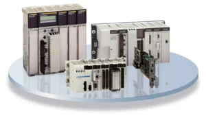
The Allen-Bradley PowerFlex 40P series is a highly reliable and efficient motor control solution. It delivers exceptional performance across many industrial applications. From basic localized systems to complex, medium-scale operations, this drive ensures consistent output. It offers flexible power options, advanced I/O, and intelligent communication capabilities. Therefore, the PowerFlex 40P provides a strategic balance of power, versatility, and affordability. Plant managers and OEMs value its compact, rugged design for managing pumps, conveyors, and general machinery. This drive truly simplifies factory automation.

Allen-Bradley PowerFlex 40P Drive - Industrial Control

Flexible Power for Diverse Industrial Applications

The PowerFlex 40P supports a wide array of voltage classes and horsepower ratings. This broad compatibility helps facilities streamline their drive inventory. As a result, standardizing control systems becomes much simpler.

Low Voltage (200–240V AC): These drives range from 0.4 to 7.5 kW (0.5 to 10 HP). They handle 2.3 to 33 Amps. These units are perfect for small machines and localized motor control.

Mid-Range Voltage (380–480V AC): Power options cover 0.4 to 11 kW (0.5 to 15 HP). They draw 1.4 to 24 Amps. This makes them ideal for mid-range operational needs.

High Voltage (500–600V AC): These robust models offer 0.75 to 11 kW (1 to 15 HP). They manage 1.7 to 19 Amps. Moreover, they suit high-demand equipment like pumps and compressors.

Author’s Comment (Powergear X Automation): In an era where the cost of capital equipment is rising, an engineer must select a drive that matches the load exactly. This series allows for precision selection, avoiding the common mistake of over-specifying power and increasing project costs unnecessarily. This design philosophy aligns perfectly with lean industrial automation practices.

Advanced Input/Output Enhances PLC Integration

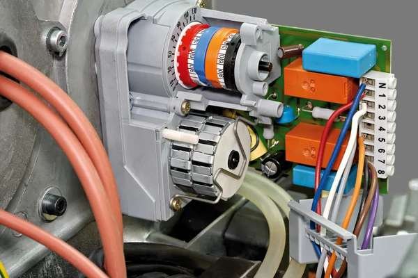
The PowerFlex 40P supports extensive I/O configurations. This reduces the need for external relays and complex panel wiring significantly. Therefore, system setup time is greatly reduced.

Digital Inputs: Two semi-programmable inputs simplify basic start/stop control. In addition, five fully programmable digital inputs enable deep customization for specific application logic.

Output Flexibility: Two opto outputs and a programmable Form C relay output provide critical real-time motor feedback and status.

Analog Signals: Analog input/output options (0–10V or 0–20mA) are selectable via a DIP switch. This ensures accurate control signals for modern DCS and PLC systems.

These streamlined I/O capabilities simplify the process of integration. They also offer users greater flexibility when tailoring drive behavior for unique control environments.

Seamless Industrial Communication for Smart Factories

The PowerFlex 40P series supports modern industrial networks natively. This often eliminates the need for expensive, extra communication hardware.

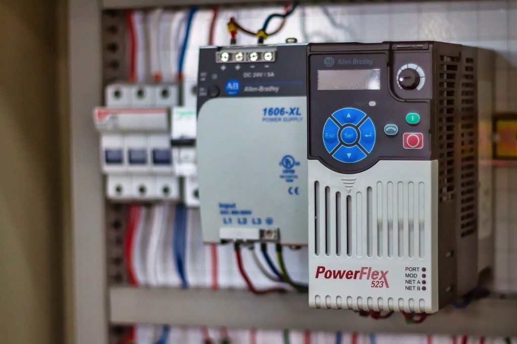
Network Support: Optional communication cards provide native support for major protocols. This includes DeviceNet, EtherNet/IP, ControlNet, PROFIBUS DP, and LonWorks.

Remote Access: Wireless Bluetooth access is available through the DSI Wireless Interface Module (WIM). This allows for easy remote monitoring and adjustment.

As a result, seamless connectivity to PLCs and HMIs reduces engineering overhead and system downtime. This feature promotes faster commissioning and diagnostics across the factory automation layer. A 2024 IEEE report highlighted that standardized fieldbus communication shortens industrial project timelines by up to 15%.

Energy Management and Precision Feedback Control

Engineers designed the PowerFlex 40P to manage dynamic loads while improving energy efficiency. It ensures consistent motor performance at all times.

Encoder Feedback: The drive auto-detects encoder feedback with 5V, 12V, or 24V DC line driver signals. This enables highly accurate speed and position control.

Smooth Operation: Moreover, PWM frequency can reach 250 kHz. This ensures very smooth and acoustically quiet operation.

Power Reliability: Ride-through functionality uses half-DC bus operation. This is critical for keeping motors running during brief power disturbances.

Energy Sharing: DC bus sharing and pre-charge control improve energy utilization. This is particularly effective across multiple drives in shared bus systems.

These energy-conscious features are key for facilities focused on achieving sustainability goals.

Built for Durability in Harsh Industrial Environments

The PowerFlex 40P series features an engineered design for durability and operational flexibility. It performs reliably in challenging field conditions.

Braking Capacity: Integrated brake resistors support rapid load deceleration. This is essential for safe operation in hoisting and high-speed conveyor applications.

Thermal Resilience: Compact frames, such as the 22D-B3P0N104, operate without extra cooling up to 50°C ambient temperatures.

Mounting Versatility: It offers flexible mounting options, including DIN rail. Enclosure ratings range from NEMA 1/IP30 to NEMA 4/IP66.

For heat-sensitive or space-constrained setups, the PowerFlex 40P offers a high-performance drive in an efficient package. This minimizes the footprint required in crowded control panels.

Versatile Motor Control for Complex Motion Profiles

The PowerFlex 40P supports both open-loop and closed-loop control methods. This gives users flexibility for various motion control requirements.

Precision Control: Closed-loop control with encoder feedback allows for high-precision speed regulation.

Motion Sequencing: Local Position Control (StepLogic) supports basic motion profiles. The drive can store up to eight steps internally.

Smooth Transitions: Zero-cross performance optimization ensures smooth motion transitions in bipolar mode.

Reference Inputs: Multiple speed references can come from analog signals or network commands. This is invaluable for coordinated drive groups in complex control systems.

These built-in features allow the drive to handle everything from basic V/Hz control to more complicated positioning tasks without expensive, external components.

Featured Applications: Real-World Solution Scenarios

The PowerFlex 40P is suitable for numerous applications across industrial automation. Here are two prime examples:

Case 1: HVAC System Optimization (Allen-Bradley 22D-B012N104)

This model operates on 208–240V AC 3-phase power. It provides 3 HP (2.2 kW) and 12 Amps of output current.

Key Features: It includes robust PID control with auto-tuning, transient protection, and integrated dynamic braking. Setup for general-purpose use is simplified.

Best Use: This unit is ideal for cost-effective motor control in small-scale applications. Think of it in HVAC systems, light conveyors, and pump stations. Its reliability and energy efficiency are critical for these uses.

Case 2: High-Demand Material Handling (Allen-Bradley 22D-B033F104)

This model runs on 240V AC 3-phase power. It delivers 10 HP (7.5 kW) and 33 Amps of output.

Key Features: It features RS485 communication, StepLogic for sequencing, and enhanced diagnostics via a 4-digit display and 10 LED indicators. Moreover, it supports Zero Stacking and DIN rail mounting.

Best Use: This is perfect for high-inertia loads and medium-to-high-demand industrial applications, such as mixers and bulk material handling. Its enhanced diagnostics ensure maximum uptime in critical processes.

Final Thoughts: The Strategic Choice for Drive Optimization

The Allen-Bradley PowerFlex 40P series is a highly strategic investment for industrial teams. It allows them to optimize motor control performance without overspending. Its robust feature set, flexible power ranges, and compact form factor meet critical requirements for value and reliability. The 40P delivers dependable operation and built-in intelligence, satisfying the high demands of both maintenance professionals and design engineers.

If you are looking for in-depth technical guides, training, or tailored system integration for your PowerFlex drives, we invite you to explore the expertise offered by Powergear X Automation.

Click here to find your next automation solution: https://www.powergearx.com/

Frequently Asked Questions (FAQ)

Q1: What is the main operational advantage of using the PowerFlex 40P over a standard V/Hz drive in a pumping application?

A: The primary advantage lies in the closed-loop control capability, particularly its PID function and encoder feedback support. A standard V/Hz drive simply controls voltage and frequency. However, the 40P can precisely adjust its output based on real-time process feedback (like pressure or flow). This provides stable process control and ensures the pump runs at the optimal speed for energy savings, which a basic drive cannot achieve.

Q2: My facility uses an older DeviceNet network. How easily can the PowerFlex 40P integrate without major upgrades?

A: Integration is straightforward. Unlike some modern drives that only offer native EtherNet/IP, the PowerFlex 40P explicitly supports optional communication cards for older fieldbuses, including DeviceNet and ControlNet. You simply install the appropriate card, and the drive becomes a native node on the existing network. This is a massive benefit for brownfield upgrades, preventing the need for costly and disruptive network overhauls.

Q3: I am an OEM building small, heat-sensitive machines. What is your experience with the drive’s thermal performance?

A: Based on our experience, the PowerFlex 40P’s ability to run up to 50°C ambient without derating (for the compact frames) is a significant design strength. This high thermal tolerance, coupled with Zero Stacking capability, means you can place the drives right next to each other in a small, sealed panel without the usual concern of a heat-related fault trip. This translates directly to a smaller overall machine footprint and reduced panel cooling costs.

5-Step Servo Drive Troubleshooting Guide

Servo Drive Repair vs. Replacement in Industrial Automation

Overview

Servo drives are the unsung heroes of precision manufacturing, providing the speed and accuracy necessary for robotics, CNC machinery, and high-speed packaging lines.When a drive malfunctions, production grinds to a halt quickly. Whether your facility relies on a Mitsubishi MR-J2S, Yaskawa SGDH, or FANUC A06B series drive, fast and effective troubleshooting is crucial. A systematic approach determines the difference between a fleeting inconvenience and a costly, extended shutdown. This expert guide walks you through a structured, five-step diagnostic process. We highlight common brand-specific failure signatures. Finally, we provide clear criteria for deciding whether to repair, replace, or escalate the issue within your factory automation system.

Step 1: Systematically Identify Failure Symptoms

Before reaching for a multimeter or a manual, you must gather detailed, observable symptoms. Simply noting “drive fault” is insufficient for accurate diagnostics. Specificity saves time.

Observable Indicators:

A specific alarm or fault code appears on the drive’s display.

The motor is completely unresponsive or exhibits erratic, jittering movement.

Motion unexpectedly stops mid-cycle, disrupting the PLC sequence.

A distinct burnt odor is present, or the drive housing feels excessively hot.

The drive shows no display and has no power indicator lights.

Pro Tip from the Field: Document the exact drive model number and the displayed alarm code immediately. Moreover, record the system’s behavior just before the failure. This information is vital for accurately isolating the root cause and defining the next course of action.

Step 2: Eliminate External Factors First (Power and Wiring)

In industrial automation, internal drive failures account for fewer issues than external problems. Before investigating complex fault codes, eliminate the simplest, most common external causes first.

Fundamental Electrical Checks:

Verify Input Voltage: Use a true RMS multimeter to confirm the drive receives the correct input voltage at the terminals.

Inspect Connections: Check all cables and terminals for loose connections, corrosion, or signs of arcing and heat damage.

Check for Shorts/Ground Faults: A short circuit in the motor winding or cabling often triggers immediate drive overcurrent alarms.

Powergear X Automation Insight: We estimate that over 40% of all reported “drive faults” are resolved by simply correcting power or wiring issues. For instance, on a Yaskawa SGDH drive, an A.C. alarm frequently points to a shorted output or incorrect motor wiring. Therefore, always confirm good grounding, especially on older legacy systems like the Mitsubishi MR-J2S, after any maintenance.

5-Step Servo Drive Troubleshooting Guide

Step 3: Interpret Drive Alarm Codes and Fault History

Servo drives incorporate sophisticated self-diagnostic capabilities. The alarm or fault code displayed on the panel is your most important clue. Different brands use distinct codes for similar failures.

Key Fault Codes by Brand:

Mitsubishi MR-J2S:

  • AL.37: Indicates Overcurrent during deceleration—often a mechanical issue or tuning problem.
  • AL.33: Points to an Encoder error—a feedback problem.

No Display: Often suggests a blown fuse or power board failure.

Yaskawa SGDH:

  • A.C.: Output short circuit—check motor/cable integrity.
  • A.E.: Overvoltage—frequently caused by poor regeneration handling.

Solid Red LED: Indicates a severe internal hardware failure.

FANUC A06B:

  • AL-1: Overcurrent—a common indication of a shorted load or motor.
  • AL-3: Regenerative error—the drive cannot dissipate energy effectively.
  • No LED: Suggests an issue with the control or power board.

Expert Tip: Many modern drives and even some legacy control systems store a fault history log. Reviewing this log helps identify patterns. In addition, recurring errors suggest environmental factors like heat, vibration, or unstable input power.

Step 4: Isolate the Problem to the Motor or the Drive

The servo drive and motor operate as a synchronized, closed-loop system. A fault originating in the motor (e.g., a shorted coil or a damaged encoder) will cause the drive to trip, masking the true source.

Motor Testing Methods:

  • Known-Good Swap: The quickest diagnostic method is temporarily swapping the suspect motor with a functional, known-good spare unit.
  • Electrical Verification: Perform a Megger test to check for shorts to ground and use a multimeter to confirm equal resistance across all motor phases.

Brand-Specific Motor Failure Notes:

  • MR-J2S: Encoder feedback problems are prevalent. Always check the integrity of the encoder cable and connector pins.
  • SGDH: Persistent A.E. or A.C. alarms often require checking for open or shorted motor windings.
  • A06B: Motors with shorts to the ground are a leading cause of damage to the power output section of the drive.

Solution Scenario: If on-site motor testing is impractical, specialized facilities offer bench testing and joint drive-motor evaluations to diagnose system interaction issues accurately before further equipment is damaged.

Step 5: Make the Informed Decision: Repair, Replace, or Retest

Downtime is costly. Your final decision—repair or replace—must balance cost-effectiveness against required recovery speed. Statista data shows that the cost of unplanned downtime in manufacturing can exceed $10,000 per hour.

ActionJustification
Repair the DriveThe failure is clearly internal (e.g., blown component). The model is obsolete or legacy (like MR-J2S) and expensive to replace. A cost-effective fix is needed, and you can tolerate a few days of turnaround time. You must retain the original application settings or custom wiring.
Replace the DriveThe same fault has recurred multiple times. There is visible, catastrophic damage (burned components, cracked boards). Immediate recovery is mandatory to prevent production line delays. You are actively upgrading the control systems to newer, supported models.
Retest or EscalateThe fault is intermittent or only happens under high load. You have replaced the drive, but the problem persists. You strongly suspect external factors like EMI or grounding issues.

Powergear X Automation offers trusted, warranty-backed repair services for legacy and current industrial automation components, including the MR-J2S, SGDH, and A06B series.

Final Thoughts: Minimizing Downtime in Motion Control

Troubleshooting a servo drive failure is manageable when you follow a structured, step-by-step methodology. By systematically checking power, wiring, fault codes, and the motor condition, maintenance teams can quickly isolate the true issue. This allows for a pragmatic decision regarding repair or replacement, minimizing the overall impact on production.

Powergear X Automation helps manufacturers maintain continuous operation by providing essential services:

Thousands of in-stock servo drives for immediate replacement.

Trusted, expert repair services for obsolete and current models.

Fast turnaround and same-day shipping on critical spares.

Don’t let a drive failure dictate your production schedule.

Need expert support, quick diagnostics, or a rapid replacement for your industrial automation components? Contact our certified team today. Click the link to explore our solutions: Powergear X Automation

Frequently Asked Questions (FAQ)

Q1: What is the significance of the “No Display” fault on a Mitsubishi MR-J2S drive, and what should I check first?

A: A “No Display” on the MR-J2S typically signifies that the low-voltage control power supply on the drive’s power board has failed. Before concluding the drive needs repair, always check the incoming control voltage fuse. If the fuse is intact, the failure is usually internal (e.g., a power supply circuit failure), requiring the unit to be sent to a dedicated repair center.

Q2: My Yaskawa SGDH drive trips on an “A.E.” (Overvoltage) alarm only when the machine decelerates quickly. Why is this happening?

A: This is a classic symptom of a failure in the regenerative circuit, which handles the energy fed back from the motor during deceleration. The drive is unable to dissipate this energy, causing the DC bus voltage to spike. The issue could be a faulty internal braking transistor, a failed external braking resistor unit (if used), or incorrect wiring to the external resistor. Check the resistor’s continuity and connections, as this is a more common point of failure than the drive’s internal components.

Q3: We have recurring encoder errors (AL.33 on MR-J2S) after a major machine vibration event. Can I fix this without replacing the drive or motor?

A: Recurring encoder errors, especially after a physical shock, suggest mechanical damage or a connection problem, not necessarily a motor coil failure. First, meticulously check the encoder cable and its connector at both the motor and the drive end for any bent pins or abrasions in the shielding. If the error persists, the encoder head or disk inside the motor is likely misaligned or damaged. Replacing the motor’s encoder unit or the entire motor is usually the required course of action, as internal encoder repair on-site is difficult.

Schneider Electric Quantum

Schneider Electric Quantum I/O and Motion Modules Guide

Welcome to the cutting-edge world of industrial automation

Today, we explore key components of the robust Schneider Electric Quantum PLC platform. This powerful system drives efficiency in countless factory automation settings. We will examine specific I/O and motion modules. Understanding these modules is crucial for reliable control systems design.

Schneider Electric Quantum

Understanding Digital Input Modules: 140DAI34000 and 140DAI35300

Digital input (DI) modules are the eyes of your PLC system. They monitor ON/OFF status from field devices. The Schneider Electric Quantum line features two notable DI modules.

140DAI34000: The Versatile AC Input Solution

The 140DAI34000 is a 24V AC input module. It handles signals from AC-powered sensors or switches. This module offers 16 discrete input points. Its isolation protects the internal electronics effectively. Therefore, it is ideal for noisy industrial environments. Moreover, its design ensures high signal integrity.

✅ Function: Digital AC Input
⚙️ Voltage: 24V AC Nominal
🔧 Points: 16 Discrete Inputs

140DAI35300: High-Density DC Input Power

The 140DAI35300 increases input density significantly. This module provides 32 points of 24V DC input. Using DC power is standard for many modern sensors. As a result, this module saves valuable rack space. Engineers often choose it for large-scale applications. Its high density reduces system footprint and cost.

✅ Function: Digital DC Input
⚙️ Voltage: 24V DC Nominal
🔧 Points: 32 Discrete Inputs

Schneider Electric Quantum

Digital Output Modules: Driving Industrial Actuators with Precision

Digital output (DO) modules are the hands of the DCS or PLC. They send ON/OFF commands to actuators. These actuators include relays, solenoids, and motor starters.

140DDO15310: High-Speed TTL Output for Critical Control

The 140DDO15310 features TTL (Transistor-Transistor Logic) output. TTL signaling is very fast and low voltage (5V DC). This makes it perfect for connecting to other logic circuits. Consequently, engineers use it in high-speed communication applications. It is less common for direct solenoid control.

✅ Function: Digital TTL Output
⚙️ Signal Type: TTL (5V DC)
🔧 Application: High-speed signaling, inter-logic device communication

140DDO88500: Robust High-Power DC Switching

The 140DDO88500 provides powerful DC output switching. This module typically handles 24V DC field loads directly. It offers 12 isolated output points. High current capacity is a key feature here. Therefore, it can drive larger industrial devices. This module is a workhorse in general industrial automation.

✅ Function: Digital DC Output (High Power)
⚙️ Voltage: 24V DC Nominal
🔧 Points: 12 Discrete Outputs

Understanding the Principles and Application Scenarios

The fundamental principle for all these I/O modules is electrical isolation. Isolation protects the sensitive PLC backplane from field noise. High-speed counting or simple state monitoring dictates the module choice.

Application Scenarios:
Process Plants (Oil & Gas): DI/DO modules monitor valve positions and pump status.
Manufacturing Lines: They control conveyor belts and robotic grippers.
Building Automation: They manage lighting and HVAC equipment.

Schneider Electric Quantum

The Specialized Motion Control: 140MSB10100

Motion control is a specialized subset of industrial automation. It demands very precise timing and command execution.

140MSB10100: Dedicated Servo and Stepper Control

The 140MSB10100 is a dedicated motion control module. It manages complex motion profiles for motors. This includes position, velocity, and torque control. In addition, it offloads demanding calculations from the main CPU. This improves overall system performance. A recent MarketsandMarkets report suggests motion control is a key growth area in factory automation.

✅ Function: Multi-Axis Motion Control
⚙️ Control Type: Servo and Stepper Motor
🔧 Benefit: Enhanced precision and reduced CPU load

Selecting the Right Quantum Module: Key Distinctions

Module selection depends entirely on field requirements. Distinctions exist in signal type, density, and speed.

Feature140DAI34000 (AC)140DAI35300 (DC)140DDO15310 (TTL)140DDO88500 (DC)
Signal TypeAC (24V)DC (24V)DC (5V Logic)DC (24V Power)
Point DensityLow (16)High (32)High (20+ typically)Low (12)
Speed/PowerStandardStandardHigh Speed/Low PowerStandard/High Power

The 140MSB10100 stands apart. It handles complex algorithms, unlike the simple I/O modules. Choosing between the 140DAI series means assessing field voltage. Output choice balances speed (TTL) versus power (High Current DC).

Author’s Insight: Powergear X Automation’s Perspective

As an experienced engineer, I see a clear trend. The push for smarter factories requires this module diversity. High-density I/O like the 140DAI35300 minimizes cabinet size. Dedicated motion control (140MSB10100) is non-negotiable for high-throughput machines. However, simple I/O remains the backbone. Therefore, correctly scoping your I/O is critical. Many projects fail due to inadequate field device power budgeting. Always over-spec your output current capacity slightly.

To explore more advanced automation solutions, please visit Powergear X Automation https://www.powergearx.com/. We offer expert consultation on designing robust control systems.

Application Case Study: Automated Packaging Line

A client needed a high-speed, flexible packaging solution.
Solution: We chose the 140DAI35300 for 24V DC sensor inputs (32 points). The 140DDO88500 controlled the pneumatic solenoids. Crucially, the 140MSB10100 managed the product indexing servo motor. This combination ensured both fast throughput and precise material handling. The system achieved a 15% increase in production rate.

Frequently Asked Questions (FAQ)

Q1: How do I decide between AC and DC input modules for a legacy system?
A1: Check the voltage of your existing field devices (e.g., limit switches). If they run on 120V AC, you must use an AC input module like the 140DAI34000. If you are installing new 24V sensors, always opt for DC inputs. DC is generally safer and less prone to electrical noise.

Q2: What is the main experiential challenge when commissioning the 140MSB10100?
A2: The biggest challenge is parameter tuning. A simple I/O module is plug-and-play. The 140MSB10100 requires precise configuration of motor parameters. You must accurately tune the Proportional-Integral-Derivative (PID) loop. This ensures smooth acceleration and deceleration, preventing mechanical stress and instability.

Q3: Can I mix Quantum I/O modules from different voltage ranges in the same rack?
A3: Yes, you can. The Quantum backplane manages the communication regardless of module voltage. However, never mix the field wiring voltages. For example, ensure 24V DC is only connected to your DC modules. Mixing field voltages can permanently damage the modules.

Maximizing Performance with Allen-Bradley Kinetix 300

Maximizing Performance with Allen-Bradley Kinetix 300: A Step-by-Step Setup Guide

Introduction

The Foundation: Hardware and Software Setup

Before we do anything, let’s get the basics right. A good start makes everything else easy.

Mounting and Wiring

This might sound simple, but it’s crucial. Ensure the drive is mounted in a cabinet with proper airflow. Heat is the enemy of electronics. When wiring, pay close attention to the manual. I’ve seen countless hours wasted because of a simple wiring mistake. Make sure your power, motor, and feedback cables are correctly terminated and shielded to prevent electrical noise.

Maximizing Performance with Allen-Bradley Kinetix 300

Software Installation

You’ll need the Studio 5000 Logix Designer and DriveTools SP. Make sure you have the latest versions. Compatibility issues between software and firmware are a common headache. My tip? Always check the Rockwell Automation Product Compatibility and Download Center (PCDC) before you start. It saves so much time later.

Getting Connected and Configuring the Drive

Now that the physical setup is done, let’s talk about the digital side. This is where the magic happens.

Establishing Communication

Connect your PC to the Kinetix 300 via an Ethernet cable. Open Studio 5000 and add the drive to your project’s I/O configuration. The Kinetix 300 uses EtherNet/IP, which makes this part very straightforward. Make sure your IP addresses are set up correctly. A unique IP for each device is a must.

Drive Configuration

Once connected, open DriveTools SP. Here’s where you input all your motor and application data. Don’t guess here. Use the motor’s nameplate data. The Kinetix 300 has a powerful auto-tuning feature, but it works best with accurate information. My unique insight? I’ve found that manually inputting the motor’s inertia can sometimes give you a better starting point than letting the software guess.

The Power of Tuning and Optimization

This is the most important step for maximizing performance. A poorly tuned drive can lead to shaky motion, overshoot, and instability.

The Auto-Tune Feature

The Kinetix 300’s auto-tune is an excellent starting point. It calculates the basic PID (Proportional, Integral, Derivative) values for your system. Run this feature with the motor disconnected from the load first, if possible. This gives a clean, accurate baseline.

Manual Tuning (Pro Tip)

After auto-tuning, you often need to fine-tune the system. I always start with the Proportional Gain (Kp). Increase it slowly until you see the motor start to oscillate, then back off a bit. Next, add some Integral Gain (Ki) to eliminate any steady-state error. Finally, use a small amount of Derivative Gain (Kd) to dampen any overshoot. My secret? Use the Trend tool in Studio 5000 to visualize the motion profile. It’s the best way to see what’s happening and make precise adjustments.

Conclusion: Achieving Peak Performance

By following these steps, you’ll go from a basic setup to a high-performance system. The Allen-Bradley Kinetix 300 is a robust and capable drive. The key to unlocking its full potential is a careful, systematic approach. Getting the hardware and software basics right, configuring the drive accurately, and taking the time to fine-tune your application will result in smooth, precise, and reliable motion.

Remember, a well-tuned system is a happy system. It reduces wear and tear, increases efficiency, and makes your machine more productive.

Ready to start your next project? We have the Allen-Bradley Kinetix 300 and all the necessary accessories you need.

Click here to explore our full range of Allen-Bradley Kinetix products at Powergear X Automation Limited!

Back to Top
Product has been added to your cart