Troubleshooting Emerson VE6049M01 Two Red LED Flashes Fault
Troubleshooting the Emerson VE6049M01: Understanding the “Two Red LED Flashes” Fault
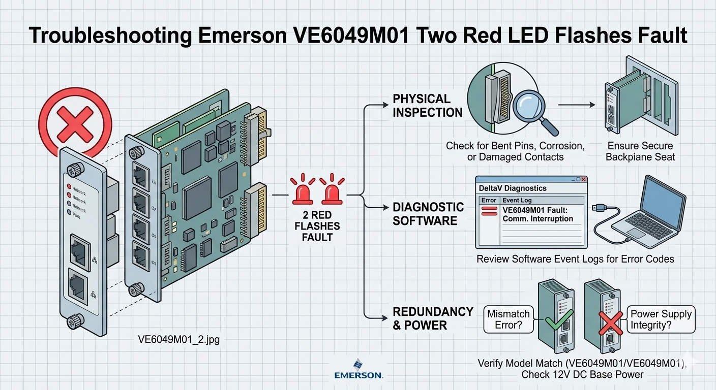
In the world of industrial automation, clear diagnostics save time and money. The Emerson VE6049M01 interface module serves as a critical link in the DeltaV DCS ecosystem. However, maintenance teams often encounter a specific fault signal: two repeating red LED flashes. This visual alarm indicates a hardware initialization failure or a self-test error. Understanding the root causes of this pattern helps engineers avoid unnecessary downtime in continuous-process environments.

Troubleshooting Emerson VE6049M01 Two Red LED Flashes Fault
The Functional Role of VE6049M01 in Factory Automation
The VE6049M01 provides essential communication between DeltaV controllers and I/O subsystems. It manages high-speed data exchange required for real-time control logic. As a result, any failure in this module can impact refinery safety or chemical batch quality. Industries such as oil & gas and power generation rely on this hardware for its high availability. The module translates complex electrical signals into actionable data for the DCS.
Technical Analysis of Initialization Faults and Power Stability
Voltage quality plays a decisive role in module startup. The VE6049M01 requires a clean 24VDC supply to initialize its internal logic successfully. Excessive ripple or transient sags during boot-up often trigger the two-flash red LED error. Standard multimeters might show a steady 24V reading. However, only an oscilloscope can reveal the high-frequency noise that disrupts sensitive electronics. Therefore, checking power quality is the first step in effective troubleshooting.
Backplane Integrity and Mechanical Communication Failures
Mechanical issues frequently mimic electronic hardware failures in industrial control systems. A two-flash red LED often signals that the module cannot communicate with the carrier backplane. Oxidation on gold edge connectors or bent pins can interrupt data packets. Moreover, constant vibration in compressor houses or offshore platforms may loosen the module seating. Engineers should inspect the physical connection before assuming the module is defective. Re-seating the module often clears the fault immediately.
Firmware Compatibility in Modern Distributed Control Systems
Compatibility issues often arise during phased plant modernization projects. Newer VE6049M01 hardware might not communicate correctly with legacy DeltaV software revisions. If the controller firmware does not recognize the module’s revision, the initialization self-test will fail. This mismatch presents as a persistent diagnostic alarm. Maintenance teams must verify the Emerson compatibility matrix before installing replacement units. Alignment between software and hardware ensures long-term system stability.
Best Practices for Installation and Maintenance
- ✅ Verify Load Voltage: Test the 24VDC supply while the system is under full load.
- ⚙️ Confirm Seating: Ensure the module clicks firmly into the carrier slot.
- 🔧 Inspect Pins: Use a magnifying tool to check for bent or oxidized backplane connectors.
- 📊 Check Software: Cross-reference firmware versions in the DeltaV explorer.
Expert Insights from Powergear X Automation Limited
At Powergear X Automation Limited, we observe that nearly 30% of “failed” modules are actually victims of poor infrastructure. Issues like grounding loops and aging power supplies create phantom faults. We recommend a “swap-test” method. Move the suspect module to a known-good carrier slot to isolate the problem. If the fault persists, only then should you proceed with procurement. For genuine Emerson components and technical consultation, visit our official site at https://www.powergearx.com/.
Application Scenario: Chemical Plant Power Disturbance
Consider a chemical plant experiencing intermittent “Two Red Flash” alarms on their VE6049M01 modules. After investigating, engineers found that large motor starts were causing momentary voltage sags. These sags didn’t trip the breakers but confused the module’s startup logic. By installing a dedicated power conditioner for the DeltaV cabinet, the plant eliminated the alarms. This solution saved thousands of dollars compared to replacing multiple interface modules.
Frequently Asked Questions (FAQ)
Q1: Does the “Two Red Flash” pattern always mean the hardware is broken?
A: Not necessarily. In our experience, this pattern frequently stems from external factors like backplane communication loss or poor power quality rather than internal circuitry failure.
Q2: Can I perform a hot-swap on the VE6049M01 while the process is running?
A: While DeltaV supports hot-swapping, you must first verify redundancy status. Pulling a module without a healthy backup can trigger a fail-safe shutdown of the entire I/O rack.
Q3: Why does the module work sometimes after a cold restart?
A: Initialization depends on timing and voltage levels. A cold restart might provide a slightly cleaner startup sequence, allowing the module to bypass a marginal self-test failure temporarily.