ABB S800 I/O Integration Guide: CI532 vs CI522A Comparison
Strategic Integration of ABB S800 I/O: Navigating the CI532 and CI522A Selection
The Vital Role of Communication Interfaces in Multi-Vendor Systems
In modern industrial automation, the ability to bridge disparate hardware ecosystems determines system flexibility. The ABB CI532 and CI522A represent two distinct paths for S800 I/O connectivity. While they look similar, their underlying protocols serve completely different architectural roles. For engineers integrating ABB I/O with third-party controllers like Siemens or Rockwell, making the wrong choice leads to costly communication bottlenecks. Consequently, understanding these functional boundaries is essential for maintaining a lean and responsive control network.
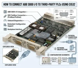
How to Connect ABB S800 I-O to Third-Party PLCs Using CI532
CI532: The Universal Bridge for Third-Party PLC Integration
The CI532 functions as a high-performance PROFIBUS DP-V0/V1 slave interface. This standardization allows the S800 I/O to appear as a native remote node to any PROFIBUS-capable PLC. In industries like chemical processing and oil and gas, mixed-vendor environments are common. Therefore, the CI532 solves the fundamental challenge of protocol compatibility. It enables stable, high-speed data exchange without requiring specialized ABB-proprietary software for the master controller. Moreover, it leverages standard GSD files for seamless configuration in environments like TIA Portal or Studio 5000.
CI522A: Specialized Connectivity for Legacy AF100 Ecosystems
Conversely, the CI522A is purpose-built for the Advant Fieldbus 100 (AF100) protocol. This is a proprietary ABB communication bus primarily found in legacy Advant and AC800M systems. While robust within its native ecosystem, it lacks direct compatibility with non-ABB PLCs. Using a CI522A in a third-party integration usually requires additional protocol gateways. As a result, this adds unnecessary latency and increases the number of potential failure points. Therefore, we recommend reserving the CI522A strictly for maintenance or expansion of existing ABB-centric architectures.
Ensuring Determinism in High-Speed Process Applications
Data exchange determinism directly impacts production quality in sectors like pharmaceutical manufacturing. The CI532 utilizes cyclic communication to ensure predictable scan times. Deterministic I/O updates prevent critical errors such as valve timing offsets or inconsistent mixing ratios. According to industry reports from organizations like PI (Profibus & Profinet International), maintaining a stable bus cycle is crucial for process variability reduction. By choosing the CI532, engineers align their I/O performance with the PLC’s logic scan for synchronized operation.
Field Maintenance and Installation Best Practices
Successful deployment of S800 I/O modules depends heavily on physical layer integrity and configuration accuracy. Technical teams should adhere to the following standards to maximize uptime:
- ✅ PROFIBUS Termination: Always enable active termination at the first and last physical nodes of the network.
- ✅ Shielding Protocols: Ground the cable shield at a single point to prevent interference from ground loops.
- ✅ GSD Versioning: Ensure the GSD file revision matches the hardware firmware to avoid configuration faults.
- ✅ Mechanical Seating: In high-vibration skids, verify that modules are fully locked into their terminal bases.
Strategic Analysis from Powergear X Automation Limited
At Powergear X Automation Limited, we advocate for “Direct-to-Protocol” strategies. While gateways can bridge CI522A to modern networks, they often obscure diagnostics. The CI532 remains the most reliable “Plan A” for legacy I/O migration or multi-vendor projects. However, as the industry shifts toward Industry 4.0, we also encourage users to evaluate PROFINET alternatives for new designs. The CI532 offers a proven, stable bridge today, but future-proofing requires a keen eye on Ethernet-based evolution.
Application Scenarios and Practical Solutions
- Retrofit Projects: Use the CI532 to keep existing S800 I/O hardware while upgrading the master PLC to a modern Siemens S7-1500.
- Offshore Skids: Implement CI532 for deterministic control of dosing pumps where timing precision is non-negotiable.
- Legacy Maintenance: Utilize the CI522A only when replacing failed units within an established ABB AF100 network.
Technical Comparison FAQ
Q: Can I convert a CI522A system to PROFIBUS without changing the I/O modules?
Yes. One of the greatest advantages of the S800 system is the modularity of the communication interface. You can replace the CI522A head station with a CI532. This change allows the existing I/O modules on the same cluster to communicate via PROFIBUS without re-wiring the field signals.
Q: Why does my PLC report a configuration mismatch even though the I/O is correct?
This is frequently caused by a GSD file mismatch. PROFIBUS masters are very strict about the identification number and module parameters. Verify that the “Module Identity” settings in your configuration tool exactly match the physical hardware revision of the CI532.
Q: What is the maximum distance for a CI532 PROFIBUS segment?
The distance depends on the baud rate. At 1.5 Mbps, the segment limit is typically 200 meters. For longer distances, such as 1000 meters, you must drop the speed to 187.5 kbps or utilize PROFIBUS repeaters to maintain signal integrity.
To source genuine ABB components or receive expert consultation on your next integration project, visit the Powergear X Automation Limited official website.